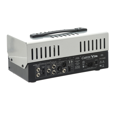
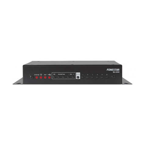
SIRIUS PRO MXC Series User manual

POWER
B
PRO
CLIP
SIGNAL
A
PRO
CLIP
SIGNAL
C
PRO
CLIP
SIGNAL
D
PRO
CLIP
SIGNAL
E
PRO
CLIP
SIGNAL
F
PRO
CLIP
SIGNAL
G
PRO
CLIP
SIGNAL
H
PRO
CLIP
SIGNAL
MIN MAX MIN MAX MIN MAX MIN MAX MIN MAX MIN MAX MIN MAX MIN MAX
8
8
8 CHA NNE L AMP LIF IER
8 Kanal Verstarker
Multi-Channel Amplifier MXC series

Advantages Introduction
EINFUHRUNG
Dieser Verstarker eignet sich hervorragend
fur die Bereiche: Professionelle Anwendung
in multifunktionellen Raumen, Studios, Sho-
wrooms, Discotheken, Nachtclubs, Karaoke
-Bars, DJ`s, etc.....
Der Verstarker besticht durch seine
sehr elegante, sowie anspruchsvolle Bauart.
exklusive und
Perfekter Schutz durch: Gleichstrom schutz,
Uerhitzungs schutz, Luftkuhlung, Soft-Start,
Over load schutz, Clip Indikator, etc.....Diese
Schutzmaβnahmen garantieren ein sicheres
und zuverlassiges Arbeiten.
Sorgfaltig ausgewahlte, technis
ermoglichen eine hohe Soundeffizienz.
che Losungen
Die Endstufe lasst sich fur verschieden
einsetzen. Ein lowcut Filter ermoglicht es die
Frequenz unter 80 Hz abzufiltern.
Einsatzzwecke des puren Klangerlebnisses
Jeweils zwei Kanale konnen zu einem Ka-
nal gebruckt werden.
Composed with our AREA SELECTORS (w-
mstances for pure sound.
Every two channels can be bridged to
Elegant professional exterior design, made
Perfect protection including: DC protect,
soft start, overload protect, and clip, etc.
These protect methods guarantee a safe
Accurate resolution ability brings you an
Signal of CHA can be selected to any channel.
This amplifier is a good choice for professional
DJ etc.
application for multifuntional chamber, studio,
showplace,disco, nightclub, Karaoka Room,
ith transformers inside),this amplifier can be
used as a Public Address System.
The amplifier is suitable for various circu-
one channel. The output power is much bi-
gger.
from exclusive mould.
high temperature protect,air-cooling system,
work status with reliable efficiency.
outstanding sound effect.
Ausgestattet mit Drehreglern,um die Lautstarke zu
regeln.
Dieser Verstarker kann fur public A-
ddress Anwendungen benutzt werden.
Das an Channel 1 anliegende Signal
kann an jedem kanal ausgegeben werden.

8
8 C HAN N E L A M P LIF I E R
Front
1.Installing Hole
2.Air cooling window
3.Protection indicator
If the amplifier overheats,the protection system
activates. In this case,you should turn off the
amplifier and allow it time to cool down.When it
has cooled down,the protection system deacti-
vates automatically and the amplifier can be t-
urned on again ready for normal operation.See
the Precautions section of this Owners Manual
for ways to prevent the amplifier overheating.
The protection system activates if a DC voltage is
detected at the amplifiers outputs. Once the DC
voltage problem is corrected, the protection system
deactivates automatically and the amplifier is ready
for normal operation.
the protection system activates for approximately
three seconds when the amplifier is turned on.
After three seconds, the protection system deac-
tivates automatically and the amplifier is ready for
normal operation.(Soft Start)
When the protection system is active, the PROT-
ECTION indicator lights up and the speakers are
automatically disconnected from the amplifiers o-
utputs.The protection system activates in the foll-
owing situations:
When the amplifier is turned on
If a DC voltage is detected at the amplifiers
If the amplifier overheats
This part is the air cooling window. Dont obstruct
it.
B
PRO
CLIP
SIGNAL
A
PRO
CLIP
SIGNAL
POWER
C
PRO
CLIP
SIGNAL
D
PRO
CLIP
SIGNAL
E
PRO
CLIP
SIGNAL
F
PRO
CLIP
SIGNAL
G
PRO
CLIP
SIGNAL
H
PRO
CLIP
SIGNAL
MIN MAX MIN MAX MIN MAX MIN MAX MIN MAX MIN MAX MIN MAX MIN MAX
12
543
78
6
2.Luftkuhlungsschachte:
Verhindern Sie bitte jegliche Verschmutzung
und Verstopfung dieser Schachte.
1.Vorgestanzte 19" Installationslocher.
Diese Locher dienen zur einfachen Transportierung
des Gerates in einem Case / Rack.
3.Protect Indicator
Wenn das Schutzsystem aktiv ist, leuchtet der Sch-
utzindikator auf, und die Lautsprecher werden aut-
omatisch ausgeschaltet.
Der Schutzindikator wird in den folgenden Situatio-
nen aktiviert:
Wenn der Verstarker eingeschaltet wird.
Der Schutzindikator leuchtet etwa drei Sekunden a-
uf, wenn der Verstarker eingeschaltet wird.
Wenn eine Gleichstromelektrische Spannung am
Verstarker wahrgenommen wird. Sobald die Gleic-
hstromelektrische Spannung korrigiert ist, deaktiv-
iert sich das Schutzsystem automatisch.
Wenn der Verstarker uberhitzt ist.
In diesem Fall mussen Sie den Verstarker fur einige
Minuten ausschalten, so dass er abkuhlen kann.

7.Power switch
5.Signal indicator
4.Clip indicator
A channels CLIP indicator lights up when its output
distortion exceeds 1%(i.e.,clipping).Output signal
clipping is typically caused by excessive input signal
levels.
A channels SIGNAL indicator lights up when its output
exceeds 2 V rms,.which is equivalent to 1/2watt into 8
ohms,or 1 watt into 4 ohms.
Use this switch to switch your power amplifier on.
8.Handles Installing
6.Attenuators
These detentedcontrols are used to attenuate the
input signal from MIN to MAX for each channel. In
Bridge mode,only the attenuator of the first channel
in the pair is active,i.e.,channel A of pair A-B,channel
C of pair C-D,channel E of pair E-F, and channel G
of pair G-H.
4.Clip Indicator
Ein clip indicator (Trimmindikator) leuchtet auf, wenn
die Ausgangsverzerrung 1% ubersteigt.
5.Signal Indicator
Ein Signalindikator leuchtet auf, wenn die Ausgan-
gsverzerrung 2V RMS ubersteigt
6.8 Regler um die Lautstarke zu regeln.
7.An/ Aus Schaller
8.Diese Locher dienen zur einfachen
Transportierung des Gerates mit
Halterungen.

BRI DGE BRI DGE
+
-
BRI DGE
+
-
P
H
U
S
ABCDEFGH
ON
OFF OFF
ON
OFF
ON
OFF
BRI DGE
ON OFF
AC INPUT
(230V/ 50 )Hz
FUSE
(230V/ 20A)
FROM CHA
HPF 80 HPF 80
FROM CHA
INPUT INPUT INPUT INPUT
SERIAL NO.:
CAUTION
RISK OF ELECTRIC SHOCK
DO ONT OPEN
XLR
1=GROUND
2=SIGNAL/+
3=SIGNAL/-
SPEAKER
1+=CHA/+
1- =CHA/-
1+=CHB/+
1- =CHB/-
+
-
+
-
BRI DGE
SPEAKER OUTPUTS
1
3
21
3
21
3
21
3
21
3
21
3
21
3
21
3
2
ON
TECHNOLOGY FROM U.S.A
MADE IN P.R. O.CH
ON
OFF OFF
ON
OFF
ON
OFF
BRI DGE
ON OFF
FROM CHA
HPF 80 HPF 80
FROM CHA
ON ON
OFF OFF
ON
OFF
ON
OFF
BRI DGE
ON OFF
FROM CHA
HPF 80 HPF 80
FROM CHA
ON ON
OFF OFF
ON
OFF
BRI DGE
ON OFF
FROM CHA
HPF 80 HPF 80
ON
+
-
+
-
SPEAKER OUTPUTS
+
-
+
-
SPEAKER OUTPUTS
+
-
+
-
SPEAKER OUTPUTS
Rear
1.Speaker outputs
1.Speaker outputs
3.Low Cut (HPF-Schalter)
5.From switch
These 8-way binding posts are used to connect
speakers.
The following illustrations show how speakers
should be connected for normal and Bridge mode
operation.
+
-
+
-
BRIDGE
SPEAKER OUTPUTS
+
-
+
-
+
-
BRIDGE
SPEAKER OUTPUTS
+
-
BRIDGE
ON OFF
Normal mode
Dieser Schalter dient zum Abschneiden der Niederen
Frequenzen. Der Schalter kann die Frequenz unter
80Hz filtern.
+
-
+
-
Speaker
min.4W
Speaker
min.4W
Bridge mode
BRIDGE
ON OFF
+
-
Speaker
min.8W
1
3
67
2 54
2.XLR Input fur jeden kanal
4.
Der BRIDGE Schalter dient dazu um zwei Kana-
le zu brucken, sie erhalten dadurch eine hohere
Leistung.Gebruckt: 400W * 8Ohm
Stecker zur Verbindung des Gerates mit der Steckdose.
6.AC Cord
die Quelle uber 230Volt verfugt.
Bitte vergewissern Sie sich vor dem Einstecken, dass
2.Input XLR
3.HPF switches
4.BRIDGE switches
5.FROM switches
6.Main Power
7.Power fuse
Die Sicherung dient zum Schutz des Gerates vor
unterschiedlichen AC Storungen. Wenn das Great
in Betrieb ist, jedoch kein Lampchen leuchtet, ub-
erprufen Sie bitte die Sicherung. Wechseln Sie di-
ese gegebenenfallsaus und ersetzen Sie diese d-
urch eine gleichstarke Sicherung.
7.Fuse

MXC 8 GENERAL SPECIFICATIONS
Power Output Level RMS@8ohm stereo
1kHz,T HD+D=0.1%
RMS@4ohm stereo
RMS@8ohm bri dge
Phase respones
(1W,2 0Hz-20kHz@8ohm)
Total Harmonic Distortion 20Hz~20kHz, Half power
Frequency Response
1W/8ohm
Slew Rate
15V/μs
Intermodulation Distoration 60Hz:7kHz, 4:1, Half Power
Channel Separation
Half Power,RL=8ohm
1kHz Vol.max., input 600ohm shunt
SN Ratio
>90dB
Damping Factor
8ohm, 1f=1kHz
Sensiti vity(Vol.m ax.)
Rated Power into 8ohm
Input impedance
balanced/u nbalanced
Contro ls
Front Panel
Rear Panel
Input Connectors
Output Connectors
LED Indicators
per channel
per channel
per channel
Prote ction Circ uit
Class AB
Power Supply
US&CANADA
8*140W
8*210W
4*400W
`+/- 10°
<0.1%
20Hz-2 0kHz +/- 1dB
<0.03%
>60dB
>60dB
250
110V, 60Hz
short circ uit prote ct, over load pro te ct, DC pro te ct, soft sta rt,
hign te mpera ture pro tect limite r
prote ct, clip,s ignal
binding posts
female XLR
Power Switc h (on/o ff), Volume/CH
20Kohm / balanced, 10Kohm / unbalanced
1V
EUROPE
OTHER
230V, 50Hz
220V, 50Hz
Cooling
two indivldual cooling fan controlled by temperature
Dimensions
mm
Weight kg 25
482*1 34*4 83
MXC 8 TECHNISCHE DATEN
Ausgange
..
..
Eingange
..
Gerauschspannungsabstand
..
Dam[fungsfa kto r
Ausgangsleistung
RMS@8ohm stereo
1kHz,T HD+D=0.1%
RMS@4ohm stereo
RMS@8ohm bri dge
Phasenfrequenzgang
(1W,2 0Hz-20kHz@8ohm)
Klirrfaktor
20Hz~20kHz, Half power
Frequenzgang
1W/8ohm
Anstiegsrate
15V/μs
Intermodulation Verzerrung
60Hz:7kHz, 4:1, Half Power
Kanaltrennung
Half Power,RL=8ohm
1kHz Vol.max., input 600ohm shunt
>90dB
8ohm, 1f=1kHz
Empfi ndlichkeit(V ol.m ax.)
Rated Power into 8ohm
Eingangsimpedanz balanced/u nbalanced
Kontro llen
Front Panel
Rear Panel
LED Indikatoren
pro kanal
pro kanal
pro kanal
Schutz schalter
Klasse AB
Stro mvers org ung
US&CANADA
EUROPE
ANDERE
230V, 50Hz
220V, 50Hz
Kühlung
zwei individuelle durch Temperatur kontrollierte Ventilatoren
Maβe mm
Gewicht kg 25
8*140W
8*210W
4*400W
`+/- 10°
<0.1%
20Hz-2 0kHz +/- 1dB
<0.03%
>60dB
>60dB
250
482*1 34*4 83
110V, 60Hz
Schutz , clip Signal,
binding posts
female XLR
bridge switc h,HPF switch,f= 80Hz -12dB/o ct,F rom CHA switch
Netzschalter (a n/a us), Volume/C H
20Kohm / balanced, 10Kohm / unbalanced
1V
..
Kurzs chluβsich erun g, Uberl astsc hutz, DC Sch utz, Softsta rt ,
Temperaturs chutzli miter
bridge switc h,HPF switch,f= 80Hz -12dB/o ct,F rom CHA switc h

Importeur:
B&K Braun GmbH
Industriestra e 1
76307 karlsbad
Germany
www.sirus-pro.de
This manual suits for next models
1
