Sirman TC 22 Instruction manual

1
English
TC_22-32_003
Ed. 12.2018
MEAT GRINDER
INSTRUCTION MANUAL FOR USE AND MAINTENANCE
TC 22
TC 32

3
English
CONTENTS
1. Delivery and guarantee 5
1.1 Introduction
1.2 Storage and use of this manual
1.3 Warranty
1.4 Machine description
1.5 Intended use
1.6 Prohibited uses
1.7 Identification data
1.8 Guards and safety devices
1.9 Work position
2. Specifications 9
2.1 Main parts
2.2 Specifications
2.3 Size and weight of the machine.
2.4 Wiring diagrams
3. Controls and Indicators 15
3.1 List of controls and indicators
4. Testing, transport, delivery and installation 15
4.1 Testing
4.2 Shipping and handling of machine
4.3 Installation
4.3.1 Disposal of packaging
4.3.2 Handling the machine
4.4 Connection to the electric mains
4.4.1 Three-phase machine
4.4.2 Single-phase machine
5. Starting and stopping 16
5.1 Check for correct electrical connection
5.2 Check for the presence and effectiveness of guards and safeties
5.3 Check for efficiency of the stop button
5.4 Starting the machine
5.5 Stopping the machine
6. Using the machine 17
6.1 Requirements
6.2 Preparation of the output feed
6.3 Using the meat grinder
6.4 - Dismantling and cleaning the mouth after use
6.5 - Assembling the mouth after cleaning
6.6 - Manual hamburger forming accessory
6.6.1 - Assembling the hamburger forming accessory
6.6.2 - Using the hamburger forming accessory
6.6.3 Detaching the hamburger forming accessory from the meat grinder

4
7. Maintenance 21
7.1 Lubrication
7.2 Cleaning the machine
7.3 WEEE Waste Electrical and Electronic Equipment
8. Troubleshooting 22
8.1 Faults, causes and remedies.

5
English
1 - Delivery and Warranty
1.1 - Introduction
WARNING! The symbols used in this manual are intended to draw thereader'sattention
to issues and operations hazardous to the personal safety of the opera-tors, or where there
is risk of damage to the machine itself.
Do not operate the machine if you are not sure that you correctly understand what has been
shown in these notes.
WARNING! Some of the illustrations in this manual, for reasons of clarity, showthe
machine or parts of it with the panels or guard removed.
Do not use the machine in such conditions,only use if provided with every protec-tion
properly fitted and working perfectly.
The manufacturer prohibits the reproduction, even partial, of this manual, and its contents
cannot be used for purposes not permitted by thesame. Violatorswill be prosecuted
according to law.
1.2 - Conservation and use of this manual
The purpose of this manual is to inform users about the machine using text and figures to
clarify the requirements and criteria essential for the transport, handling, use and
maintenance of the machine. Thus, before using the machine read this manual carefully.
Keep it safe near the machine, in a place easily and quickly ac-cessible for future reference.
If the manual is lost or damaged, obtain a copy from your dealer or directly from the
manufacturer. In case of selling the machine, inform the manufacturer of the details and
contact information of the new owner.
The manual reflects the state of the art at the moment of its sale of the machine and cannot
be considered unsuitable if, subsequent to new experiments, it were to be further upgraded.
In this regard, the manufacturer reserves the right to update products and manuals without
having to upgrade the product and previous manual, except in exceptional cases. If in doubt
consult your nearest service centre or the manufacturer directly. The manufacturer is striving
for the continuous improvement of its product.
For this reason, the manufacturer is pleased to receive anysuggestion or proposal intended
to improve the machine and/ or manual. The machinewas delivered with the warranty
conditions applicable at the time of purchase.
For assistance, contact your supplier.
1.3 - Warranty
The user is not allowed to tamper with the machine for anyreason.
For each problem encountered,contact the manufacturer.
Every attempt to disassemble, modify or generally tamper with any component of the machine
by the user or by unauthorized personnel will result in the revocation of the Declaration of
Conformity prepared in accordance with EEC directives 2006/42, and will void the warranty
and release the Manufacturer from liability for damage resulting from such tampering.
The manufacturer also is released from anyresponsibility in the following cases:
- incorrect ins allation;
-misuse of th machine by personnel not properly trained;

6
- use contra yto the regulations of the country of use;
-lack of or un kilful maintenance;
- use of spare parts, not original and not specific for the model;
-total or partial failure to comply with the instructions.
1.4 – Description of the machine
The meat grinder in your possession is a simple, compact, highly efficiency and powerful
machine.
- As it is supposed to be used for chopping food, the components that can come in contact with the
product have been carefully chosen to ensure maximum hygiene. The housing is made of stainless
steel AISI 304.
- The hopper is made of stainless steel AISI 304 to ensure maximum hygiene and easy cleaning.
- The plates and knives are made of grade AISI 430 stainless steel; therefore, they may rust if they
are left immersed or wet. We recommend drying them after they are washed.
- Feed and rotor of cast stainless steel AISI 304 with the possibility of applying the UNGER system
in whole or part.
- Possibility of reversing the direction of rotation using a switch
- Rigid locking of the feed to improve the cut of the meat and extend the life of the plates and
blades.
- Ventilated motors either three-phase or single phase with the following advantages:
- consistency of performance and durability of the engine;
- increase in the effective operating time due to fewer interruptions;
- low rate of heat to keep the meat fresh and unaffected.
The models shown in this manual have been produced according to EEC Directive 2006/42, as
amended.
In case of accident, no liability can be assigned to the manufacturer if the machine has been
modified, tampered with, deprived of safety guards or used for purposes not intended by the
manufacturer.
1.5 - Intended Use
The machine is designed and manufactured to grind meat or fish up to a maximum temperature of
7°C. After every work cycle, we recommend not leaving any food inside the grinding inlet or on the
trays for long periods (maximum 5 minutes). The meat grinder must be used in professional
environments by qualified operators who have read and understood this manual. Use the machine
only when safely supported on a solid work table. The size of the meat to be ground must be such
as to fit completely in the inlet feed and not overflow the hopper.
1.6 - Prohibited uses
The machine must only be used for the purposes intended by the manufacturer, in particular:
- do not use the machine for chopping foods other than meat and the like.
- do not use the machine if not properly installed with all the guards intact and properly installed to
avoid the risk of severe injury.

7
English
WARNING!
Do not alter the data on the
plate for any reason.
-Do not use nor store the machine inside a cold room: this could seriously damage the
electrical components sensitive to condensate (which forms at low temperatures) and also alter
the viscosity of the grease and/or lubricating oil in the gearbox housed inside it, jeopardising the
machine’s correct operation and causing potential failures.
-Do no access the electrical components without first disconnecting the machine from the
mains supply: risk of electric shock.
-do not pro ess products that are larger than what can be totallycontained in the loading
hopper.
-do not wear garments that do not comply with safety regulations. Consult your employer
about the requirements of safety ineffect and the protective devices to be used.
-Do no start the machine during a breakdown.
-Before usi g the machine, make sure that any unsafe condition has been properly removed.
In case of any irregularities, stop the machine and warn those responsible for maintenance .
-Do not allowunauthorized personnel to service the machinery.
The first aid emergency treatment in case of accident caused by electric current is to remove
the person from the conductor (as he has usually passed out).
This operation is dangerous. The victim in this case has become a conductor: touching him
means being electrocuted.
Therefore remove the contacts directly fromthe supply valve of the line, or if that is not
possible, remove the victim using insulating materials (sticks of wood or PVC, fabric, leather,
etc.). The patient should be immediately seen by medical staff and admitted to a hospital.
1.7 – Identifying Data
An exact description of the "Model”, the “Serial number” and the “Year built" of the
machine will facilitate rapid and effective responses by the our Support Ser-vice. It is
recommended to indicate the equipment model and serial number when-ever you contact the
support service.
Collect the data from the plate shown in
Fig. 1.7.1. As a reminder, we suggest Machine model….……………………….. reporting
the data in the machine you Serial number…………………………….. have, in the table
Year built ……………………….…………
Type.......................................................
A= model of the machine
B= Power supply
C= motor power
D= motor frequency Hz
E= Weight
F= Amperage
G= Year of manufacture
H= Serial Number
I= Manufacturer
L= Bar code
A
B C
D E
F G
H
I
L
Fig. 1.7.1
8
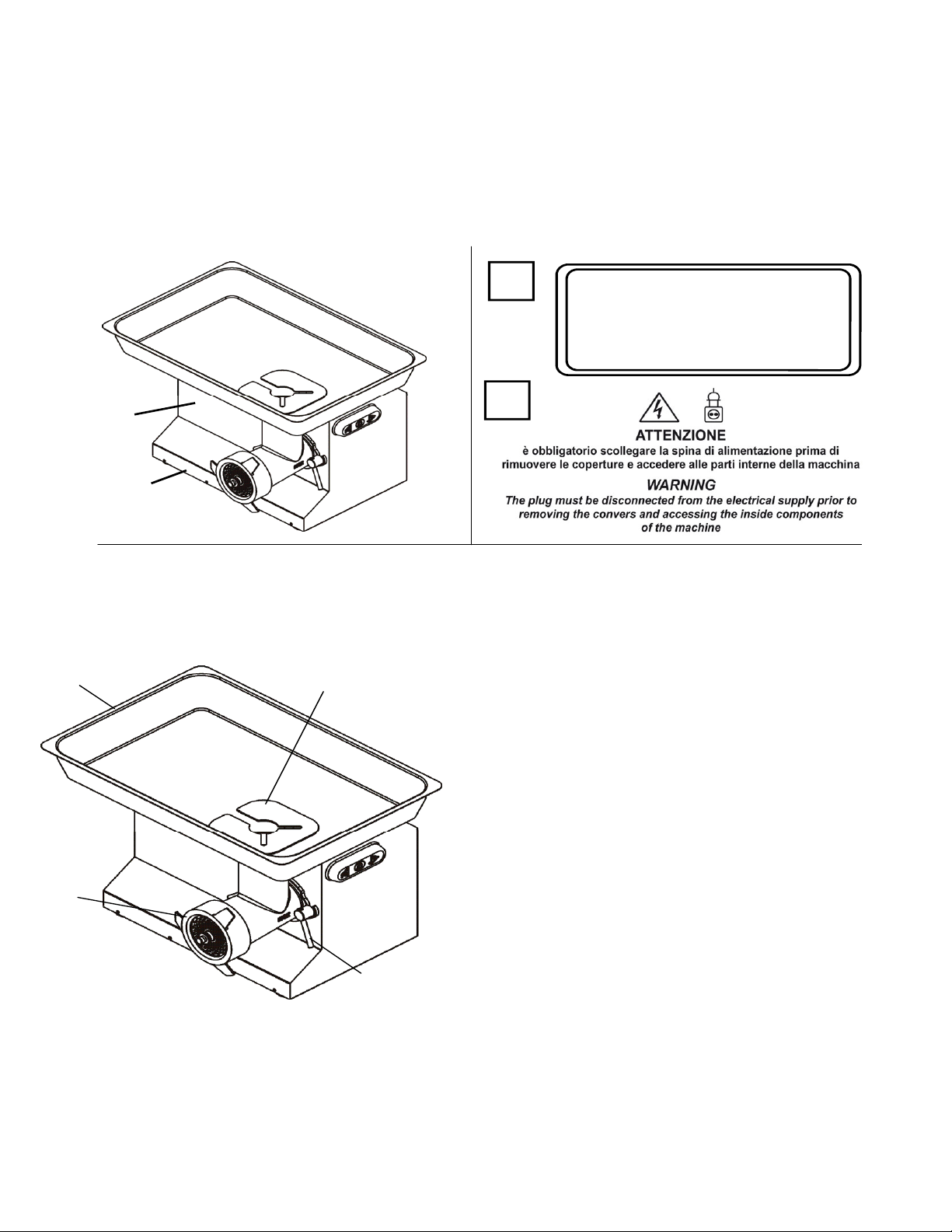
1.7.1 - Warning signs and danger (fig. 1.7.2)
WARNING! With the machine connected to the electricity mains, do not work on the
electrical components. There is a risk of electric shock. Follow the instruc-tions referred
to on the plates. Failure to comply may cause injury.
Make sure the plates are present and readable.
If not, apply or replace them.
1.8 – Protection and safety devices
WARNING! Before using the machine, check the correctness of the positioning of safety
devices and their integrity. Check their presence and efficiency at the begin-ning of each work
shift. If it is not right, contact the maintenance manager.
A CAUTION
IT IS PROHIBITED TO USE
AN OUT-PUT MEAT PLATE
WITH A HOLE EQUAL TO
OR GREATER THAN
8 mm WITHOUT
ADEQUATE PROTECTION
Fig. 1.7.2
B
A
B
2
3
1
Fig. 1.8.1
4
WARNING!
Do not tamper with the safety
devices for any reason.
1. Outlet feed of product, with holes in the bottom
plate up to 8 mm. In this case prevent the
introduction of the fingers inside the feed.
2. Stainless steel hopper rigidly set to the loading
feed.
3. Inlet lock nut. For correct operation of the meat
grinder, the inlet must be firmly tightened using
these lock nuts
4. Protective hand guard. The hopper, in the model,
shows the guard "2" Fig.1.8.1 rigidly fixed, in
accordance with the circular of the Ministry of
Labour and Social InsuranceNo. 66 of 05.09.79.
The smaller models do not require this guard due
to the small size of the loading feed

9
English
1.8.1 – Lock handle for meat output feed
Correct use:
To operate the machine correctly and obtain precise grinding, all meat grinders must have
the mouth rigidly locked.
It is important to observe the following procedure to prevent imprecise assembly:
1. Make sure that the machine is switched off.
2. Insert the mouth, including the ring nut and internal components (worm, knives, plates) into
the machine’s mouth support.
3. Make sure that it is in the correct position, with the milled rear end of the worm perfectly
slotted into the drive pin, then fasten it with the locking nuts (ref. 3 fig. 1.8.1). If it cannot be
fastened:
- loosen the ring nut, without removing it
- push the mouth until it adheres to the machine body
- take the worm pin and turn it until the screw inserts perfectly into the drive pin
- fasten the mouth with the locking nuts
- take the plate tang and turn it until it inserts precisely into the guide pins on themouth.
- tighten the ring nut fully
1.9 – Work position
The correct work position that the operator must occupy to
optimize the operation with the machine is shown in Fig. 1.9.1.
2 - Specifications
2.1 - Main parts
To facilitate understanding of the manual the main components of the machine are listed
below and shown in fig. 2.1.1.
Fig. 1.9.1
1
2
3
4
5
6
7
Fig. 2.1.1 1. Pestle is made of GUR HOSTALLOY 731
2. Stainless steel AISI 304 housing.
3. Machine controls
4. Feet
5. Output feed of ground meat is made of
stainless steel AISI 304.
6. Loading hopper is made of stainless steel
AISI 304.
7. Loading feed is made of stainless steel
AISI 304.
10
2.2 - Specifications
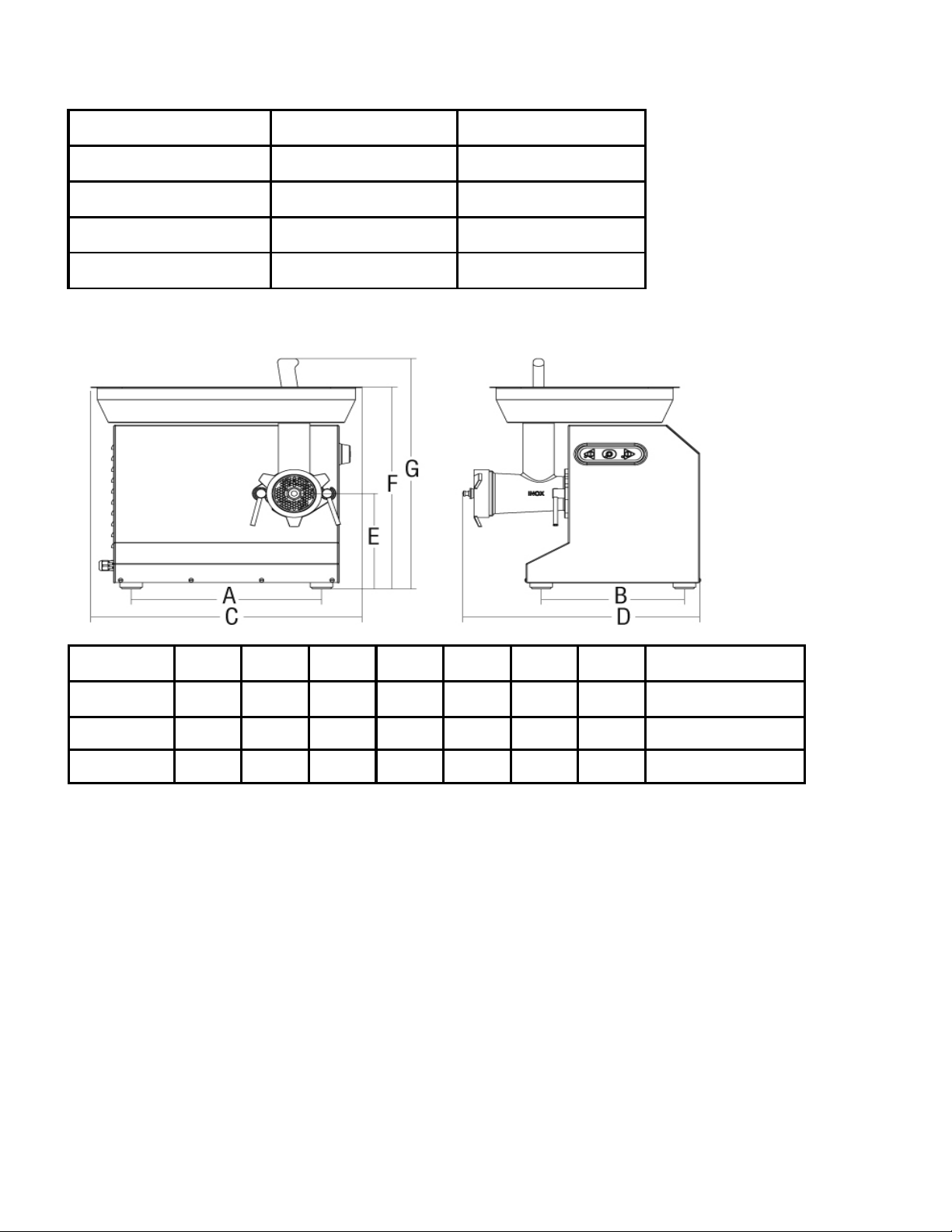
2.3 - Size and weight of the machine
TC 22 TC 32
Motor watt 1472/2 hp watt 2208/3 hp
Power source 230-400V/50Hz 230-400V/50Hz
Output/h 300 Kg/h 500 Kg/h
Standard plate ø 4,5 mm ø 6 mm
Fig. 2.3.1
A B C D E F G Net weight
mm mm mm mm mm mm mm kg
TC 22 351 264 500 437 132 430 491 32
TC 32 401 264 610 465 99 428 532 39
11
English
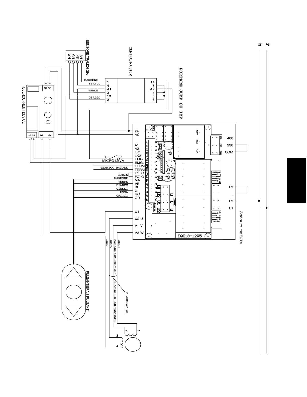
2.4 - Wiring diagrams
2.4.1 - Single-phase diagrams with electronic switch

12
2.4.2 - Three-phase diagrams with electronic switch

13
English
2.4.3 - Single-phase diagrams with stainless steel controls
14
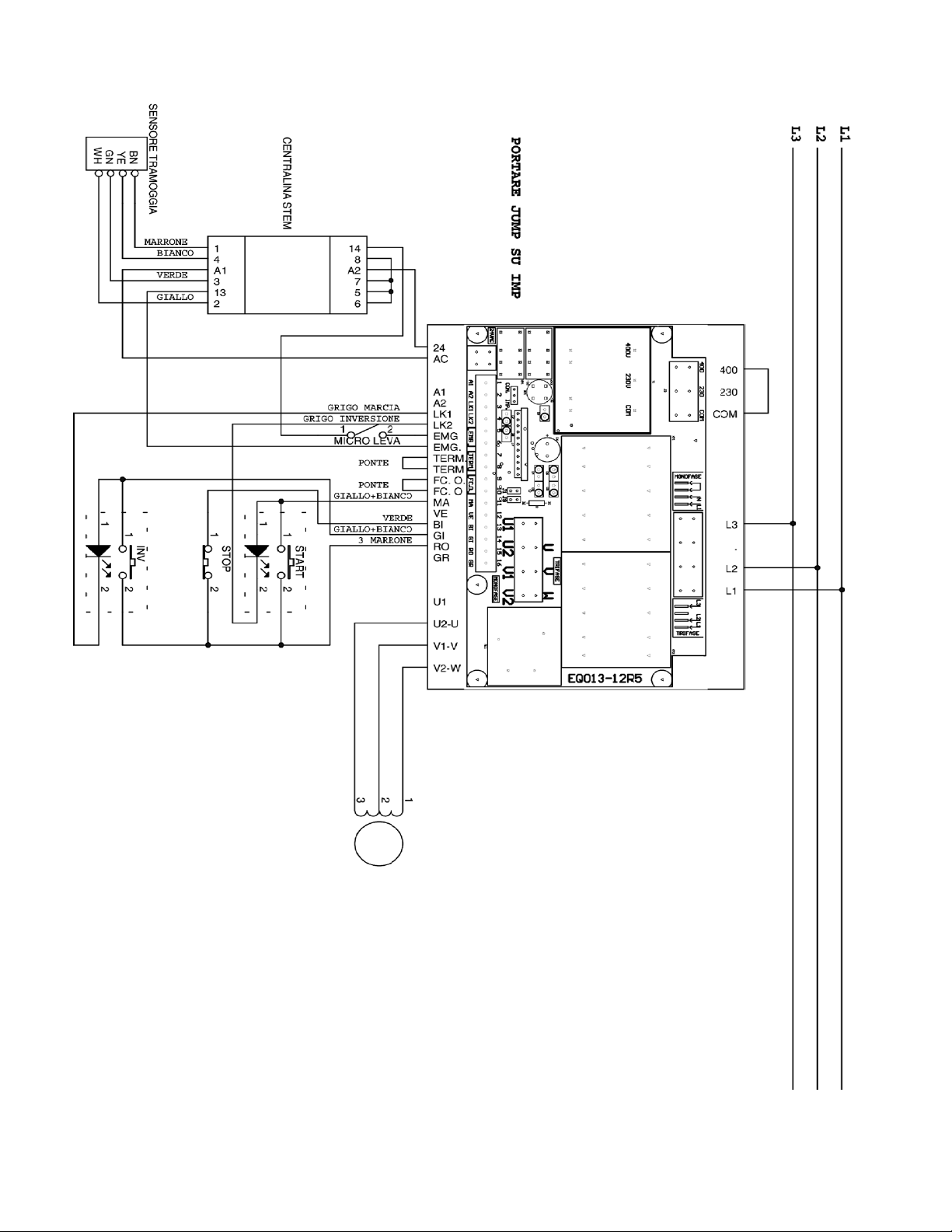
2.4.4 - Three-phase diagrams with stainless steel controls

15
English
4 - Testing, transport, delivery and installation
4.1 - Testing
The machine in your possession has been tested at our factory to ensure its smooth operation
and proper adjustment. During this testing, tests were conducted in operation on material
similar to that processed by the user.
4.2 - Delivery and handling of the machine
All the material shipped has been thoroughly checked before delivery to the carri-er. Unless
otherwise agreed with the customer, the machine is wrapped with nylon and strapped onto a
pallet; the carton sheathes it from above which will also be strapped on the pallet. Upon
receipt of the machine, verify the integrity of the pack-aging. If the packaging is damaged, the
carrier must sign the bill of receipt with a note such as " Accepted, with reservation ..." and
reason.
After opening the package, if damaged machine parts are present, make a claim to the carrier
within three days of the date indicated on the documents
.
4.3 - Installation
WARNING! The area where you plan to install the machine must be level, solid and on a flat
shoring and must ensure its support in safety. The machine must also be placed so as to
maintain ample space around it. This allows greater manoeu-vrability inthe work stages and
ensures access for subsequent maintenance. Pro-vide suitable lighting around the machine to
ensure proper visibility to the operator using the machine.
-emove the cellophane wrapping of the machine and any other packaging inside.
4.3.1 - Disposal of packaging
The packing materials such as cardboard, nylon, and wood products are compara-ble to
municipal solid waste. They can then be disposed of freely. The nylon mate-rial is a pollutant
that produces toxic fumes if burned. Do not burn and do not dis-perse but dispose of according
to applicable laws. If the machine is delivered in countries where there are special rules,
dispose of the packaging as required by the applicable legislation
.
Fig. 3.1.1
3
6
2
5
4
1
3 - Controls and Indicators
3.1 - List of controls and indicators
1 - Start button - Press to start the machine.
2 - Stop button - Press to stop the machine.
3 - Push button for reverse - Allows you to change
the direction of rotation of the rotor pulses..
4 - 5 - 6 - Lights

16
4.3.2 - Handling the machine
WARNING! Handle the machine with care and attention, avoiding accidental falls that could
damage it severely. To avoid muscle strain in liftingthe machine, lift using your legs.
4.4 - Connection to the electric mains
WARNING! Verify that the power supply line corresponds to the value on the nameplate of
the machine. Any operation should be performed solely byqualified personnel expressly
authorized by the manager in charge. Connect to a grid pro-vided with efficient grounding
plug.
4.4.1 - Three-phase machines, 380 Volt-50Hz and 220 Volt-50Hz In these
arrangements, the machine is supplied
with a power cord of a section 4 x 1.5 mm.
This is connected to a three-phase three-pole +
grounding plug. Connect the cable to the three-
phase power supply by putting a 16 Amp circuit breaker switch
.
4.4.2 - Single-phase machine 220 volt-50 Hz
In this arrangement, the machine is supplied with a power cord of
section 3 x 1.5 mm. This is connected to a single-phase three-
polar plug. Connect the cable to the single phase power supply 220 Volt-50 Hz by inserting a
16 Amp circuit breaker switch.
In installations with voltages other than those
mentioned above, please contact the manu-facturer.
If you need to lengthen the cord, use a cable of the
same section as the one installed by the
manufacturer.
5 - Starting and stopping
5.1 - Checking for correct wiring
Plug into the electrical socket;
The indicator light from the grid ("6" Figure 3.1.1) must be lit;
Press the button ("1" Figure 3.1.1), checking the direction of rotation of the uten-sils (in 380
three-phase version).
The direction of rotation must agree with the direction of the arrow(“C”, Fig. 1.7.2),
counterclockwise.
If the rotation direction is backward, disconnect the machine from electricity and contact our
dealer.
Note: For machines connected to a single-phase line and built at such a power, the correct
direction of rotation is determined by the manufacturer.

17
English
5.2 - Check for the presence and effectiveness of guards and safeties
- Th outlet feed of the product. Make sure that the outlet feed of the product has holes
with a diameter of less than 8 mm.
-H nd guard protection. The hopper must have hand guard protection
-Stai less steel hopper. The stainless steel hopper is solidly attached to the loading feed
5.3 - Check the efficiency of the stop button (fig. 5.3.1)
With the machine connected to the grid and the utensils
in motion, press the stop button (2). The machine must
stop.
5.4 - Starting the machine (fig. 5.3.1)
"1" Figure 5.3.1, after having properly connected the plug to the electric mains supply and the
machine is activated.
5.5 - Stopping the machine (fig. 5.3.1)
To stop the machine, press the stop button, "2" Fig 5.3.1 and the machine stops
6 - Using the machine
6.1 - Requirements
Requirements! Only authorized personnel can service the machine.
Before starting use the operator is required to ensure that all the guards are in place and that
the safety devices are in place and effective.
Otherwise, turn off the machine and contact the maintenance manager.
The product to be ground mustbe cut up to a size that can fit into the loading feed and must be
pressed with the aid of the special pusher (pestle) NEVER USE YOUR HANDS FOR THIS.
The machine is not designed to operate inside a cold room: this could seriously damage
the electrical components sensitive to condensate (which forms at low temperatures)
and also alter the viscosity ofthe grease and/or lubricating oil in the gearbox housed
inside it, jeopardising the machine’s correct operation and causing potential failures.
6.2 - Preparation of the output feed
The machine can be set to use three different meat cutting units: A -
Enterprise or normal
B - Partial UNGER
C - Total UNGER
-The system -C- (total UNGER),
includes: a AISI 304 stainless steel rotor "1"
to transport the meat,
a AISI 430 steel fringer plate
"2", a first knife "3" and the related perforated
plate "4" both in AISI 430 steel, a second
knife "5" with
the final perforated plate "6" both in AISI 430
steel, a spacer "7" in AISI 304 stainless steel.
Fig. 6.2.1
Fig. 5.3.1
To start the machine, just press the start button 1 2

18
-The system -B- (partial UNGER), replaces the knife "5" and plate "4" with the spacer "7".
-The system -A- (Normal) is the easiest method of transport, composed only of the AISI 304
stainless steel rotor, a knife and an output plate, both in AISI 430 steel.
It is not possible to mount the plates of the B or C unit on models with A grinder; it is necessary to
change the entire unit.
6.3 - Using the grinder
1 Make sure that the supply voltage matches the value on the rating plate. The voltage indicator
will be lit to indicate the connection to the electric grid.
2 Slightly tighten the ring nut of the meat grinder and put in some meat, press the start button,
making sure that the direction of rotation is the same as that indicated by the arrow
(counterclockwise).
3 If the meat output is cut well, the adjustment of the ring nut is fine, if not, tighten the ring nut
more until you get a perfect cut of meat.
4 Stop the machine by pressing the stop button
5 To loosen the ring nut it is not necessary to use a tool, simply turn the handle that locks the feed,
because the ring nut is free and can be easily extracted.
6 After a thorough cleaning, first mount the feed, making sure it is in the correct position and
secure it with the side handle.
7 Now you can reassemble the rotor, the knife, the plate and the ring nut.
6.4 - Dismantling and cleaning the mouth after use
1 Empty the mouth and inlet collar completely and then start the machine without any meat in it.
2 When you are sure that no processing residues are left in the collar and mouth, switch the
machine off and disconnect it from the mains electricity.
3 Loosen the nuts fastening the mouth.
4 Detach the mouth completely and place it on a support surface. You can now dismantlethe
components of the mouth.
5 Loosen the ring nut fully until it slides off.
6 Extract the plate and knives, followed by the worm.
7 Clean every component.
6.5 - Assembling the mouth after cleaning
After properly cleaning each component, reassemble the mouth:
1. Insert the grinding worm.
3. Insert the knife and plate, while making sure that the knife is mounted with the blade facing the
grinding plate.
4. Screw on the ring nut and tighten it slightly.
5. Mount the machine mouth by following the instructions in the relevant paragraph.

19
English
6.6 - Manual hamburger forming accessory
The meat grinder can be supplied with a manual hamburger forming accessory.
This accessory must be mentioned when order-ing
the machine, so that the latter can be fitted during its
assembly with:
- A: sensor that control the start/stop of the
meat grinder;
- B: a sensor that detects he presence of the hamburger forming
accessory, positioned inside the casing;
-C: ring-nut mount
-D: plate without tang;
-E: short worm pin.
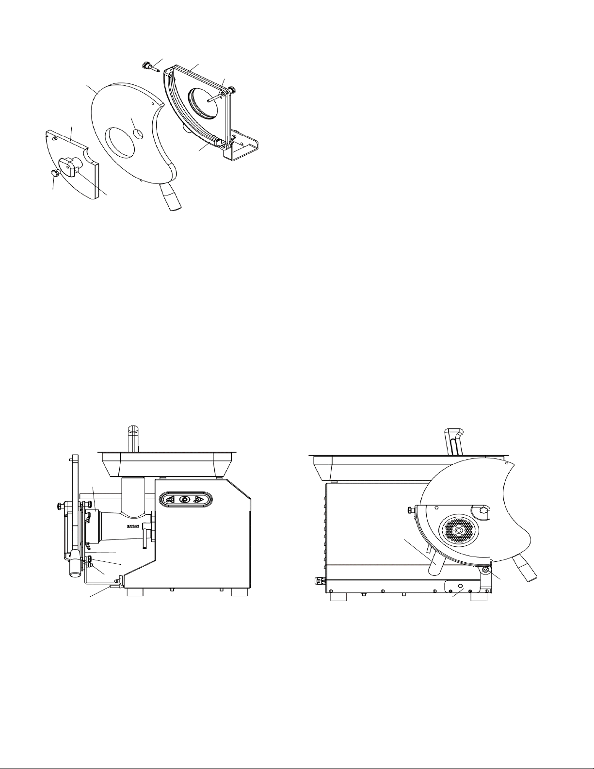
6.6.1 - Assembling the hamburger forming accessory
The hamburger forming accessory is supplied with all its parts dismantled. To
assemble it correctly, proceed as explained below.
PHASE 1
- Loos nthe knob (1)
- Loos nthe knob (2)
- Remove the aluminium central pin (3)
- Remove the plexiglass slab (4) closing the hamburger forming
accessory
PHASE 2 Attach the bracket (5) to the plate (6)
-Take a 5 mm Allen key and a 13 mm fixed spanner
-
-
Tighten the knob (7) onto the M6 pin (present on the plate)
Tighten
the M8x25 hexagon socket countersunk head screw (8) with the
relative M8 self-locking nut (9)
N.B: for the time being, only slightly tighten the knob (7), screw
(8) and nut (9).
Fig. 6.6.3
1
7
5
6
8
9
Fig. 6.6.4
Fig. 6.6.2
B
E
A
D
C
Fig. 6.6.1
2 3
4
20
PHASE 3
- Insert the PE500 olyethylene slider (9) inside the aluminium profile
(11).
-The threaded pin (18) must slot through the hole (19) in the slider.
-Insert the pl xiglass slab (4) into the aluminium profile (11), positioning
it above the slider (9).
-Attach the pl xiglass slab (4) to the plate (6):
- insert the k ob (1) through the slotted hole on the slab (4);
- tighten t e knob (1) fully;
- insert the a uminium block (3) through the hole (19);
-fasten the a uminium block (3) to the plate (6), tightening the knob (2)
to the threaded pin (18)
PHASE 4 Adjusting the hamburger forming accessory on the meat grinder:
- Take a 5 mm Allen key and a 13 mm fixed spanner
-Turn the lever (12) clockwise while holding the assembled hamburger forming accessory
-Attach the h mburger forming accessoryto the meat grinder, positioning it against the ring nut
(13), through the hole on the rear plate (6)
-Push it until the wo pins (14) present on the casing slide through the two holes on the bracket
(5)
-Turn the lever (12) clockwise to lock the accessory on the ring nut
-Tighten the knob (7) and screw (8) with the relative self-locking nut (9)
The hamburger forming accessory will now be ready for use.
6.6.2 - Using the hamburger forming accessory
After installing it correctlyand fastening it to the meat grinder, the hamburger form-ing accessory
can be used.
WARNING! The operator must supervise the hamburger forming accessory while it operates
and during the hamburger production process.
1
Fig. 6.6.5
9
11
4
6
3
18
19
2
Fig. 6.6.6
14
9 7
13
6
8
Fig. 6.6.7
12
5
21
English
- load the p oduct to be ground into the meat grinder’s hopper
-start the meat grin er by pressing the start button
-
the ground meat that comes out of the meat grinder’s mouth fills the hamburger die
-
-
visually inspect the process and remove the hamburger once it has been formed, by turning the
hamburger forming accessory slider anti-clockwise, holding it fromthe knob
only in this way will
the machine stop working and pushing the ground meat outwards
- after removi gthe hamburger from inside the die, put the slider back into place by
turning it clockwise, holding it from the knob
-this will cause the hamburger production cycle to resume
7 - Maintenance
7.1 - Requirements
WARNING! All the maintenance and cleaning must be performed with the machine at a
standstill, disconnected from the power mains. The area where maintenance operations are
performed must always be kept clean and dry.
Do not allow unauthorized personnel to service machinery.
Any replacement of parts, including replacement of the utensils must be made with original
parts from authorised shops or directly from the manufacturer.
7.1 - Lubrication
The machine does not require lubrication.
-
after removing the hamburger from inside the die, put the slider back into place by
turning it clockwise, holding it from the knob
-
this will cause the hamburger production cycle to resume
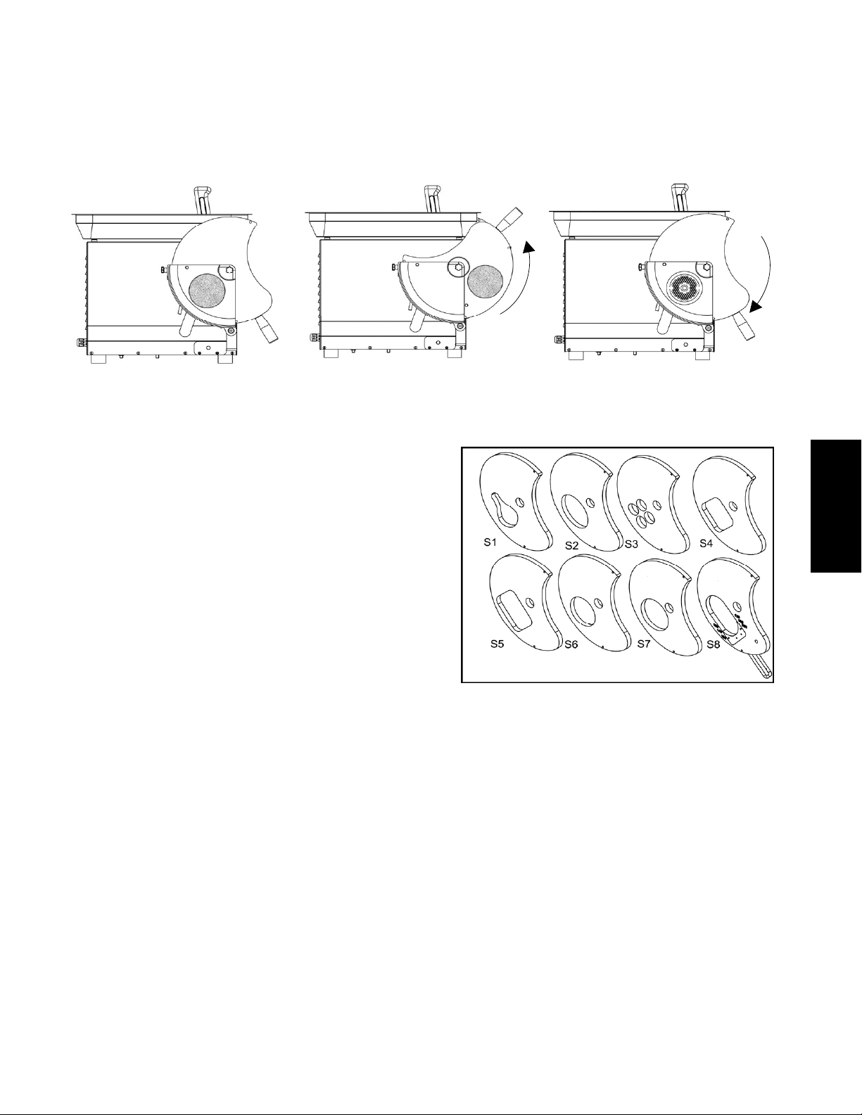
The sliders come with different dies for the hamburgers:
- S1 Chicken leg - approx. 105 g
- S2 Oval - approx. 130 g
- S3 Meat balls - approx. 20 (x4) g
- S4 Square - 100 x 100 mm - approx. 150 g
- S5 rectangular - 100 x 125 mm - approx. 190 g
- S6 Round - ø 110 mm - approx. 155 g
- S7 Round - ø 100 mm - approx. 140 g
- S8 Adjustable from round to oval - 100 g – 200 g
6.6.3 Detaching the hamburger forming accessory from
the meat grinder
- with the meat grinder switched off, raise the fastening lever and unlock the hamburger forming accessory
- hold the hamburger forming accessory with both hands and push it towards you
- remove it from the ring nut and from the two pins at the base of the casing
This manual suits for next models
1
Table of contents


