1/4
Thank you for choosing ENDA EDT5411A temperature controller.
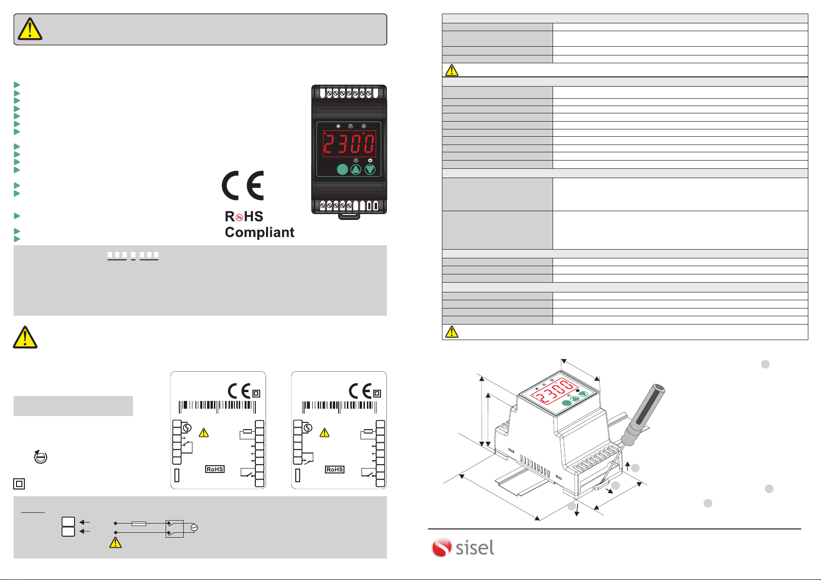
ENDA EDT5411A DIGITAL THERMOSTAT
54x94mm.
On-Off control.
Relay output for cooling or heating control.
Single NTC probe input.
Offset value can be entered for NTC input.
Compressor protection parameters can be entered.
In case of probe failure, output status can be set to
ON, OFF or periodic.
Upper and Lower setpoint value limits can be adjusted.
Defrosting duration and intervals can be adjusted.
6 Different warning tone selections.
Lower and upper alarm limit can be adjusted to depending
on set value.
Temperature unit can be selected °C or °F.
Digital input ;
- External alarm
- Initiate defrost
Transfer device parameter settings with ENDAKEY
- No power-up required.
RS485 ModBus protocol communication feature (optional).
CE marked according to European Norms.
Please read this document carefully before using this product. The guarantee will be invalidated if the device is
damaged by not following instructions detailed in the manual. The company shall not be responsible for any damage
or
losses however
caused,
which may
be experienced
as a
result of
the installation or
use
of
this
product.
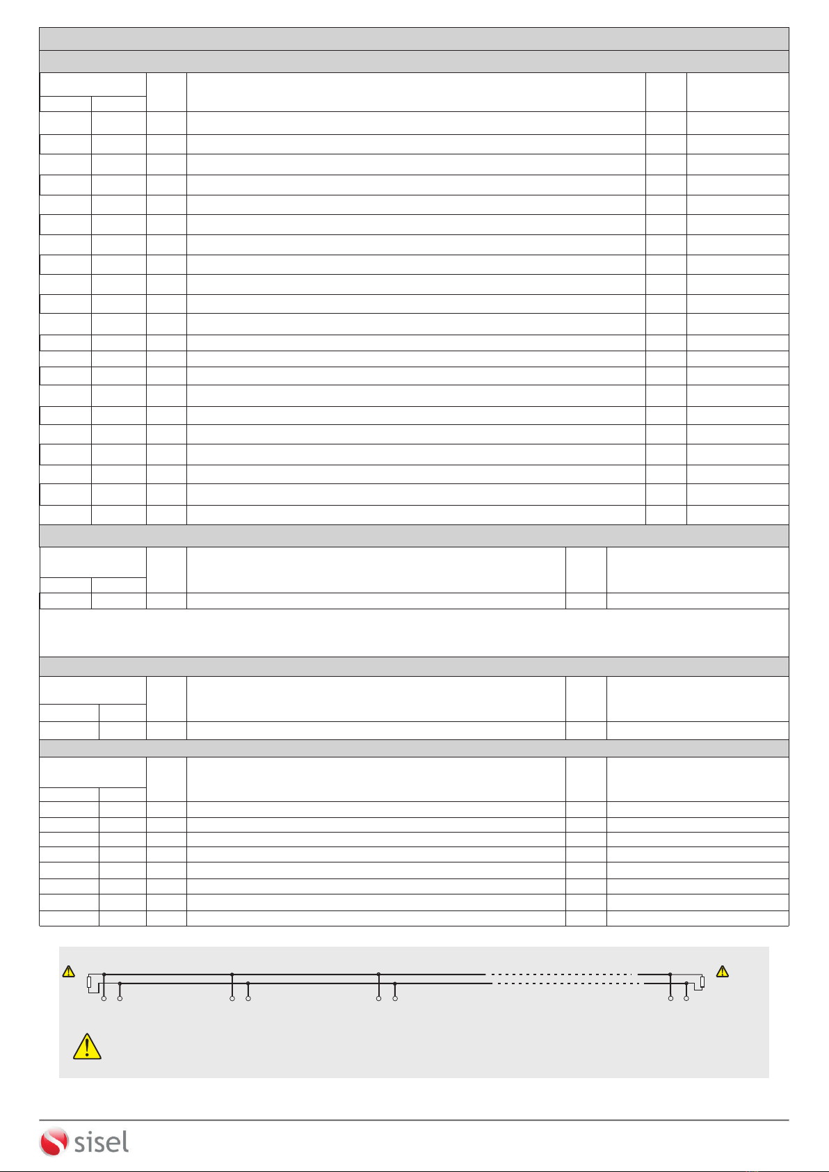
CONNECTION DIAGRAM
ENDA EDT5411A is intended for installation in control panels. Make sure that the device is used
only for intended purpose. The electrical connections must be carried out by a qualified staff
and must be according to the relevant locally applicable regulations. During an installation, all of the cables that are
connected to the device must be free of electrical power. The device must be protected against inadmissible humidity,
vibrations, severe soiling and make sure that the operation temperature is not exceeded. The cables should not be
close to the power cables or components.
SUPPLY:
NOTE:
184-253V AC
50/60Hz 4VA
Line
Neutral
230V AC
Supply
Switch
Note:
Cable size: 1,5mm²
Fuse
F 100 mA
250V AC
Fuse should
be connected
1) Mains supply cords shall meet the requirements of
IEC 60227 or IEC 60245.
2) In accordance with the safety regulations, the power
supply switch shall bring the identification of the
relevant instrument and it should be easily
accessible by the operator.
10
11
Order Code : EDT5411A - - -
1 2 3
1 - Supply Voltage
230........230V AC
110.........110V AC
24........24V AC/DC
12........12V AC/DC
SM........9-30VDC / 7-24V AC
2-Output
R......... 8A Relay output
P......... 20A Relay output
3 - Modbus
RS........ RS-485 Modbus Available
(Optional / Specify at order)
Blank.... N/A
Holding screw
0.4-0.5Nm
Equipment is protected throughout
by DOUBLE INSULATION.
ENVIRONMENTAL CONDITIONS
Height Max. 2000m
Ambient / Storage Temperature
Relative Humidity
0 ... +50°C/-25 ... 70°C (without icing)
Protection Class According to EN60529; Front panel : IP65, Rear panel : IP20
Supply Voltage
230V AC / 110V AC +%10 -%20 50/60Hz ; 12V AC/DC ± %10 ,24V AC/DC ±%10 or 9-30V DC / 7-24V AC SMPS.
Power Consumption Max. 5VA
2.5mm² screw-terminal connections
±1%
4 Digits, 12.5mm, 7 Segment Red LED
Connection
Scale
Sensitivity
Accuracy
Time Accuracy
Display
EMC
Safety Requirements
EN 61326-1: 2013
EN 61010-1: 2010 (Pollution degree 2, overvoltage category II)
ELECTRICAL CHARACTERISTICS
-60.0 ... +150.0°C (-76.0 ... +302.0°F)
0.1°C (Can be selected as 0.1ºC or 1ºC.)
±1°C
CONTROL
Control Type Single set-point control
On-Off control
Control Algorithm
Hysteresis Adjustable between 1 ... 20.0 °C.
Life Expectancy for Relay
OUTPUTS
HOUSING
Housing Type Suitable for flush -panel mounting
Dimensions W54xH94xD68mm
Weight Approx. 190g (After packing)
Enclosure Material Self extinguishing plastics.
Relay Output
For EDT5411A-X-R ; Without load 30.000.000 mechanical;
250V AC, 8A resistive load 100.000 electrical operation.
For EDT5411A-X-P ; Without load 10.000.000 switching;
277V AC,20A (for resistive load) 100.000 electrical operation.
For EDT5411A-X-R ; Relay : NO+NC 250V AC,8A (resistive load),
1/2HP, 0.37KW 240V AC (inductive load)
For EDT5411A-X-P ; Relay : NO 277V AC,20A (resistive load),
1/2HP, 0.37KW 250V AC (inductive load)
Max. humidity 80% for temperatures up to 31°C decreasing linearly to
50% relative humidity at 40°C.
INDUSTRIAL ELECTRONICS
EDT5411A-230-R-RS
DIGITAL THERMOSTAT
SN: XXXXXXXXX
ENDA
ENDAKEY
COMPRESSOR
250V AC 8A
RESISTIVE LOAD
15 14 13 12 11 10
1234567 8 9
230V AC +10% -20%
50/60Hz 5VA
NTC
GND
COM
B
A
GND
DIG INP
Made in Turkey
INDUSTRIAL ELECTRONICS
EDT5411A-230-P-RS
DIGITAL THERMOSTAT
SN: XXXXXXXXX
ENDA
ENDAKEY
COMPRESSOR
250V AC 20A
RESISTIVE LOAD
15 14 13 12 11 10
1234567 8 9
230V AC +10% -20%
50/60Hz 5VA
NTC
GND
COM
B
A
GND
DIG INP
Made in Turkey
DIMENSIONS
To removing the device from rail ;
Push the rail lock in direction 2 with a
screwdriver and pull the device in
direction 3 .
To mounting the device to the panel ;
Push the device in direction 1 , the rails
provide the key to keeping the rail.
CAL
EDT5411A
°C
1 2 3 4 56789
1817
1615
14
13
12
11
10
ENDA
EDT5411A SET
°C
°F
EDT5411-EN-01-191216
SİSEL MÜHENDİSLİK ELEKTRONİK SAN. VE TİC. A.Ş.
Şerifali Mah. Y.Dudullu 34775
ÜMRANİYE/İSTANBUL-TURKEY
Tel : +90 216 499 46 64 Pbx. Fax : +90 216 365 74 01
url : www.enda.com.tr
Barbaros Cad. No:18 ENDA
TM
Please see page 4 for
Modbus Connection Diagram
KEEP AWAY device from exposed to corrosive, volatile and flammable gases or
liquids and DO NOT USE the device in similar hazardous locations.
Avoid any liquid contact when the device is switched on.
DO NOT clean the device with solvent (thinner, gasoline, acid etc.) and / or abrasive cleaning agents.
3
2
68mm
94mm
54mm
1
46mm
46,5mm
CAL
EDT5411AA
°C
ENDA
EDT5411A SET
°C
°F
1
2
3
1
2
3