Thank you for choosing ENDA ET2413K incubator temperature controller devices.
1/3
CONTROL
8 9 10
NTC
GND
11 12
1 2 3 4 5 6 7
ENDA INDUSTRIAL ELECTRONICS
SN: XXXXXXXXX
ET2413K-230
DIGITAL DEFROST
THERMOSTAT
ENDAKEY
230V AC +10% -20%
50/60Hz 5VA
ROTATE
250V AC 8A
HUMIDIFIER
250V AC 8A
HEAT
250V AC 8A
RESISTIVE
LOAD
1 2 3 4 5 6 7 8 9 10
ENDA INDUSTRIAL ELECTRONICS
ET2413K-24-RS
DIGITAL DEFROST
THERMOSTAT
ENDAKEY
NTC
GND
11 12 13
COM
B
A
ROTATE
250V AC 8A
HUMIDFIER
250V AC 8A
HEAT
250V AC 8A
RESISTIVE
LOAD
24V AC/DC ±10%
50/60Hz 5VA
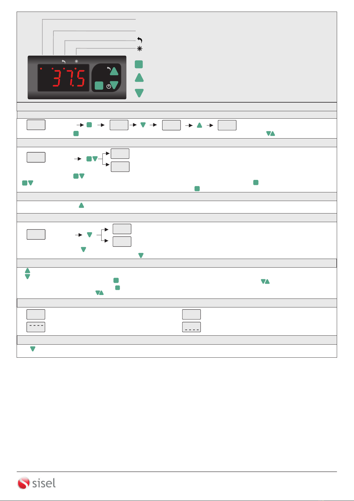
SET
SET
ET2413K
ENDA
°C
°F
RH
77mm
35mm
SET
SET
ET2413K
ENDA
°F
°C
RH
Made in Turkey
Made in Turkey
8 9 10
NTC
GND
11 12
1 2 3 4 5 6 7
ENDA INDUSTRIAL ELECTRONICS
SN: XXXXXXXXX
ET2413K-24
DIGITAL DEFROST
THERMOSTAT
ENDAKEY
ROTATE
250V AC 8A
HUMIDIFIER
250V AC 8A
HEAT
250V AC 8A
RESISTIVE
LOAD
8 680407 711291
24V AC/DC ±10%
50/60Hz 5VA
Made in Turkey
1 - Supply Voltage
230........230V AC
24 ........24V AC/DC
12 ........12V AC/DC
2 - ModBus (Optional)
RS.........ModBus
Blank.....N/A
Order Code : ET2413K -
12
ET2413K-EN-01-170327
ENDA
TM
SİSEL MÜHENDİSLİK ELEKTRONİK SAN. VE TİC. A.Ş.
Şerifali Mah. Y.Dudullu 34775
ÜMRANİYE/İSTANBUL-TURKEY
Tel : +90 216 499 46 64 Pbx. Fax : +90 216 365 74 01
url : www.enda.com.tr
Barbaros Cad. No:18
35x77mm sized
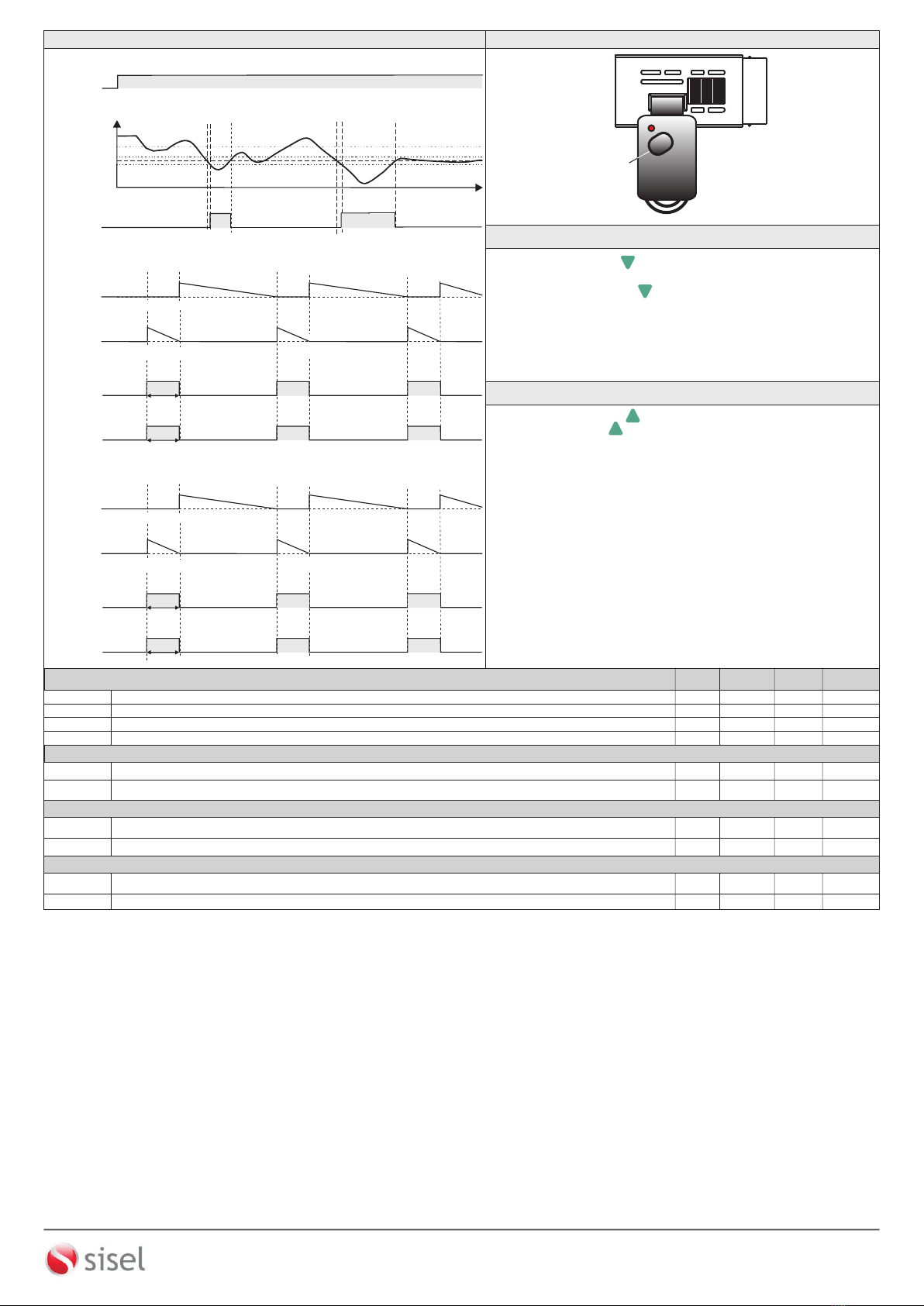
On-Off control.
Relay output for heating operation
Single NTC probe input
Offset value can be adjusted for NTC input
Upper and Lower setpoint value limits can be adjusted.
Rotation duration and intervals can be adjusted
Manuel process feature
Humidity duration and intervals can be adjusted
Temperature unit can be selected °C or °F.
Transfer device parameter settings with ENDAKEY
- No power-up required
RS485 ModBus protocol communication feature (optional)
CE marked according to European Norms.
ENDA ET2413K DIGITAL THERMOSTAT
Please read this document carefully before using this product. The guarantee will be invalidated if the device is
damaged by not following instructions detailed in the manual.
The company shall not be responsible for any damage or
losses
however
caused,
which may be
experienced as
a
result
of
the
installation
or
use
of
this
product.
ENDA ET2413K is intended for installation in control panels. Make sure that the device is used
only for intended purpose. The electrical connections must be carried out by a qualified staff
and must be according to the relevant locally applicable regulations. During an installation, all of
the cables that are connected to the device must be free of electrical power.
Holding screw
0.4-0.5Nm.
Equipment is protected throughout by
DOUBLE INSULATION
SUPPLY:
NOTE:
184-253V AC
50/60Hz 4VA
Line
Neutral
230V AC
Supply
Switch
Note:
Cable size: 1,5mm²
Fuse
F 100 mA
250V AC
Fuse should
be connected
1) Mains supply cords shall meet the requirements of
IEC 60227 or IEC 60245.
2) In accordance with the safety regulations, the power
supply switch shall bring the identification of the
relevant instrument and it should be easily
accessible by the operator.
6
7
ENVIRONMENTAL CONDITIONS
Ambient / Storage Temperature
Relative Humidity
Protection class
Height
Do not use the device in locations subject to corrosive and flammable gasses.
ELECTRICAL CHARACTERISTICS
Supply Voltage
Power Consumption
Connection
Scale
Sensitivity
Accuracy
Time Accuracy
Display
EMC
Safety Requirements
OUTPUTS
Rotation Relay Output
Heat Relay Output
Humidification Relay Output
LIFE EXPECTANCY FOR RELAYS
Heat Relay
Rotation Relay
Humidification Relay
Control Type
Control Algorithm
Hysteresis
HOUSING
Housing Type
Dimensions
Weight
Enclosure Material
Max. 2000m
0 ... +50°C/-25 ... 70°C (without icing)
According to EN60529; Front panel : IP65
Rear Panel : IP20
Relative humidity 80% for temperatures up to 31°C decreasing linearly to 50% relative humidity at 40°C.
Max. 5VA
2.5mm² screw-terminal connections
±1%
4 digits, 12.5mm, 7 segment LED
EN 61326-1: 2013
EN 61010-1: 2010 (Pollution degree 2, overvoltage category II)
-60.0 ... +150.0°C (-76.0 ... +302.0°F)
0.1°C (Can be selected as 0.1ºC or 1ºC.)
±1°C
230V AC +%10 -%20, 50/60Hz ; 12V AC/DC ± %10 or 24V AC/DC ±%10
NO 250V AC, 8A ( ), 1/2hp, 0.37kW 240V AC ( )
+NC for resistive load for inductive load
NO 250V AC, 8A (for resistive load), 1/2hp, 0.37kW 240V AC (for inductive load)
NO 250V AC, 8A (for resistive load), 1/2hp, 0.37kW 240V AC (for inductive load)
Without load 30.000.000 switching; 250V AC, 8A (resistive load) 100.000 switching.
Without load 30.000.000 switching; 250V AC, 8A (resistive load) 100.000 switching.
Without load 30.000.000 switching; 250V AC, 8A (resistive load) 100.000 switching.
Single set-point control
On-Off control
Adjustable between 1 ... 20.0 °C.
Suitable for flush -panel mounting
W77xH35xD61mm
Approx. 190g (After packing)
Self extinguishing plastics.
While cleaning the device, solvents (thinner, gasoline, acid etc.) or corrosive materials must not be used.
DIMENSIONS
Note:
1) Panel thickness should
be maximum 7mm.
2) If there is no 60mm free
space at the back side of
the device,it would be
difficult to remove it from
the panel.
Flush mounting
clamp
For removing mounting clamps:
- Push the flush-mounting
clamp in direction 1 as shown
in the figure below.Then,pull
out the clamp in direction 2 .
71,5mm
28,5mm
Panel cut-out
61mm 5mm
Flush mounting
clamp Panel Rubber
packing
2
Depth
1