Sissel Hang Up User manual

SISSEL®Hang Up
Die hochbelastbare Inversionsbank
The extremely robust inversion table
Table d’inversion. Qualité et robustesse
Tabla inversora muy robusta
Gebrauchsanweisung
Instructions for use
Manuel d’utilisation
Manuel de instrucciones

AG 02 V4 22 / 80
Seite / Page 22
Dear Customer
Thank you for purchasing a SISSEL- inversion table. A good decision for yourself, your
health, your fitness and your sense of wellbeing, as well as the prevention of potential
ailments. This apparatus enables you to do the exercises necessary to improve your
cardiovascular system and strengthen your musculature in the comfort of your own home.
Please observe the instructions for use closely and follow the procedure described to
assemble the table. Should you still have legitimate cause for complaint, please contact us.
Enjoy this product. We wish you every success with your exercises.
SISSEL GmbH
First things first:
The device is intended for private or domestic purposes, not for professional use.
The device satisfies the requirements of DIN 957-2 Class H. The Class H range of applications
denotes home use. Class H training devices are not intended for installation in areas to which
uncontrolled access is allowed.
The product has been tested to DIN EN 957 for a max. user weight of 110 kg.
The manufacturer guarantees this product to be free of material and functional defects subject to
being used for its intended purpose and assembled and operated in compliance with the
instructions for use. The manufacturer's liability under the warranty is limited to the free
replacement or repair of parts that exhibit defects when used for their intended purpose.
The warranty does not cover damage caused by improper operation, wrongful use, unauthorised
repairs or commercial application.

AG 02 V4 23 / 80
Seite / Page 23
Safety instructions
1. Please read the instructions carefully prior to assembly.
2. Use the device only on an unobstructed, even surface
3. Make sure there is adequate free space to assemble the device.
4. Keep hands and feet away from moving parts during operation
5. Do not place any objects in openings.
6. Children should not be allowed near the device unsupervised. Their natural play
instinct may encourage them to use the device in a manner for which it is not
intended, causing accidents in the process.
7. Parents and other minders should be aware of their responsibility, since children's
natural instinct to play and experiment can lead to situations and behaviour for which
these training devices are not built.
8. If you allow children to train on the device, you should consider their mental and
physical development and above all their temperament. Should the situation arise,
supervise children and, more importantly, instruct them how to use the device
correctly. The devices must never be used as toys. Please note that the minimum
user height is 140 cm, the maximum 198 cm.
9. Check the device for damage and wear on a regular basis. Faulty parts must be
replaced immediately. Do not use the device again until its safety is guaranteed.
Pay particular attention to the following parts when checking:
Mounting of the table on the frame (e.g. bolts, pins, guides), foot mounting (e.g. tight
fit of screws and nuts, spring buttons)
Table (e.g. cracks)

AG 02 V4 24 / 80
Seite / Page 24
Always consult your doctor before starting an exercise programme, especially if you
are experiencing ill health.
Please note that exercising incorrectly or excessively can damage your health.
As with all sports and gymnastic activities, you should confirm whether and how to exercise
as soon as you experience physical discomfort, illness or other problems. Consult your
doctor or therapist if necessary.
However, if you suffer from the following complaints, illnesses or conditions, you should not
use the SISSEL- inversion table or use it only after consulting your doctor:
Hernia
Glaucoma, detachment of the retina, eye diseases
Osteoporosis, recently healed fractures or bones that contain
implants
Inner ear diseases, predisposition to head bleeding
Spinal injuries
Strokes, cardiovascular disorders, high blood pressure
Taking anticoagulants (heparin)
Swelling of the joints
Pregnancy
You should always consult your doctor if you are carrying an injury, have just had
an operation or suffer from organic diseases, cardiovascular complaints or other
health problems.
"Used sensibly, the inversion table brings enormous benefits and carries no more
risk than other popular and prevalent exercise, training and fitness activities"
AG 02 V4 25 / 80
Seite / Page 25
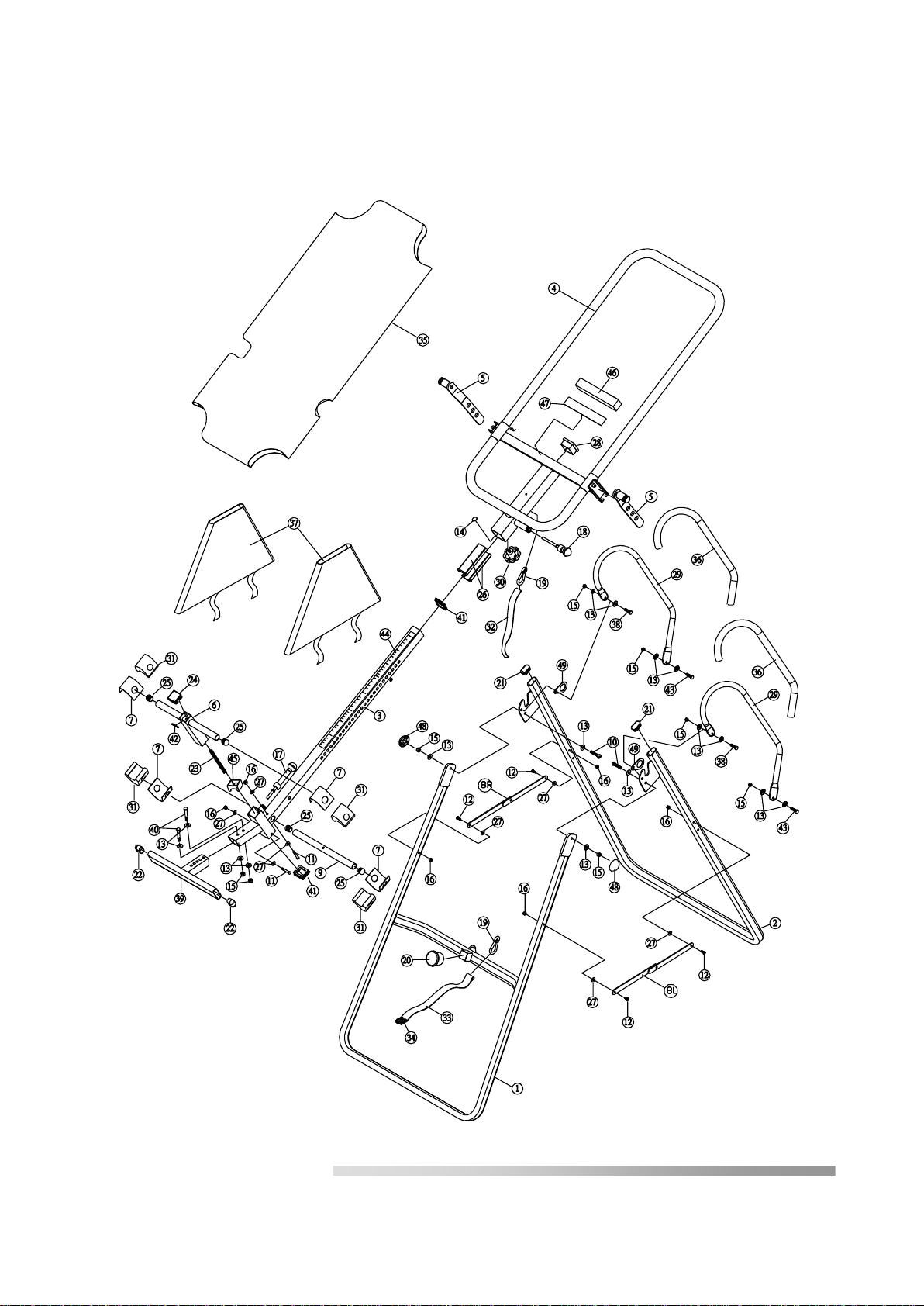
Exploded view
Parts overview

AG 02 V4 26 / 80
Seite / Page 26
Parts list
Code Description Qty
1 Front U-frame 1
2 Rear U-frame 1
3 Adjustable arm 1
4 Table frame 1
5 Pivot arm with position openings 2
6 Adjustable instep frame 1
7 Steel Heel Holder Bracket 4
8R Right Folding Arm 1
8L Left Folding Arm 1
9 Bars 1
10 Hex-head screw M8 x 23mm 2
11 Hex-head screw M6 x 47mm 2
12 Cross-head screw M6 x 30mm 4
13 Washers Ø20*Ø8.5*1.5 16
14 Cross struts 1
15 Counternut M8 8
16 Counternut M6 6
17 Small spring button 1
18 Large spring button 1
19 Safety hook (karabiner) 2
20 Rubber mount 1
21 Round end cap 2
22 Foot bar end cap 2
23 Spring 1
24 Square end cap 1
25 Round end cap 4
26 Guide bush for table frame 2
27 Washer Ø16*Ø6.5*1.0 8
28 End cap 1
29 Bar grip 2
30 Knob 1
31 Rubber Heel Holder 4
32 Nylon strap 1
33 Nylon strap 1
34 Strap buckle 1
35 Nylon lining / table 1
36 Foam grip 2
37 Protective cover 2
38 Hex-head screw M8 x 23mm 2
39 Foot rest 1
40 Hex-head screw M8 x 50mm 2
41 Square end cap 2
42 Spring washer 1
43 Hex-head screw M8 x 38 mm 2
44 Length adjustment scale 1
45 Plastic bushes 1
46 Foam pad 1
47 Double-sided adhesive tape 1
48 End cap Ø27*Ø13.5 2
49 Pivot arm ring 2

AG 02 V4 27 / 80
Seite / Page 27
Parts packing list
Code Description Qty
11 Hex-head screw M6 x 47mm 2
13 Washers Ø20*Ø8.5*1.5 12
15 Nut M8 6
16 Nut M6 2
27 Washer Ø16*Ø6.5*1.0 4
38 Hex-head screw M8 x 25mm 2
40 Hex-head screw M8 x 50mm 2
41 Square end cap 1
43 Hex-head screw M8 x 38mm 2
48 End cap Ø27*Ø13.5 2
49 Pivot arm ring 2
Double ended wrench 2
M 12 / M 14
Phillips Screwdriver 1
Note:
These parts are packed separately and will be required for assembly. Please check that all parts
are present before starting assembly.
All other parts are premounted.
Remove the packaging and place all parts within easy reach. Use the parts list to help you identify
the individual parts.
Now proceed as follows to assemble
48
49
AG 02 V4 28 / 80
Seite / Page 28
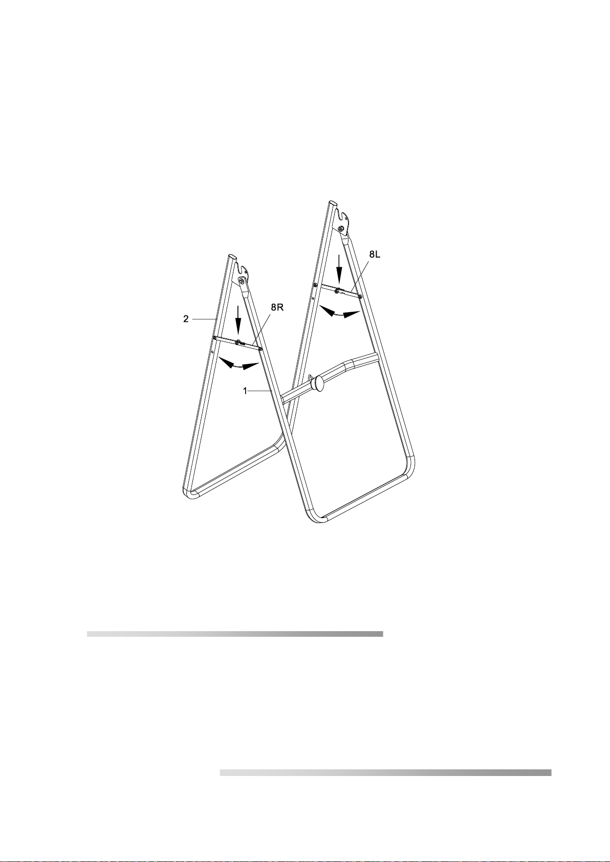
Assembly instructions
Step 1
Stand up the base of the machine by separating the u-frames. Pull the Front and Rear
U-Frames (1, 2) as far apart from each others as possible. Then push down on the middle of
the Left and Right Folding Arms (8L, 8R) until they are fully locked down.
Front
Back
AG 02 V4 29 / 80
Seite / Page 29
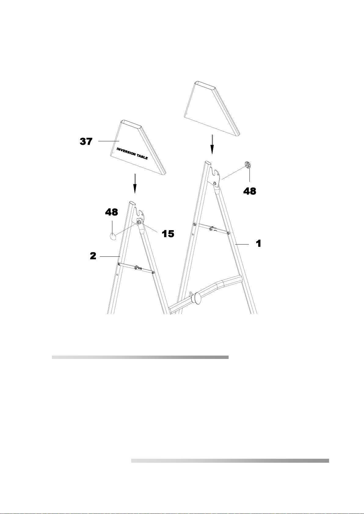
Step 2
Push the two cover caps (48) onto the nuts (15). Slide the protective covers (37), as shown, on
each side of the base and pull them down until the bottom edges of the covers are positioned just
below the left and right folding arms (8L, 8R). Close the Velcro(R) strips on the underside of the
protective covers (37) so that the covers are fastened to the left and right folding arms (8L, 8R).
The covers are correctly fitted if the left and right folding arms (8L, 8R) are completely inside the
protective covers (37). The logo will be on the outside.
AG 02 V4 30 / 80
Seite / Page 30
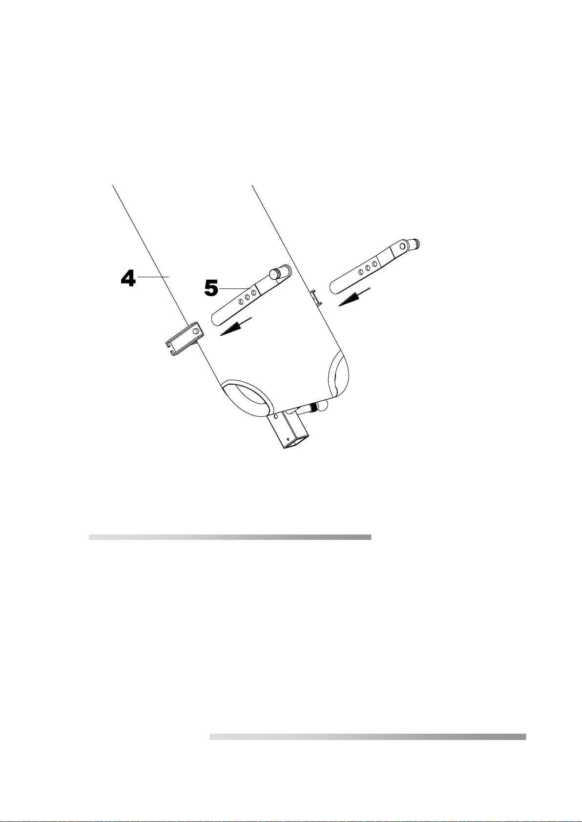
Step 3
Slide the lower end of the pivot arm (5) from above into the retainers attached to each side of
the table. The axis must be pointing outwards and the table upwards (nameplate on top).
Slide each of the pins into one of the three position openings in the pivot arm. The positions
must be the same on both sides.
TIP: Start with the lower position opening until you are familiar with the device.

AG 02 V4 31 / 80
Seite / Page 31
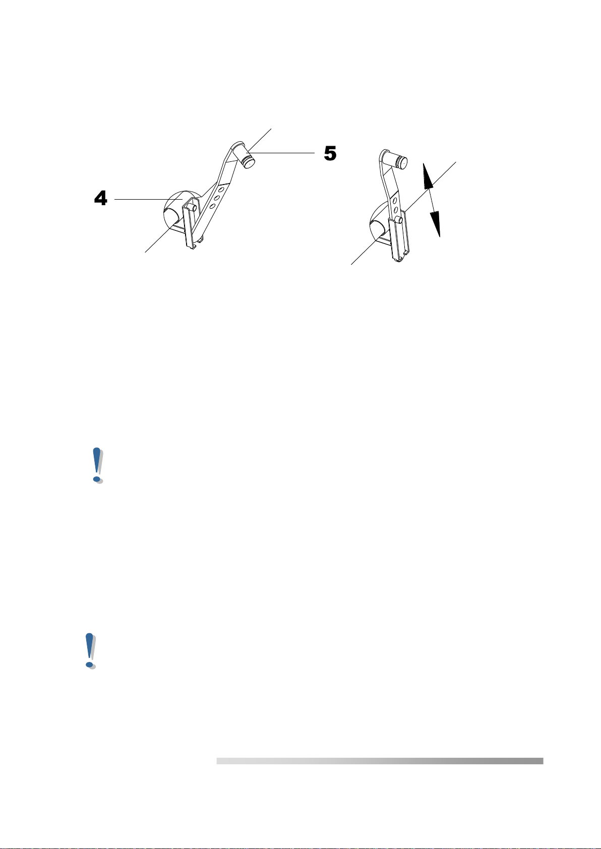
Step 4
Attach the pivot arm rings (49) to the pivot arms (5), see Fig. A + B. Mount the table frame
(4) onto the rear U-frame (2) by inserting the ends of the pivot arms (5) into the notch in the
plates. The grooved part of the bolt at the end of the pivot arm (5) must be located inside the
notch.
AG 02 V4 32 / 80
Seite / Page 32
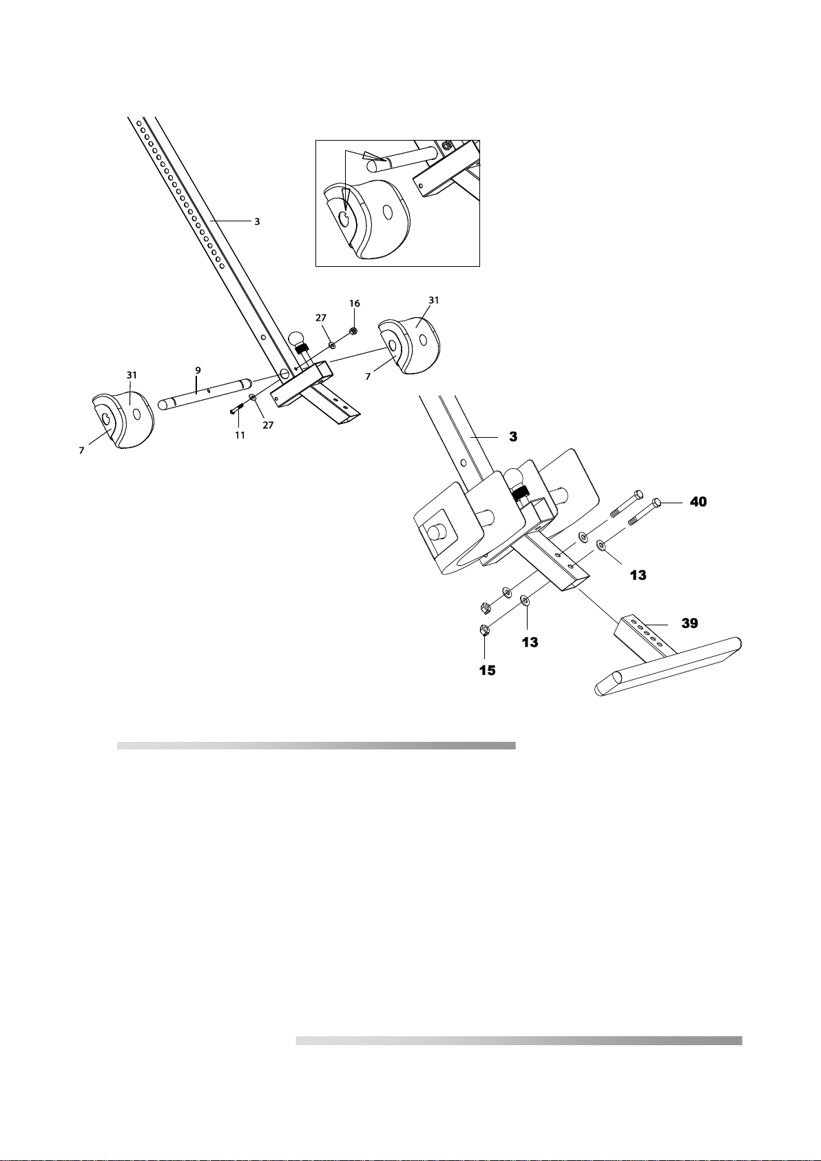
Step 5
Slide the Rod (9) through the large round hole on the side of the Adjustable Boom (3) and
secure the Rod (9) on the Adjustable Boom (3) with one M6x47 Hex Head Bolt (11), one M6
Lock Nut (16) and two Ø 16xØ 6.5x1.0 Washers (27). Slide one Steel Heel Holder Bracket (7)
and one Rubber Heel Holder (31) onto one end of the Rod (9) until the lock tooth is wedged into
the slot in the Rod (9) as shown in small figure. Use the same procedure to attach the other
Steel Heel Holder Bracket (7) and Rubber Heel Holder (31) onto the other end of the Rod (9).
Note: Make sure the lock teeth are wedged into the slots in the Rod (9) to lock the Steel Heel
Holder Brackets (7) and Rubber Heel Holders (31) in place before use.
Slide the bar of the foot rest (39) into the lower end of the adjustable arm (3) and line up two of
the holes in the bar of the foot rest (39) with two holes in the arm. Secure the bar of the foot rest
(39) in this position using two hex-head screws (40), nuts (15) and four washers (13).
The angle of the foot bar cross-tube must be equal to the angle at the slanted end of the arm.
AG 02 V4 33 / 80
Seite / Page 33
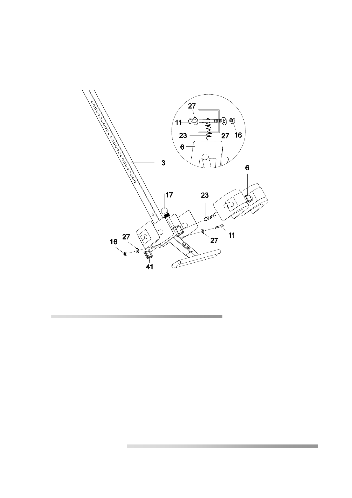
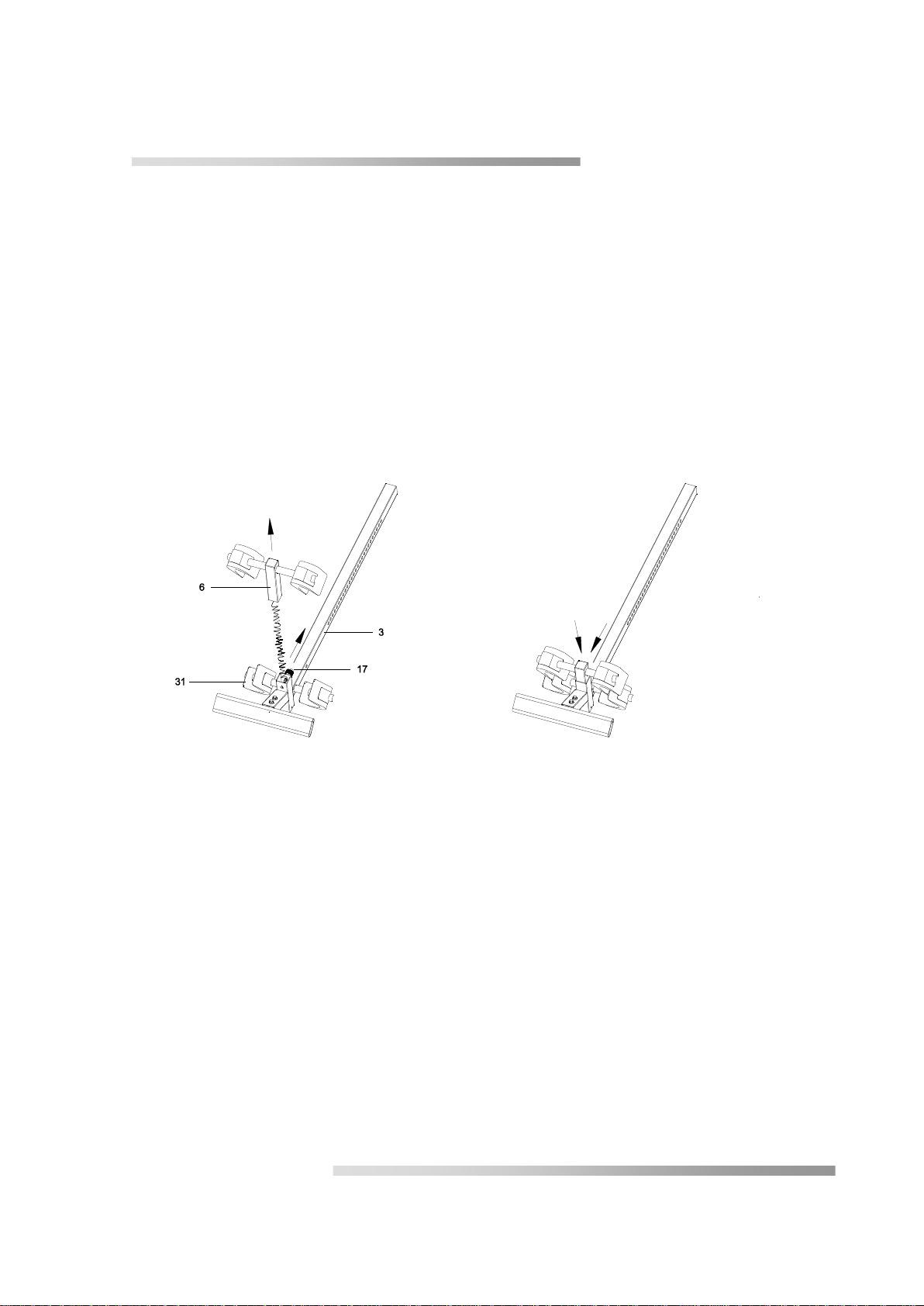
Step 6
Attach the Adjustable Instep Frame (6) to the Adjustable Boom (3) by inserting the Adjustable Instep
Frame (6) into the square bracket on the boom. Slide the Adjustable Instep Frame (6) completely into
the square bracket, insert the M6x47 Hex Head Bolt (11) with a Ø16xØ6.5x1.0 Washer (27) halfway
through the square bracket, slide the M6x47 Hex Head Bolt (11) through the ring at the bottom of the
Spring (23), slide the M6x47 Hex Head Bolt (11) through the rest of the square bracket, and secure at
the other end with a Ø16xØ6.5x1.0 Washer (27) and M6 Lock Nut (16). Attach the Square End Cap
(41) onto the back of square bracket of Adjustable Boom (3).
Note: To slide the Adjustable Instep Frame (6) into the square frame, you must first pull out the Small
Spring Knob (17).

AG 02 V4 34 / 80
Seite / Page 34
Step 7
Slide the arm (3), with the scale at the top, into the square tube at the lower end of
the table (4). Pull out the large spring button (18) as you do so. Slide the arm
upwards until you reach the desired height value. Refer to the scale affixed to the
arm. You have achieved the correct setting when the desired height on the scale is
positioned at the edge of the table's square tube.
Release the spring catch as soon as the desired height is set and allow it to audibly
engage. Make sure that the spring button "springs" into the correct position. To be
certain, screw the star knob (30) into the threaded openings located at the rear of the
table's square tube and tighten firmly.
AG 02 V4 35 / 80
Seite / Page 35
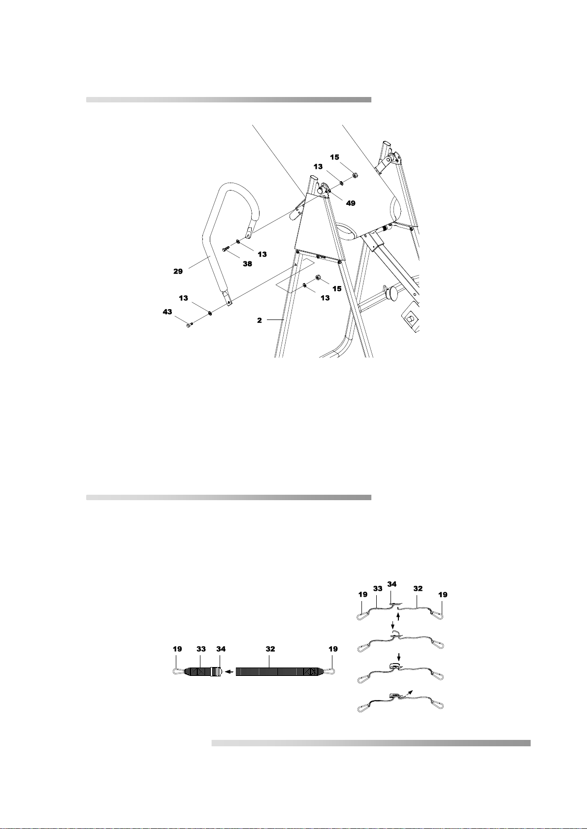
Fastening the grips
Fasten the upper end of the bar grip (29) on the rear U-frame (2) and the pivot arm reinforcement
plates (49) using a hex-head screw (38), a counternut (15) and two washers (13).
Fasten the lower end of the bar grip (29) on the rear U-frame (2) using a hex-head screw (43), a
counternut (15) and two washers (13).
Repeat this procedure for the other bar grip.
Step 8
Fasten the nylon strap to the strap buckle (34) by pulling the end of the strap through the
underside of the strap buckle, over the pre-mounted strap (33) to form a loop and down
through the strap buckle. Now slide the strap back over itself to form a loop, through the
strap buckle and tighten.

AG 02 V4 36 / 80
Seite / Page 36
Step 9
Fasten the nylon strap (32 + 33) you have just fitted to the inversion table. Do this by
hooking the safety karabiner hooks (19) located on the nylon strap into the eyelets on the
table frame and on the cross strut of the front U-frame (1).

AG 02 V4 37 / 80
Seite / Page 37
Operation and settings
1. Shorten 2. Lengthen
The strap
In the interests of safety, a nylon strap for controlling and limiting the inversion gradient is
enclosed. This strap can be set to various lengths, which allows a greater or lesser inversion
gradient.
1. To shorten the strap, thread the lower end into the strap buckle and pull at the upper
end.
2. To lengthen the strap (32), thread it into the upper end of the strap buckle and pull at the
lower end.
Adjusting the arm
The adjustable arm (3) can be individually set to several positions depending on the user's
body length. Loosen the knob (30) and pull out the spring button (18) until you can move the
arm up or down. Set the desired length, release the spring button and slide the arm up or
down slightly until it "springs" into the set position. Now retighten the knob (30).
TIP: Because different individuals have different centres of gravity, the scale provides a
setting recommendation in the first instance. Before training for the first time, set the
scale to a minimum of 5 cm below your known body height and feel, by approaching
gradually, for the position that is ideal for you.
AG 02 V4 38 / 80
Seite / Page 38
Pivot arm with mounting openings
The pivot arms are fitted with several mounting openings. These openings are used to set
the inversion gradient. To alter the setting, simply tilt the pivot arm upwards until the pin
comes out of its opening. Now slide the pivot arm into the position you want next and push
the opening back over the pin.
The lowermost opening offers the smallest inversion gradient.
The uppermost opening offers the highest inversion gradient.
We recommend that novices start with the lowest (the last or 3rd opening after the square
pin) opening so that they can become accustomed to the device.
The openings on the two pivot arms have to be engaged at the same height.
Engaging at different heights can damage the device and cause injury.
The grips
To increase comfort and safety, the inversion table has been fitted with hand grips. These
grips are located at the upper end of the rear U-frame (2). They help you return to the upright
starting position, whatever the inversion gradient. If you want to return to the upright position
and the table is moving too slowly or not at all, simply take hold of the grips and pull on them
until you are back in the starting position.
The neutral centre of gravity differs from individual to individual. The body height
shown on the scale may therefore differ from the setting that is ideal for you. Before
training for the first time, set the scale to a minimum of 5 cm below your known body
height and feel, by approaching gradually, for the position that is ideal for you. The
correct length setting has been reached if the table returns to the starting position as
soon as you move your arm down below your waist.
AG 02 V4 39 / 80
Seite / Page 39
General precautions
1. Make sure that the bolt on the pivot arm sits properly in the notch of the base frame. It
must be located at the very bottom of the notch.
2. A second person should be present when using the device for the first few times.
3. The adjustable arm should be correctly set to your height.
4. Make sure that the adjustable arm is securely held by both the large spring buttons and
by the knob (30).
5. Ensure that there is enough clearance for the table to fully rotate.
6. Ensure that the device is standing on an even, slip-free surface.
7. Make sure that the heel retainers hold your feet secure and tight and that the spring bolt
is correctly engaged. If necessary, gently slide the retainer into the next opening. Avoid
excess pressure on your feet.
Using the inversion table
1. Pull the small spring button (17) upwards and slide the adjustable instep frame (6) until
the spring button engages into the last position (opening).
2. Slide your ankles between the rubber heel holders (31) and place your feet on the foot
bar attached to the end of the adjustable arm.
3. Pull the small spring button upwards until it releases and slide the heel retainers down
until they are tight against your feet (ankles) and the spring button audibly engages
(springs).
4. Straighten up completely, lay your back against the table and hold your hands to the side
or place them in your lap.

AG 02 V4 40 / 80
Seite / Page 40
Recommendations for use
1. Start slowly: Start with an inversion of just 15° to 20°. Remain in this position for as long
as you feel OK. Slowly return to the starting position.
2. Progress slowly: Increase the angle only when you feel comfortable doing so. Increase
the angle by just a few degrees each time. Increase the duration of use by 1-2 minutes
over several weeks until you reach 10 minutes. You should only add stretching and
simple gymnastic movements when the inversion table feels comfortable.
3. Listen to your body: Slowly return to the starting position. A feeling of dizziness means
you moved too quickly. Do not use the device straight after a meal. Do not ignore a
feeling of unease. As soon as you feel unwell, return to the starting position.
4. Keep moving: Movement while inverted activates blood, lymph and fluid circulation and
supports the orientation of bones and organs. Move in traction or carry out light
gymnastic movements. Try slight lateral inclinations and rotational movements to the
right and left. Let your arms hang loose. We do not recommend strenuous exercises
while inverted. Limit partial inversion without movement to sessions of one to two
minutes.
5. Use inversion regularly: We recommend two to three sessions per day, depending on
your condition. Try to schedule the sessions for the same time.
Other manuals for Hang Up
1
Table of contents


