SiteSage TM46 User manual

DCN: 140-02302-01 Page 1
Installation Guide
Model TM46
SiteSage Thermostat
This thermostat is compatible with most HVAC systems, including the following:
24VAC systems Note: requires both the 24R and 24C (common) wires
Standard gas/oil/electric heating systems
o 1 stage heating and cooling
o 2 stage heating and cooling
Heat Pump systems:
o 1 stage heating and cooling
o 2 stage heating and cooling
o 2nd or 3rd stage Auxiliary heating (heat strips)
Do NOT use for line voltage controls (120/240VAC)
Stop! Before removing your existing thermostat do the following:
1. Take a picture of the original wires and terminal connections
2. Label the wires with the terminal markings on the old thermostat
3. Record old thermostat terminals and the wire color connected to them below
Standard HVAC System Wiring
Terminal
Marking
Meaning Typical Wire Color
May be different!!!
Take a picture!
Record the old thermostat
wire color that was connected
to the terminal
C
24VAC Common Blue
R
24VAC Return Red
G
Fan Green
W or W1
Heat stage 1 White
Y or Y1
Cool stage 1 Yellow
W2
Heat stage 2 Orange
Y2
Cool stage 2 Black
Heat Pump HVAC System Wiring
Terminal
Marking
Meaning Typical Wire Color
May be different!!!
Take a picture!
Record the old thermostat
wire color that was connected
to the terminal
C
24VAC Common Blue
R
24VAC Return Red
G
Fan Green
W or W1
Aux Heat White
Y or Y1
Compressor stage 1 Yellow
O (or B*)
Change Over Valve Orange (brown*)
Y2
Compressor stage 2 Black
* if you have a terminal marked “B” with a brown wire attached to it, that means you have a
changeover (C/O) with heating type heat pump system. Be sure to set the change over
type in the Installer Settings menu to C/O Type: w/Heat. Otherwise leave it set to
w/Cool.
DCN: 140-02302-01 Page 2
Standard HVAC System
G Fan
W1 Heat Stage 1
Y1 Compressor Stage 1
R 24VAC Return
C 24VAC Common
Thermostat Connection
Y2 Compressor Stage 2
W2 Heat Stage 2
Optional 24R Connection for single transformer HVAC Systems
RC and RH are jumpered together on thermostat board.
Cut RC/RH jumper JP1 for separate heating & cooling transformers
Y1
G
Y2
RS2
RS2
RSC
Standard Gas/Electric HVAC System Wiring
Thermostat Setup:
Standard Gas/Electric HVAC Systems
To set the HVAC system type, go to the Thermostat Info screen
and press Setup button
1. Type. Set the HVAC System Type: set to Gas/Elec
2. Fan Type. Set the HVAC Fan Type:
Set to Gas for typical gas furnace (fan is controlled by the furnace)
Set to Elec for electric heat (fan call with heat call)
3. C/O type. Not used for standard systems. Ignore this setting.
4. 2nd Stage Heat. Enable second stage heating outputs
If you have a single stage heating system, leave this set to N
If you have a 2 stage heating system, set to Y to enable.
5. Aux Heat (HP). Not used for standard systems. Ignore this setting
6. 2nd Stage Cool. Enable second stage cooling outputs
If you have a single stage cooling system, leave this set to N.
If you have a two stage cooling system, set to Y to enable.
24
R
C
W1
24RH
W2/O
RS1
RS1
RSC
24C
Cooling 24V
Fan
Cooling stage 1
Cooling stage 2
Remote Sensor 2
Remote Sensor 2
Sensor shield
24VAC Com
24V Heating
Heating stage 1
Heating stage 2
Remote Sensor 1
Remote Sensor 1
Sensor shield
Remote Sensor 2
Indoor or Outdoor type
Remote Sensor 1
Indoor type
Shielded cable Shielded cable
Default Setup:
Gas/Elec
Gas Heat
1 Stage heating
1 Stage cooling
No setup required for
this configuration
Thermostat back

DCN: 140-02302-01 Page 3
Heat Pump HVAC System
Thermostat Connection
G Fan
W1 Aux Heat
Y1 Compressor Stage 1
R 24VAC Return
C 24VAC Common
Y2 Compressor Stage 2
O Change Over Valve
For Heat Pump systems, connect the 24R connection
to either the 24RC or 24RH
Y1
G
Y2
RS2
RS2
RSC
Heat Pump HVAC System Wiring
Thermostat Setup:
Heat Pump HVAC Systems
To set the HVAC system type, go to the Thermostat Info screen
and press Setup button.
1. Type. Set the HVAC System Type: set to Heat Pump
2. Fan Type. Automatically set for heat pump systems. Ignore this setting.
3. C/O type. Change Over (reversing) Valve Type. Heat pumps change from heating to cooling by reversing operation.
You must configure the thermostat’s changeover valve setting to work correctly with your HVAC system.
Check your system information to be sure and note the color of original thermostat wire and the terminal it was connected to.
No matter what the old stat connection was (O or B), connect the wire to the thermostats W2/O terminal.
The setting of the C/O Type will set the correct system operation.
For change over with cool systems (Orange wire, O terminal): set C/O type to w/cool (most common and default setting)
For change over with heat systems (Brown wire, B terminal): set C/O type to w/heat
4. 2nd Stage Heat. Enable second stage heating outputs
If you have a single stage heating system, leave this set to N
If you have a 2 stage heating system, set to Y to enable.
5. Aux Heat (HP). If you have auxiliary heat strips, set this to Y to enable.
6. 2nd Stage Cool. Enable second stage cooling outputs
If you have a single stage cooling system, leave this set to N.
If you have a two stage cooling system, set to Y to enable.
24
R
C
W1
2
4RH
W2/O
RS1
RS1
RSC
24C
Cooling 24V
Fan
Cooling stage 1
Cooling stage 2
Remote Sensor 2
Remote Sensor 2
Sensor shield
24VAC Com
24V Heating
Aux Heating
Change Over Valve
Remote Sensor 1
Remote Sensor 1
Sensor shield
Remote Sensor 2 Remote Sensor 1
Shielded cable Shielded cable
Thermostat back
Note! If you get heating
when you expected cooling,
change the C/O type to the
opposite setting.
DCN: 140-02302-01 Page 4
INSTALLATION SETUP
Before operating the system, the HVAC System Type must be setup in
the Installer Settings/System Settings/Mechanical Settings Menu!
Default Settings: The HVAC System Type is default set for a
Gas/Electric system with Gas Heat Fan type. If this matches the HVAC
system the thermostat is connected to, then no further setup is required.
If the HVAC system has Electric heat or is a Heat Pump system, then the
Mechanical Settings must be changed to match. Go to the Installer
Settings Menu to complete the HVAC setup.
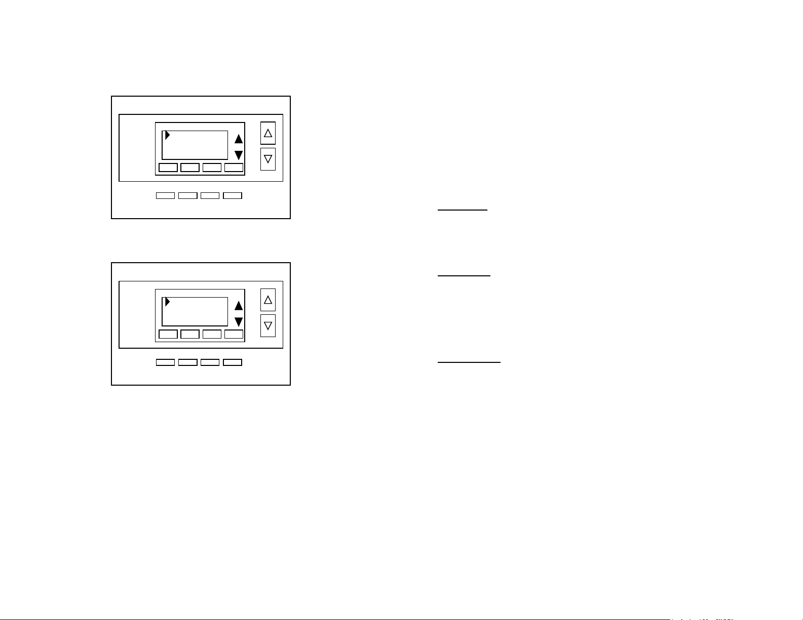
Installer Settings Menu
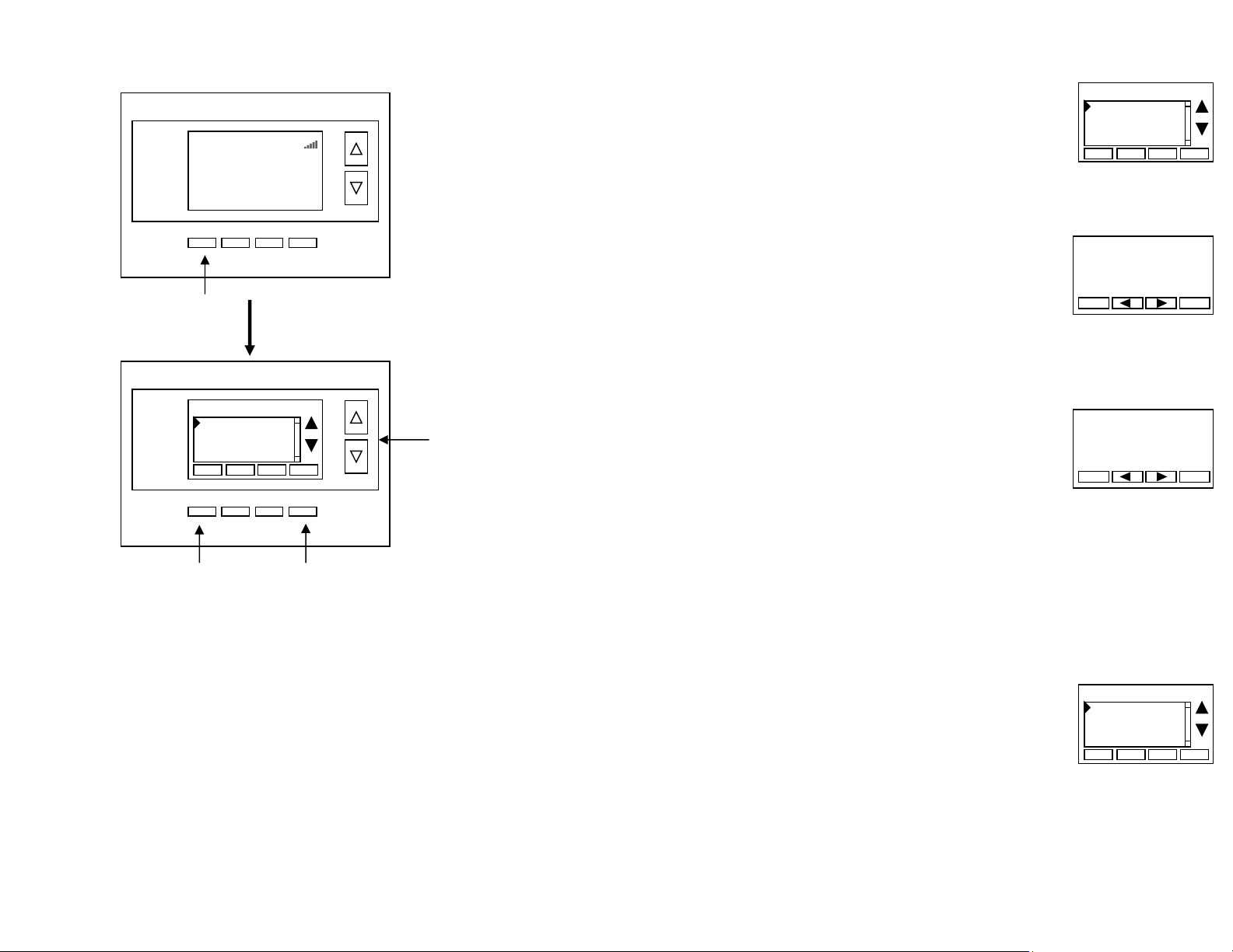
To change the HVAC setup, go to the Installer Settings Menu. This is a hidden menu
and it can be accessed by pressing the main menu button and when the main Menu
Selection screen appears, press and hold the middle two buttons for 5 seconds.
Thermostat Main Menu Selection Screen
Installer Settings Menu screen
Press and hold two middle buttons to enter the Installer Settings Menu
Done Select
Schedules
User Settings
Away Setpoints
Thermostat Info
Menu Selection
Done Select
Display Lock N
Service Mode
System Settings
Max Heat SP 90
Installer Settings
+ _
DCN: 140-02302-01 Page 5
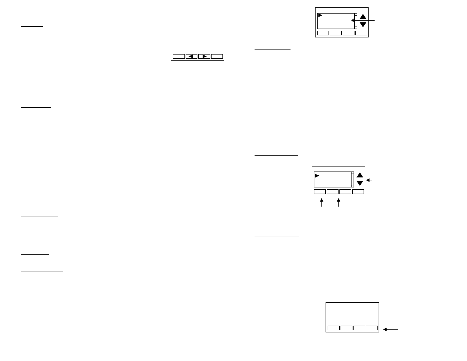
HVAC System Setup
In the Installer Settings main menu, us the down arrow button to scroll down to the System
Settings menu item and press Select.
System Settings Menu screen
Select the Mechanical Settings menu item and press Select.
Mechanical Settings Menu Screen
HVAC Setup Settings
Set these settings to match the HVAC system the thermostat is connected to.
Type Selects HVAC type, Gas/Electric or Heat pump (HP)
Options: Gas/Elec or Heat pump Default: Gas/Elec
Fan Type (if Type=Gas/Elec) Selects the heating system Fan type
Options: Gas or Electric (heat) Default: Gas
C/O Type (if Type=HP) Selects the Changeover Valve type for Heat Pump systems
Options: w/Cool or w/Heat Default: w/Cool
For retrofit installations, refer to the existing thermostat connections to help determine
correct C/O type setting. If the original system had an orange wire connected to an “O”
terminal, then it is a “changeover with cool” system. If there is a brown wire connected to
the “B” terminal, then it is a “change over with heat” system. NOTE: if you get cooling
when expect heating (or heating when you expect cooling), change the C/O type to the
other selection.
Done Select
Mechanical Settings
Sched Enable
Recovery Enable
H/C Delta
System Settings
+ _
Done Select
Type Gas/Elec
Fan Type: Gas
2nd Stage Heat N
2nd Stage Cool N
Mechanical Settings
+ _
DCN: 140-02302-01 Page 6
2nd Stage Heat Enables the 2nd Stage Heating operation
Options: Y or N Default: N
Aux Heat (if Type=HP) Enables Auxiliary Heat (heat strips) operation.
Options: Y or N Default: Y
2nd Stage Cool Enables the 2nd Stage Cooling operation
Options: Y or N Default: N
Other Installer Settings
The Installer Settings Menu includes other HVAC operation settings that can customize the
thermostat for the installation. CAUTION: these settings affect HVAC system operation
and should only be changed by qualified HVAC service technicians.
Installer Settings Menu Items
Display Lock Options: Y or N Default: N
Y = Display LOCKED N = Display UNLOCKED
Allows you to lock or unlock the thermostat buttons. When the buttons are locked, you can
still access the main menu, but you will not be allowed to select any menu options. The
Installer Settings hidden button operation is always operational, allowing you to return to
this screen and turn Display Lock off.
Service Mode
Test Mode Options: Y or N Default: N
Y= Test mode on. Reduces all delays to 10 sec for quicker system testing
N= Test mode off. Normal system delays
CAUTION: in test mode all system safety delays are shorten. Do not operate the
system compressor in test mode. Disconnect Y1 or Y2 outputs if using test mode
on a live system.
System Settings Submenu: Sets the HVAC operational settings below
Mechanical Settings Submenu: Sets HVAC system type and configuration
See HVAC setup instructions above
Schedule Enable When enabled, the local thermostat’s scheduler function is enabled.
Options: Y or N Default: N
Recovery Enable For Heat Pump Systems. Intelligent setback recovery is an automatic
advance start of heating to allow the system to be at setpoint by the schedule time without
the use of Aux Heating. Options: Y or N Default: N
H/C Delta Sets the minimum separation between heating and cooling setpoints.
Options: 3 - 15 degrees Default: 3 deg F (1 deg C)
Attempts to lower the cooling setpoint below the heating setpoint will PUSH the heating
setpoint down to maintain this separation. Same for setting the heating setpoint above the
cooling setpoint, it will PUSH the cooling setpoint up to maintain this separation.
Fan Purge Range: Fan will continue to run after a call for heating or cooling to purge the
conditioned air from the ducts.
Options: 0-120 Default: 0 (=off)
Heating Delta Stage 1 ON Sets the delta from setpoint that stage 1 heating starts.

DCN: 140-02302-01 Page 7
Options: 1 to 8 degrees Default: 1
Heating Delta Stage 1 OFF Sets the delta from setpoint that stage 1 heating stops.
Stage 1 turns off at setpoint + Delta Stage 1.
Options: 0 to 8 degrees Default: 0
Heating Delta Stage 2 ON Sets the delta from setpoint that stage 2 heating starts.
Options: 1 to 8 degrees Default: 2
Heating Delta Stage 2 OFF Sets the delta from setpoint that stage 2 heating stops.
Stage 2 turns off at setpoint + Delta Stage 2.
Options: 0 to 8 degrees Default: 0
Heating Delta Stage 3 ON Sets the delta from setpoint that stage 3 heating starts.
Option: 1 to 8 degrees Default: 3
Heating Delta Stage 3 OFF Sets the delta from setpoint that stage 3 heating stops.
Stage 3 turns off at setpoint + Delta Stage 3.
Option: 0 to 8 degrees Default: 0
Cooling Delta Stage 1 ON Sets the delta from setpoint that stage 1 cooling starts.
Options: 1 to 8 degrees Default: 1
Cooling Delta Stage 1 OFF Sets the delta from setpoint that stage 1 Cooling stops.
Stage 1 turns off at setpoint - Delta Stage 1
Options: 0 to 8 degrees Default: 0
Cooling Delta Stage 2 ON Sets the delta from setpoint that stage 2 cooling starts.
Options: 1 to 8 degrees Default: 2
Cooling Delta Stage 2 OFF Sets the delta from setpoint that stage 2 Cooling stops.
Stage 2 turns off at setpoint -Delta Stage 2.
Options: 0 to 8 degrees Default: 0
Max Heat SP Sets the maximum heating setpoint value.
Will not ramp or accept setpoints higher that this maximum.
Options: 40F to 109F (4C-43C) Default: 90F (32C)
Min Cool SP Sets the minimum cooling setpoint value.
Will not ramp or accept setpoints lower than this minimum.
Options: 44F to 113F (6C-45C) Default: 60F (15C)
Min Run Time (MRT) Sets the minimum run time before a heating/cooling cycle turns off.
Sets heating/cooling cycle time. Prevents rapid cycling.
Options: 1- 9 Minutes Default: 3
Min Off Time (MOT) Sets the minimum off time before another heating/cooling cycle can
begin. Provides compressor short cycle protection.
Options: 5-9 Minutes Default: 5
Fan Cycler
The fan cycler function cycles the HVAC system fan for an ON period followed by an Off
period continuously. Used to provide minimum air ventilation requirements. When the Fan
ON time is set to a value greater than 0, an additional “Cycler” FAN mode is present when
pressing the FAN button.
Fan ON Time Options: 0-120 minutes Default: 0 (=OFF)
Fan OFF Time Options: 10-120 minutes Default: 10
DCN: 140-02302-01 Page 8
Remote Sensors
RS1 Type Specifies the thermistor sensor temperature curve type
Options: Curve A, Type 2, Type 3 Default: Type 3
RS2 Type Specifies the thermistor sensor temperature curve type
Options: Curve A, Type 2, Type 3 Default: Type 3
RS2 Location Selects RS2 installed location as indoor sensor or outdoor sensor
Options: IN (indoor) or OUT (outdoor) Default: IN
Dehumid Options
RH Calibration Offset to add to the Humidity Sensor reading
Restore Defaults Restores all settings to factory defaults.
Options: Yes, No Default: No
Press Yes to restore defaults,
Press No to exit and not restore defaults
DCN: 140-02302-01 Page 9
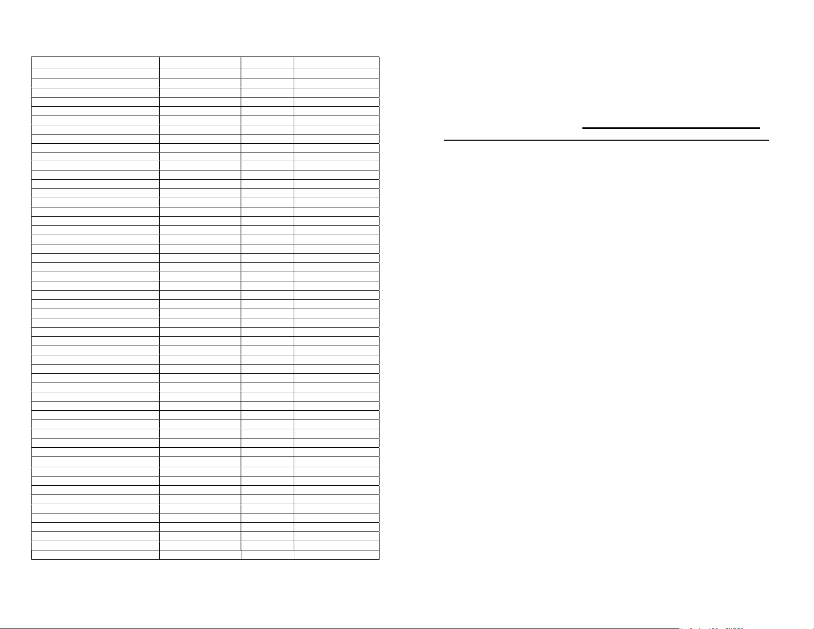
Installer Settings Summary
Setting Range Default
Display Lock Y or N N Locks out front buttons
Service Mode Submenu
Test Mode Y or N N Reduces delays for testing
System Settings Submenu
Mechanical Settings Submenu
Sys Type Std or HP Std
Fan Type Gas or Elec Gas
C/O Type w/Heat or w/Cool w/Cool
2
nd
Stage Heat Y or N N
Aux Heat Y or N Y
2
nd
Stage Cool Y or N N
H/C Delta 3 – 15 deg 3
Heat Delta Stage 1 On 1 – 8 1
Heat Delta Stage 1 Off 0 – 8 0
Heat Delta Stage 2 On 1 – 8 2
Heat Delta Stage 2 Off 0 – 8 0
Heat Delta Stage 3 On 1 – 8 3
Heat Delta Stage 3 Off 0 – 8 0
Cool Delta Stage 1 On 1 – 8 1
Cool Delta Stage 1 Off 0 – 8 0
Cool Delta Stage 2 On 1 – 8 2
Cool Delta Stage 2 Off 0 – 8 0
Max Heat SP 40-109F (4-42C) 90F
Min Cool SP 44-113F (6-45C) 60F
Min Run Time 1-9 min 3
Min Off Time 1-9 min 5
Temp Response 1-6 2
Remote Sensors Submenu
RS1 Type (curve type) Curve A, Type 2, Type 3 Type 3
RS2 Type (curve type) Curve A, Type 2, Type 3 Type 3
RS2 Location (Indoors or Outdoors) In, Out In
Restore Defaults (factory defaults) Yes or No No Exit = no
USER SETTINGS
Filter Service Submenu
Service Interval Disabled, 100-4000 hrs 300
Maint Service Submenu
Maint Interval Disabled, 100-4000 hrs 3000
Screen Timeout (to minimized screen) 0, 20-120 sec 0 0 = off , will not timeout
RH Setpoint 40-70% 50%
F/C Settings F or C F
Sensor Calibration Submenu Internal -7 to +7 0
Backlite/Display Submenu
Backlight Timeout 0, 20-120 0 0 = backlite off
Backlight On Brightness 0-100% 100%
Backlight Off Brightness 0-100% 0%
Contrast 0-20 12
DCN: 140-02302-01 Page 10
Connection to Mi-Wi Network
This thermostat is designed to connect to the SiteSage Gateway using the Mi-Wi wireless
protocol. The Gateway will automatically detect a thermostat and initiate the connection.
See the SiteSage Installation Manual for additional details.
It is critical that the MAC address of the thermostat is mapped to the
name of the zone served by the thermostat. The Thermostat MAC
address can be found in the Mi-Wi Network menu option (the last
one in the list of options shown when the Menu Button is selected.
DCN: 140-02302-01 Page 11
Operation Guide
Model TM46
SiteSage Thermostat
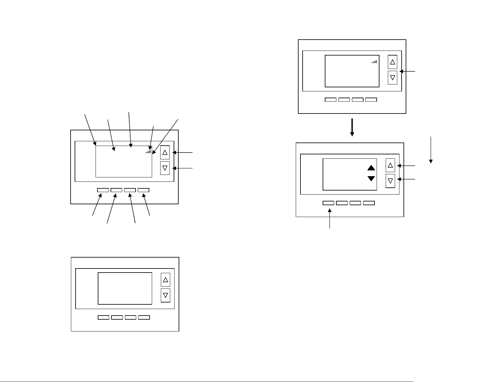
MENU
COOL
MODE
72 H
AUTO
FAN HOLD
75
2
75 C
4:30 PM
SYS
Off
Fan Off
Hold
Temperature
Setting
Warmer
Cooler
Fan Mode
Selection
Heating/Cooling
Mode Selection
Run/Hold
Mode Selection
Menu
Selection
Room
Temperatur
e
Setpoints
Backlite Display
Main Thermostat
Screen
Minimized Display
Press any button to return to the main thermostat screen
75
Thermostat Name
Zone Name
Mi-Wi Signal
Strength
DCN: 140-02302-01 Page 12
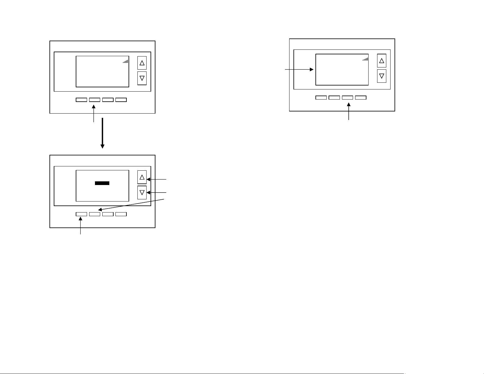
Setting the heating or cooling temperature setpoint
! If the System Mode is OFF, pressing either the Up or Down buttons will take you
to the System Mode screen. You must first set an operating mode before you can
set or change the setpoint.
! To change the Heat Setpoint you must be in the Heating mode, to change the Cool
Setpoint you must be in the Cooling mode. If you are in Auto mode, the mode of the
last system call will be the setpoint screen displayed.
Setpoint Push: Note that you cannot lower the cooling setpoint below the heating
setpoint. The thermostat will “push” the heating setpoint lower if you try to lower the
cooling setpoint below the heating setpoint. It maintains a 3 degree separation between
the heating and cooling setpoint. The same is true for raising the heating setpoint above
the cooling setpoint. Again the thermostat will “push” the cooling setpoint up to maintain
the 3 degree separation.
Lower
Temperature
Raise
Temperature
Press a button to
go to the setpoint
change screen
Setpoint change screen
Press “DONE” button to set the setpoint and exit back
to the main thermostat screen or wait for the screen to
automatically time out.
Press the up or down arrow buttons to
set the desired temperature setpoint
HEATING SETPOINT
Pressing the up
or down buttons
will increment the
setpoint 1 degree.
Press and hold
the button to
ramp the setpoint.
75
MENU
HEAT
MODE HOLD
64H
82C
AUTO
FAN
Sys Off
70
Done
Thermostat Name
DCN: 140-02302-01 Page 13
Setting the System Mode: Off, Heat, Cool, Auto
System Modes
OFF: System is off. No heating or cooling will come on. If system was on, it will turn
off immediately.
HEATING: Only heating will occur.
COOLING: Only cooling will occur.
AUTO: Heating or cooling will come on according to the heating and cooling
setpoints. The system will automatically switch between heating and cooling modes
as needed to maintain the setpoints.
Special Heat Pump Mode: Emergency Heat
EHEAT: An additional system mode, “EHEAT” for Emergency Heat will be displayed
if the HVAC system type is set to Heat Pump. If there is a compressor failure with the
Heat Pump system, setting the mode to EHEAT will allow the supplemental Aux heat
to come on first whenever there is a call for heating. It also disables the compressor
output to prevent further damage to the HVAC system.
Press the
UP or
DOWN buttons
or
MODE button
to select the
desired system
mode.
System Mode change screen
Press Mode button to
change system mode
Press “DONE” button to select the mode and exit back to the main
thermostat screen or
wait for
the
screen to automatically time out.
Done
MODE
SYSTEM MODE
OFF
HEATING
COOLING
AUTO
4:30 PM
75
MENU
HEAT
MODE HOLD
64H
82C
AUTO
FAN
Sys Off
Thermostat Name
DCN: 140-02302-01 Page 14
Setting Fan Mode and System Status Indicators
Optional Fan Mode
Fan Cycler. If the Fan Cycler feature is enabled in the Installer Setup, the additional fan
mode “Cycle” will be shown in the Fan Mode menu. This mode cycles the fan on and off
continuously for fresh air ventilation according to the settings in the Installer Setup.
System Status Indicators
When the main thermostat screen is displayed, the on-screen labels indicate the following.
System Operation mode indicator
“SYS OFF” displayed > System is OFF
“SYS MOT”1 displayed > System is OFF and Minimum Off Time (MOT) delay On is active
“HEAT ON” displayed > System is ON and heating
“COOL ON” displayed > System is ON and cooling
“HEAT MRT”2 displayed > System is ON and heating. Minimum Run Time (MRT) delay off
is active.
“COOL MRT” displayed > System is ON and cooling. Minimum Run Time (MRT) delay off
is active.
Staging display
“2nd Stg” displayed > Stage 2 heating or cooling is ON
“Aux Heat” displayed > Stage 3 heating is ON
For Heat Pump systems only: “EHEAT” > emergency heat mode active
Home/Away display
Home mode is active (current setpoints are being used)
Away setback mode is active (setback setpoints are being used)
System Alerts
Alert Text displayed > Specific alert text (Filter or Maintenance Timer)
Notes 1 and 2: See MOT and MRT descriptions on page 18
Press the Fan button to change the Fan mode
AUTO FAN: Fan automatically operated by the HVAC system.
FAN ON: Manual Fan mode. Fan stays on until mode is changed back to Auto.
System
Status
Indicators 75
MENU
HEAT
MODE HOLD
64H
82C
AUTO
FAN
Sys Off
2
n
d
Stg
Filter
4:30 PM Thermostat Name
DCN: 140-02302-01 Page 15
Menu Selection
Main Menu Items
Schedules > Optional, used to view and set programmable schedules
User Settings > set various user preferences
Away Setpoints > show and set the heating and cooling setback setpoints
Thermostat Info > displays thermostat setup info
MiWi Network Info > shows network information
Schedules is an optional menu item. It will only show up in the menu list if “Schedules”
is enabled in the Installer settings for the thermostat. Provides for local schedule control.
The Schedules Screen allows you to review and set the setback schedule for the
thermostat. The thermostat has a 4 x 7 schedule. Four times a day can be selected for
changes to the heating and cooling setpoints. Each day of the week can have a different
schedule. Groups of days can be copied with the same schedule. When the thermostat is
set to “Run” mode, the schedule will be executed daily, with the setpoints being changed
as per that days schedule stored in the thermostat. “Hold” mode stops schedule operation
and holds the current setpoints until changed manually or by network commands.
The Schedules Screen gives you the option of setting a custom setback schedule or to
load one of two preset schedules.
Press Menu button to go
to the main menu screen
Use the
UP/DOWN
buttons to select
the desired menu
item
Press SELECT to go to the
menu item screen
Press DONE to go back to
the main thermostat screen
4:30 PM
Menu Selection
Select
Schedules
User Settings
Away Setpoints
Thermostat Info
Done
75
MENU
HEAT
MODE HOLD
64H
82C
AUTO
FAN
Sys Off
Thermostat Name
DCN: 140-02302-01 Page 16
User Settings
Select
Set Clock
Filter Service
Maint Service
Screen Timeout 0
Done
Heat and Cool
Preset: Comfort
Preset: Energy Miser
Select Schedule
Select
Done
Menu Options
Heat and Cool: You can change the individual day/hour
and setpoints for the Heating and Cooling schedule by selecting
this menu item.
Preset: Comfort: This is a preset schedule with mild setbacks.
Select this menu item to load the Comfort schedule into the
thermostat. Confirmation screen will be displayed for Yes/No entry.
Preset: EnergyMiser: This is a preset schedule with deeper setbacks.
Select this menu item to load the EnergyMiser schedule into the thermostat.
Confirmation screen will be displayed for Yes/No entry.
Day Schedule Screen
When you select the Heat and Cool Schedule menu item,
the “day” schedule programming screen opens and the
schedule for current day will be displayed. Use the scroll buttons
to highlight the data to be modified. Once the data has been
highlighted, use the +/- buttons to change the value of the data.
To copy a days schedule to another day or group of days, move the cursor to “C” on the
bottom right of the schedule screen. When you highlight the “c”, the button below will
become “Copy”. Press this button to change to the Copy Schedule Screen.
Copy Schedule Screen
The Copy Schedule screen is a sub screen of the Schedule screen.
The Copy Schedule screen allows you to copy a day’s schedule
to another day or group of days.
First select the day to be copied in the Schedule screen.
Scroll to the “c” at the bottom of the Schedule screen to highlight it.
The “Next” button will change to the “Copy” button.
Press the “Copy” button to open the Copy Schedule screen.
Scroll through the days and select the days you want to copy the schedule to by setting the
“N” under each day to “Y” by using the Yes/No buttons.
After selecting all the days desired, press the “COPY” button.
Exit the Copy Schedule screen with the “DONE” button.
User Settings Menu Items
Set Clock > go to the clock setting screen
Filter Service > go to the filter timer setup screen
Maint Service > go to the maintenance timer setup screen
Screen Timeout > sets the time in seconds to switch to the
minimized screen
RH Setpoint > Setpoint for RH control
F/C Settings > go to the F/C mode selection screen
Sensor Calibration > go to the sensor calibration screen
Backlight/Display > go to the backlight and display setup screen
BACK COPY
Copy Monday Schedule
To
Tue Wed Thu Fri Sat Sun
N N N N N N
Yes
No
DONE NEXT
Monday Schedule
Time Heat Cool
Wake 06:00 A 70 79
Day 08:00 A 62 85
Eve 04:00 P 70 78
Sleep 10:00 P 62 82 C
+
-
DCN: 140-02302-01 Page 17
Set Clock: The Set Clock screen allows you to set the Thermostat’s internal clock.
To set the Time and Date, move the cursor with the navigation
arrows until the data you want to change is highlighted.
Using the + and – buttons to increment or decrement
the data to the desired setting.
When finished, press the SET button to return to the Main Menu screen or wait for screen
to timeout.
! If the clock has been reset by an extended power outage, the Clock display on the
thermostat screen will be blinking. Pressing the MENU button will take you
directly to this screen to set the clock.
Filter Service: Go to the Filter Service Screen. Sets/resets the filter timer/alert.
Shows filter runtime in hours and the service interval alert in hours (typically 300 hrs)
Change the service interval with the +/- buttons.
Reset the service alert after you have changed the filter.
Maint Service: Go to the Maintenance Service Screen. Sets/resets the maintenance
timer/alert.
The Maintenance Service screen will show the accumulated Heat and Cool runtime hours
as well as the Service Interval that will be used to trigger a Maintenance alert.
Service interval is 3000 hours. Use the +/- buttons to adjust service interval.
Press reset to clear the service alert and reset the runtimes to zero.
When the combined HEAT and COOL Runtime hours equals the Service Interval hours, a
“Maint” message will be displayed as a reminder that the HVAC system may require
periodic maintenance. Pressing the Menu button will take you to the Filter Service screen.
The Reset button can be pressed and the HEAT and COOL Runtime values will be reset to
zero.
Screen Timeout: Minimized Screen. Set the display timeout time in seconds. Options
are 0 or 15 to 120 (default set to 0 seconds). This is the time before the main thermostat
screen reverts to the minimized temperature only display screen, after the last button
press. The Minimized Screen feature is disabled by setting this time to “0”.
! Any button press will restore the main thermostat screen display.
F/C Settings: Go to the F/C Settings Screen. Select which temperature display mode
you desire, Fahrenheit (F) or Celsius (C).
Sensor Calibration: Go to the Sensor Calibration Screen. This screen allows you to
adjust the calibration of the internal and external sensors. You can change the
temperature calibration by +/- 7 degrees using the + and – buttons
When the Sensor Calibration screen is selected it will show the current temperature being
displayed on screen and the current number of degrees of offset being applied (typically 0).
If the sensor’s actual temp is (75) with 0 degrees of offset and you want it to display 76,
then press “+” to add 1 deg and it will indicate (76) in the display with 1 deg offset.
! You can refresh the info on this screen by pressing the right hand (blank) button.
When you close this screen, it may take a few seconds for the temperature displayed on
the main thermostat screen to update to the new temperature selected.
Back Set
Set Clock
Time 08:00 AM
Date 01/01/11
Day Mon
+
-
DCN: 140-02302-01 Page 18
Backlite/Display: Go to the Backlite/Display settings screen. This menu allows you to set
the backlight timeout period and adjust the display contrast.
Backlite Timeout: Sets the time from last button press that the backlite will timeout and
turn off. The timeout value is adjustable from 0 or 20 to 120 seconds. If set to “0”, the
Backlite will always be ON. If set in the range of 20 to 120 seconds, the Backlite will turn
OFF after the selected time expires.
ON Level: Sets the backlight brightness when it is on. Adjustable from 0 to 100% in 5%
steps. Screen will change brightness as you adjust setting.
OFF Level: Sets the backlight brightness when it is off. Adjustable from 0 to 100% in 5%
steps. Can be 0% = off or a low level for night viewing.
Contrast: Sets the contrast level of the LCD display, adjustable from 0 to 20. Use this
control to adjust the sharpness of the display. To light and the display looks faded, too
dark and dark lines will appear in the display. Typically 10-15 is a good setting. Adjust as
needed.
Away Setpoints
Away setpoints are used when the thermostat is set to the setback or away mode.
Thermostat Info
The Thermostat Info screen displays the current configuration of the thermostat. This
information is useful for quick check of firmware versions and HVAC system setup.
Thermostat information displayed is:
Thermostat - Model and firmware version number.
System Type - Standard or Heat Pump HVAC system
Fan Type – if HVAC type = Standard: Gas or Elect
OR
Changeover – if HVAC type = Heat Pump: Changeover with cool or changeover
with heat.
Thermostat Info Screen
Use up/down buttons to select
setpoint to change
Use +/- buttons to increase or
decrease the temperature
Press DONE to store the
setting and exit back to the
main menu
Press and Hold Setup button
to go to the HVAC system
setup screen
Done Setup
TM46 Ver 02.02.29
System Type: Standard
Fan Type: Gas
Thermostat Info
Status
Done Set
Away Setpoints
-
+
Away – Heat 65
Away – Cool 80
Temp in parenthesis (78) is the remote sensor temp.
n/a is displayed when no sensor is attached
Done
Sensor Calibration
-
+
Internal (75) 0
Remote 1 (78) 1
Remote 2 n/a 0
Outside n/a 0
DCN: 140-02302-01 Page 19
Setup Button (not labeled on screen)
To setup the thermostat to work with your HVAC system, press and hold the “Setup”
button. This will take you to the installation setup screen. See installation instructions for
proper settings.
Status Button (not labeled on screen)
Press and hold this button. A system status screen will show the output status of the
thermostat relays.
Done Button
Press Done to exit the thermostat Info screen back to the main menu.
Mi-Wi Network Info and Thermostat Name
The MiWi Network Info screen displays the current configuration of the network.
The information displayed is:
Network – will show Installed or Not Installed, indicating whether thermostat
registration at www.sitesage.net is complete.
MAC – the MAC address of the thermostat. Record this number with the zone
the thermostat serves and the heating/cooling equipment name controlled by the
thermostat.
GW MAC – the MAC address of the SiteSage Gateway the Thermostat is
connected to.
RSSI – a measure of the strength of the Mi-Wi connection to the SiteSage
Gateway; an RSSI less than 100 indicates a poor connection.
Once registered at www.sitesage.net the name given to the thermostat in the SiteSage
software appears at the top of the thermostat on the home screen.
Thermostat Operation
Minimum Run Time (MRT)
The thermostat has a Minimum Run Time after the start of any heating or cooling call.
This minimum run time assures even heating and cooling cycles. The MRT delay will keep
the system on even if reaches setpoint or you change the setpoint to a temperature that
would satisfy the call, until the MRT expires. Changing the Mode to OFF will cancel the
MRT and the system will turn off immediately. The MRT can be adjusted in the Installer
Settings menu of the thermostat.
Note: The MRT status is shown in the thermostat System Status on-screen labels.
Minimum Off Time (MOT)
The thermostat has a Minimum Off Time after any heating or cooling call is finished. This
delay prevents rapid heating/cooling cycles and also provides “short cycle protection” for
compressor calls. This delay may be noticeable when you change a setpoint and it does
not respond immediately due to another call that has recently completed and the MOT
delay timer is preventing the system from restarting. The MOT delay time can be adjusted
in the Installer Settings menu of the thermostat. There is a minimum of 5 minutes delay to
assure compressor protection.
Note: The MOT status is shown in the thermostat System Status on-screen labels.
DCN: 140-02302-01 Page 20
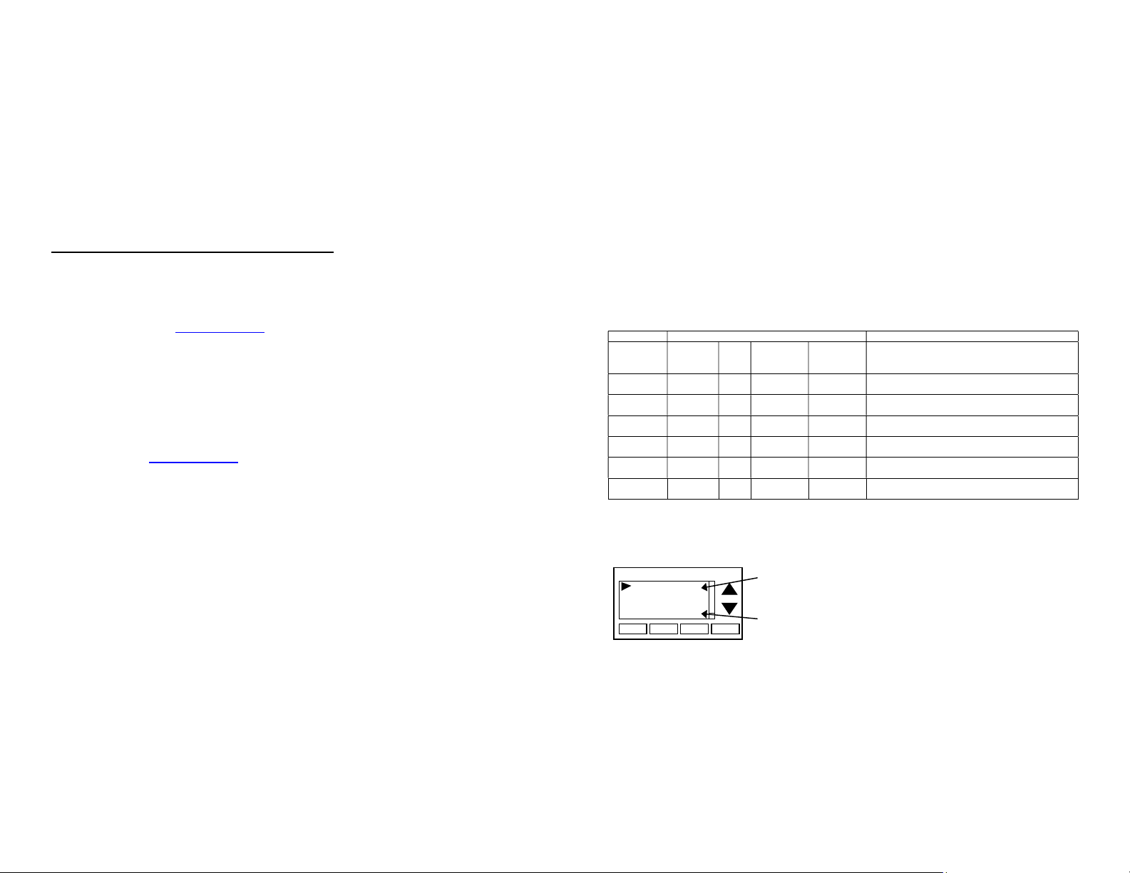
Remote Sensors
The thermostat has two remote temperature sensor inputs.
Remote Sensor RS1. When connected, the thermostat will use the RS1 remote sensor
instead of the internal sensor. Temperature displayed will be the RS1 temperature.
Remote Sensor RS2. Selectable sensor location: Inside or Outside. RS2 can be
selected to be an inside remote sensor or an outside remote sensor in the Installer
Settings/Remote Sensors menu item.
RS2 Location set to IN (Inside) (default setting). When set to Inside remote type, RS2 is
an averaging sensor that is averaged with the internal thermostat temperature sensor. If
RS1 is also attached, RS2 will be averaged with the RS1 sensor instead (since it replaces
the internal sensor).
RS2 Location set to OUT (Outside). When set to, RS2 will be used to display outside
temperature on the thermostat.
Remote sensor configurations
Sensors Used
Remote
Sensors
attached
Internal
RS1 RS2 Type
IN
RS2 Type
OUT
Sensor Function
None X Use internal sensor for room temperature
RS1 X
Use RS1 sensor for room temperature.
Internal sensor not used
RS2 X X Average internal sensor with RS2 sensor and use
the average for room temperature
RS1 and
RS2
X X Average RS1 and RS2 sensors and use the
average for room temperature
RS2
X X Internal sensor used for room temperature
RS2 sensor used for outside temperature
RS1 and
RS2
X X RS1 sensor used for room temperature
RS2 sensor used for outside temp temperature
Viewing Remote Sensor Temperatures
The actual temperatures being reported by the remote sensors can be viewed in the
Sensor Calibration Screen in the Main Menu/User Settings menu item.
Done
Sensor Calibration
-
+
Internal (75) 0
Remote 1 (78) 1
Remote 2 (n/a) 0
Outside (85) 0
Sensor temperature is displayed in the parenthesis (75). n/a is displayed when
no sensor is connected. 0 can be -7 to +7 calibration offset
If Sensor 2 location is selected as “Outside”, then sensor temp is displayed in
the Outside (85) parenthesis.

DCN: 140-02302-01 Page 21
FCC/IC
INFORMATION TO USER
This device complies with Part 15 of the FCC Rules. Operation is subject to the following
two conditions: (1) This device may not cause harmful interference, and (2) This device
must accept any interference received, including interference that may cause undesired
operation.
This equipment has been tested and found to comply with the limits for Class B Digital
Device, pursuant to Part 15 of the FCC Rules. These limits are designed to provide
reasonable protection against harmful interference in a residential installation. This
equipment generates and can radiate radio frequency energy and, if not installed and used
in accordance with the instructions, may cause harmful interference to radio
communications. However, there is no guarantee that interference will not occur in a
particular installation. If this equipment does cause harmful interference to radio or
television reception, which can be determined by turning the equipment off and on, the
user is encouraged to try to correct the interference by one or more of the following
measures.
Reorient or relocate the receiving antenna
Increase the separation between the equipment and receiver
Connect the equipment into an outlet on a circuit different from that to which the
receiver is connected
Consult the dealer or an experienced radio/TV technician for help
Any changes or modifications not expressly approved by the party responsible for
compliance could void the user’s authority to operate the equipment.
This device complies with Industry Canada licence-exempt RSS standard(s). Operation is
subject to the following two conditions: (1) this device may not cause interference, and (2)
this device must accept any interference, including interference that may cause undesired
operation of the device.
Le présent appareil est conforme aux CNR d'Industrie Canada applicables aux appareils
radio exempts de licence. L'exploitation est autorisée aux deux conditions suivantes : (1)
l'appareil ne doit pas produire de brouillage, et (2) l'utilisateur de l'appareil doit accepter
tout brouillage radioélectrique subi, même si le brouillage est susceptible d'en
Table of contents
Popular Thermostat manuals by other brands


Bryant
Bryant Preferred T6-PRH01-B installation instructions

Honeywell
Honeywell T8611G Chmnothern IV Instruciton

White Rodgers
White Rodgers 1F83-71 Installation and operation instructions

Honeywell Home
Honeywell Home T6R quick start guide

Evolve
Evolve T-100-R Operation guide

Danfoss
Danfoss RET2001RF installation guide


