11 12 13 14 15
16 17 18 19
DI-000-RT15Z-00A (65I00-4ZB) 20
For Technical Assistance Call: 800-824-3005 - www.leviton.com
LEVITON LIMITED WARRANTY
Leviton warrants to the original consumer purchaser and not for the benefit of anyone else that products
manufactured by Leviton under the Leviton brand name (“Product”) will be free from defects in material and
workmanship for the time periods indicated below, whichever is shorter: • OmniPro II and Lumina Pro:
three (3) years from installation or 42 months from manufacture date. • OmniLT, Omni IIe, and Lumina:
two (2) years from installation or 30 months from manufacture date. • Thermostats, Accessories: two
(2) years from installation or 30 months from manufacture date. • Batteries: Rechargeable batteries in
products are warranted for ninety (90) days from date of purchase. Note: Primary (non-rechargeable)
batteries shipped in products are not warranted. Products with Windows®Operating Systems: During
the warranty period, Leviton will restore corrupted operating systems to factory default at no charge,
provided that the product has been used as originally intended. Installation of non-Leviton software or
modification of the operating system voids this warranty. Leviton’s obligation under this Limited Warranty
is limited to the repair or replacement, at Leviton’s option, of Product that fails due to defect in material
or workmanship. Leviton reserves the right to replace product under this Limited Warranty with new or
remanufactured product. Leviton will not be responsible for labor costs of removal or reinstallation
of Product. The repaired or replaced product is then warranted under the terms of this Limited Warranty
for the remainder of the Limited Warranty time period or ninety (90) days, whichever is longer. This Limited
Warranty does not cover PC-based software products. Leviton is not responsible for conditions or
applications beyond Leviton’s control. Leviton is not responsible for issues related to improper
installation, including failure to follow written Installation and operation instructions, normal wear
and tear, catastrophe, fault or negligence of the user or other problems external to the Product.
To view complete warranty and instructions for returning product, please visit us at www.leviton.com.
Cat. No. – RC-1500WHZB
This product is covered by U.S. Pat. No. 8,091,795.
As per SIPCO LLC, this product may be used in a system and employs certain elements from one or
more of the following U.S. Patents: IP CO, LLC: 7,089,125; 7,054,271; 6,249,516; 6,044,062.
SIPCO LLC: 7,103,511; 6,914,893; 6,891,838; 5,714,931; 6,233,327; 7,397,907; 6,618,578; 7,079,810;
7,295,128; 7,263,073; 7,480,501; 6,437,692; 7,468,661; 7,053,767; 7,650,425; 7,739,378
FCC Compliance
This device complies with part 15 of the FCC Rules. Operation is subject to the following two conditions:
(1) This device may not cause harmful interference, and (2) this device must accept any interference
received, including interference that may cause undesired operation.
© 2014 Leviton Mfg. Co., Inc.
REMOTE SYSTEM CONNECTIONS
This thermostat has been preprogrammed with energy saving program schedules. When used with a
remote system, it is recommended that the Program Mode be configured as “None” or “Occupancy”. This
will disable the internal program schedules.
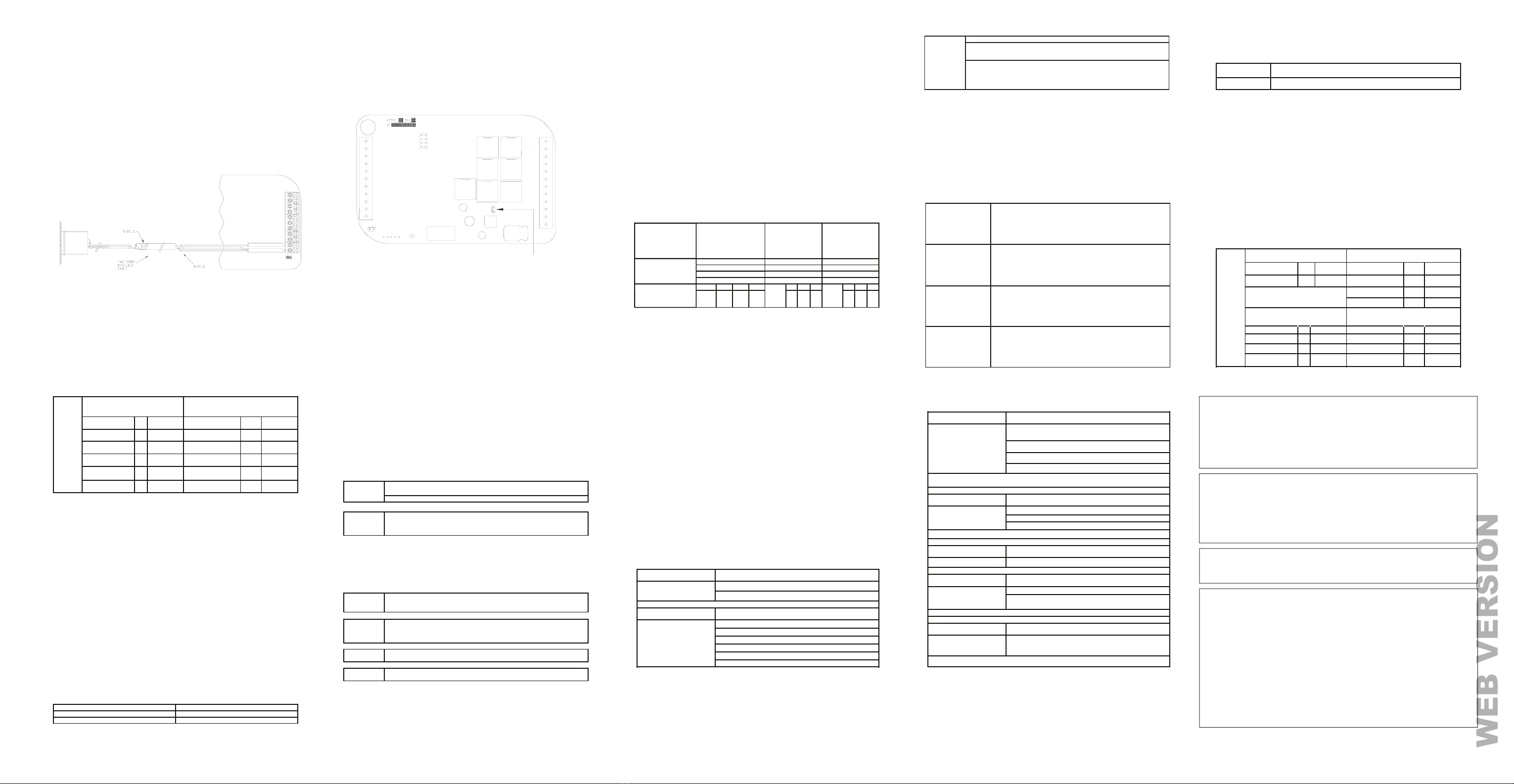
REMOTE TEMPERATURE SENSOR
A remote temperature sensor can be installed to monitor the temperature from a remote location or can be
combined with the onboard temperature sensor for the average temperature of two locations.
Run a twisted pair, shielded cable from the RC-1500 to the remote temperature sensor location. For
distances up to 100 feet, typical twisted pair, PVC-insulated, shielded cable may be used. For distances
from 100-150 feet, twisted pair with polypropylene insulated conductors, shielded must be used. For
distances from 150-250 feet, twisted pair with foam-polyethylene insulated conductors, shielded must be
used. Wire runs must not exceed 250 feet.
Make the connections to the Green and Black terminals under the section marked “Remote Temp Sensor”
on the right terminal strip - See Figure 11.
NOTES:
1. When connecting a remote temperature sensor, the shield and one of the wires from the remote
temperature sensor are tied together and get connected to the Black terminal – See Figure 11.
2. At the location of the temperature sensor, wrap the shield around the jacket of the cable and tape.
3. Configure the temperature sensor according to the application – See “Temperature Sensors” under
Installation Settings.
UP
THERMOSTAT
Black
Green
Communication
Jumper
Figure 11 – Connections to a Remote Temperature Sensor
DISABLE LOCAL CONTROL
The Task Buttons and Scroll Wheel on the thermostat can be disabled to prevent anyone from controlling
the thermostat locally.
To disable the Task Buttons and Scroll Wheel:
1. Remove the thermostat face from the thermostat base.
2. Remove the local control jumper - See Figure 12.
3. Align the tabs of the thermostat face with the slots of the thermostat base. Gently push the thermostat
face into the thermostat base locking it into place.
TO DISABLE TASK BUTTONS
AND SCROLL WHEEL
REMOVE JUMPER
COMM JUMPER
J8
Figure 12 – Local Control Jumper
SETUP AND CONFIGURATION
NOTE: For proper operation of the features of this thermostat, the Time and Date must be set. Even when
connected to a Leviton automation controller which sets the time and day, the Date must be manually set
in the thermostat under the “Settings” menu.
INSTALLATION SETTINGS
This section describes the items that the installer must setup as part of the thermostat installation. The
Installation Settings menu is used to configure the operating parameters of the thermostat.
To access the Installation Settings mode:
1. From the Home Page, press the Scroll Wheel.
2. Turn the Scroll Wheel until “Setup” is highlighted.
3. Press the Scroll Wheel or [Select] to select “Setup”.
4. Turn the Scroll Wheel until “Installation Settings” is highlighted.
5. Press the Scroll Wheel or [Select] to select “Installation Settings”.
6. Read the warning and then press [Continue] to proceed.
7. To exit Setup mode, press [Back] several times until the Home Page is displayed.
NOTES:
1. The thermostat will automatically default to the Home Page after 3 minutes of no key activity.
2. The word “default” indicates the initial setting when the thermostat is delivered from the factory.
3. Unless otherwise noted, an asterisk (*) next to a setup item indicates the default setting.
SYSTEM OPTIONS
NOTE: Before operating the thermostat, the “System Type” and “System Mode” must be configured.
The thermostat can be configured with the following system options:
System Type
*Conventional
----------------------------------
Zone Control
Dual Fuel Heat Pump1
---------------------------
Geothermal Dual Fuel
Heat Pump1
Heat Pump
-----------------------
Geothermal
Heat Pump
System Mode
*Auto Chan
eover Auto Chan
eover Auto Chan
eover
Manual Chan
eover Manual Chan
eover Manual Chan
eover
Heat Only
Cool Only
Fan On with Heat Stage
*None 1 2 3 *1, 2,
and
3
1 2 3 *1, 2,
and
3
1 2 3
1
and
2
1
and
3
2
and
3
1, 2,
and
3
1
and
2
1
and
3
2
and
3
1
and
2
1
and
3
2
3
1When configured, an additional Installer Setup menu item (Balance Setpoints) is added to the list.
PROGRAM OPTIONS
This thermostat has been preprogrammed with energy saving program schedules. When used with a
remote system, it is recommended that the Program Mode be configured as “None” or “Occupancy”. This
will disable the internal program schedules.
The program options setting sets the method for scheduling temperature change commands.
CALIBRATION OFFSET
This item is used to raise or lower the current temperature reading from the onboard temperature sensor
by .5° Fahrenheit or .25° Celsius. The default setting is 0.00.
COOL/HEAT LIMIT
These items are used to limit the desired temperature settings in cool and heat mode. The desired cool
setting can never be set below the “Cool Setpoint Min” setting and the desired heat setting can never be
set above the “Heat Setpoint Max” setting. The default setting for cool is 48°F. The default setting for heat
is 88°F.
COOL/HEAT MIN ON/OFF
These items are used to limit the on and off times of the cooling and heating system (in minutes).
Cool Minimum On
The number of minutes the
thermostat forces the cooling
system to remain on before
turning off.
Raising this number will increase the total time the cooling system is
on (saving energy), but may allow the temperature to drift farther from
setpoint (decreasing comfort). When combined with Cool Minimum
Off, cycles per hours can be obtained by using the following
calculation:
60 / (Cool Minimum On + Cool Minimum Off). The default time is 7
minutes.
Cool Minimum Off
The number of minutes the
thermostat forces the cooling
system to remain off before
starting again.
Raising this number will increase the total time that the cooling
system is off (saving energy), but may allow the temperature to drift
farther from the setpoint (decreasing comfort). When combined with
Cool Minimum On, cycles per hours can be obtained by using the
following calculation:
60 / (Cool Minimum On + Cool Minimum Off). The default time is 8
minutes.
Heat Minimum On
The number of minutes the
thermostat forces the heat to
remain on before turning off.
Raising this number will increase the total time the heating system is
on (saving energy), but may allow the temperature to drift farther from
the setpoint (decreasing comfort). When combined with Heat
Minimum Off, cycles per hours can be obtained by using the following
calculation:
60 / (Heat Minimum On + Heat Minimum off). The default time is 7
minutes.
Heat Minimum Off
The number of minutes the
thermostat forces the heat to
remain off before starting again.
Raising this number will increase the total time that the heating
system is off (saving energy), but may allow the temperature to drift
farther from the setpoint (decreasing comfort). When combined with
Heat Minimum On, cycles per hours can be obtained by using the
following calculation:
60 / (Heat Minimum On + Heat Minimum off). The default time is 8
None: The internal program schedule is disabled. Use this when connected to a remote
system for temperature change commands.
Occupancy: Program setpoints are based on the occupancy status of a remote system.
Status options are Day, Night, Away, and Vacation. This mode is also used with a remote
setback switch. NOTE: A remote system or switch is required.
*Schedule: Program setpoints are based on the time of day and day of the week.
Program
Mode
EEC
Settings
Conventional (1 Cool / 1 Heat)
Zone Control (1 Cool / 1 Heat) Conventional (2 Cool / 2 Heat)
Heat EEC *5
0 -10Heat EEC *5 0 - 10
Cool EEC *50-10 EEC *5 0 - 10
2nd Stage Differential
*2 1 -
10
Start Delay (Minutes)
*10 0
-
4hr:15min
Heat Pump and Dual Fuel Heat
Pump (1 Cool / 2 Heat)
Geothermal Heat Pumpand Geothermal
Dual Fuel Heat Pump (1 Cool /2 Heat)
Heat EEC *5 0-10 Heat EEC *5 0 - 10
Cool EEC *5 0 -
10 Cool EEC *5 0 -
10
Aux Heat Differential
*2 1 -
10 Aux Heat Differential
*2 1 -
10
Start Delay(Minutes)
*5 0 -
4hr:15min
Start Delay
(Minutes)
*45
0
-
4hr:15min
Heat Pumpand Dual Fuel Heat Pump
(2 Cool / 3 Heat)
Geothermal
Heat Pump and Geothermal
Dual Fuel Heat Pump (2Cool / 3 Heat)
Heat EEC *5 0 - 10 Heat EEC *5 0 -
10
Cool EEC *5 0 -
10 Cool EEC *5 0 - 10
2nd Stage Differential
*1 1 -
10 2nd Stage Differential
*1 1 -
10
Start Delay (Minutes)
*5 0
-4hr:15min Start Delay (Minutes)
*45
0
-4hr:15min
Aux Heat
Differential
*2 1 -
10
ux Heat Differential
*2 1 -
10
Start Delay (Minutes)
*10 0
-
4hr:15min Start Delay (Minutes)
*3hr 0
-4hr:15min
EEC
Settings
ANTICIPATOR CONTROL
The Anticipator Control settings are used to “anticipate” the need to turn the system on or off before the
temperature is actually at the setting. As humans, we perceive temperature as a combination of heat in
the air and heat radiated from the walls and surroundings.
The thermostat also measures a combination of air and wall temperature. When heating, the air
temperature rises faster than the wall temperature. The thermostat will turn the heat off briefly to prevent
overheating the air while the wall temperature catches up.
When cooling, the thermostat will periodically run the cooling system to circulate the air and remove
humidity when the temperature is close to, but not above the desired cool setting.
Because of the PID algorithm and auto balance routine which monitors the performance of the HVAC
system, the anticipator settings are automatic by default. However, the anticipator settings may be
adjusted if desired.
Heat Anticipator: This adjusts the tendency of the thermostat to turn the heating unit off before the
desired heat setting is reached. This is done to avoid overheating the air while the walls and furniture
catch up. A setting of 0-4 is intended for fast reacting heating systems, such as forced air. A setting
of 6-10 is intended for slow reacting heating systems, such as radiant heat. A setting of 5 is used for
automatic anticipation.
A lower setting will decrease the tendency to turn off the heating system before the desired heat setting
is reached. If the heating system response time is slower, as are most radiant heating systems, a higher
number will help maintain an even space temperature.
Cool Anticipator: This adjusts the tendency of the HVAC to run the cooling system to refresh and
dehumidify the air before the temperature rises to the desired cool settings. A setting of 0-4 is intended
for more humid climates and will increase the tendency for the cooling system to turn on to refresh and
dehumidify the air. A setting of 6-10 is intended for dry climates and will decrease the tendency to run the
cooling system below the cooling setting. A setting of 5 is used for automatic anticipation.
2nd/3rd Stage Extended On: When enabled and if any 2nd or 3rd stage turns on, it will remain on until
the heat/cool is satisfied, regardless of the settings for any stage differentials. The default setting is off.
Cool Anticipator*5
Heat Anticipator*5
nd
rd
TROUBLESHOOTING TIPS CONTINUED
SYMPTOM
ACTION TO TAKE
Thermostat Dead Check power to the thermostat
Check wiring diagrams
SYMPTOM
ACTION TO TAKE
Heat Or Cool Inoperative
1. Check for break in W or Y wire
2. Allow minimum off time to pass
3. Check system options for correct settings
4. If arrow is blinking, wait until startup delay expires
5. Mode is Off (Select Heat, Cool, or Auto)
6. Remote s
SYMPTOM
ACTION TO TAKE
Control By Remote
System Not Working
1. Check wires and connections to the section marked
“REMOTE SYSTEM WIRING DIAGRAMS”
2.
Check thermostat address setting
3.
Check communications mode setting
4.
Check setup of the remote system
Ensure that all setup items for the thermostat and the remote system are set to the
proper configurations for communication
SYMPTOM
ACTION TO TAKE
Temperature Reading
Incorrect
1. Allow 30 minutes for thermostat to adjust.
2. Ad
ust calibration offset
3. Change setup option to display ºF or ºC
After installation, allow the thermostat up to 30 minutes for an accurate temperature
readin
SYMPTOM
ACTION TO TAKE
Display Problem 1. Cycle power to the thermostat (R).
SYMPTOM
ACTION TO TAKE
Aux Heat On Too Often
1. Heat Pump is not able to meet load due to cold weather
2. Thermostat is in EM Heat mode – Set thermostat to Heat or
Auto mode
In EM Heat mode, onl
the auxiliar
heat is turned on
SYMPTOM
ACTION TO TAKE
Heat Pump Heats In
Cool Mode & Cools In
Heat Mode
1. Reversing valve is connected to wrong terminal - move
wire from B to O or from O to B
The wires connecting the reversing valve may be reversed
TEMPERATURE SENSORS
The Temperature Sensor settings are used to configure the internal temperature sensor and optional
remote temperature sensors that are connected to the thermostat. Any temperature sensors that are set
as the same type (i.e. indoor or outdoor) will display the average temperature reading among the sensors.
Internal Sensor: This will enable or disable the onboard temperature sensor for indoor use only.
*Enabled
External Sensor 1: This will enable the external temperature sensor for indoor or outdoor use. All indoor
and outdoor temperatures are averaged between all sensors of the same type. *Disabled
ENERGY OPTIONS
The Energy Options are used to set the fan cycle option and to configure how setbacks are changed.
ZIGBEE NETWORK
The ZigBee Network menu is to find new load control devices and devices with metering capabilities on
the ZigBee Network and to clear currently configured load control devices or metering devices from the
thermostat.
ZIGBEE SETUP
Each RC-1500 thermostat must be individually enrolled. To start the enrollment process on an RC-1500:
1. Press the “Enroll” button. The enrollment process will begin. “Finding Network” will be displayed.
2. To view the Join Details, press the “Details” button.
Find
Loads
When new load control devices are added to the ZigBee network, select “Find
Loads”. The thermostat will search for new load control devices. Any load control
devices that are found will be displayed on the Loads menu.
Find
Meters
When new devices with metering capabilities are added to the ZigBee network,
select “Find Meters ”. The thermostat will search for new metering devices.
The
data from any metering devices that are found will be displayed on the Energy View
screen .
Clear
Loads
Clear Loads is used to clear currently configured load control devices from the
thermostat.
Clear
Clear Meters is used to clear currently configured metering devices from the
thermostat.
*On: Allow the fan to come on to circulate the air during the restricted portion of the
cycle. The fan will only come on when the thermostat is in cool mode.
Off:The fan remains off durin
the restricted portion of the c
cle.
*TOU: Setbacks and Cycles are changed by TOU settings.
Fan on
during cycle
off time
Setbacks
and Cycles
change by
INSTALLER LOCKOUT
When this option is set to [Yes], the “Installation Settings” menu option is removed from the “Setup” menu
to prevent access to these settings. To access the “Installation Settings” menu, from “Setup” menu,
simultaneously press Task Buttons 1 (left), 2 (center), and the Scroll Wheel; “Installation Settings” will
appear.
Balance Setpoints (Dual Fuel Heat Pump)
The Balance Setpoints are used to determine when the auxiliary heat is used in a dual fuel heat pump
system.
•
If the outdoor temperature is above the “Upper Balance Setpoint” (45°F by default), the heat pump is
used exclusively.
•
If the outdoor temperature falls below the “Upper Balance Setpoint” but is above the “Lower Balance
Setpoint” (35°F by default) and if the heat pump is unable to heat at a rate of 5°s per hour or better, the
heat pump will turn off and the auxiliary heat will be used until the temperature rises above the “Upper
Balance Setpoint” or the call for heat has been satisfied.
•
If the outdoor temperature falls below the “Lower Balance Setpoint”, the heat pump will turn off and the
auxiliary heat will be used until the call for heat has been satisfied.
FACTORY RESET
This option will restore all system settings and programming to factory fresh configuration. Read the
warning and then press [Yes] to proceed or [Cancel] to return to Installation Settings.
STAGE SETTINGS
NOTE: Before operating the thermostat, the “Cool Stages” and “Heat Stages” must be configured.
The thermostat can be configured with the following stage settings:
EEC CONTROL
The EEC Settings are used to configure Energy Efficient Control, 2nd Stage Differential, and Auxiliary Heat
Differential. Not all of these features apply to all thermostat configurations. Only the features that apply to the
current configuration of System Type and Stage Settings will be available when this menu is selected.
This thermostat is equipped with Energy Efficient Control (EEC) that continually monitors the performance of
the HVAC system and uses Stage 2 (heat or cool) and Stage 3 (auxiliary heat) only when necessary. If the
thermostat determines that Stage 1 is able to heat or cool at a rate of 5°s per hour or better, Stage 2 will not
be used. If Stage 1 is unable to heat or cool at this rate, the thermostat will use Stage 2 as needed. Under
these conditions, Stage 1 will run continuously and Stage 2 will cycle on and off as needed. In extremely cold
conditions, the auxiliary heating will be used when Stage 1 and/or Stage 2 is not heating at a sufficient rate.
EEC: This item configures Energy Efficient Control (EEC). EEC continually monitors the performance of the
HVAC system and uses a PID algorithm and auto balance routine to achieve comfort while saving energy. A
setting of 0 will disable EEC. When EEC is disabled, the RC-1500 will attempt to maintain the temperature
within 0.5°s F of the setpoint. A lower setting of 2-3 can be used for slow reacting sources (e.g. radiant heat)
and higher setting of 7-8 for fast reacting sources (e.g. forced air). The default setting is 5.
2nd Stage Differential: This determines how far from the setpoint the temperature has to be before the second
stage turns on.
Auxiliary Heat Differential: This determines how far from the setpoint the temperature has to be before the
auxiliary heat turns on. This is only available for heat pump systems.
Start Delay (Minutes): This item sets the minimum amount of time the heating system must run before the
Auxiliary Heat Stage is used. To use this start delay, EEC must be enabled and Hold must be off.
Cool Stages The number of cool stages the HVAC system can support. The default
setting is 1.
Heat Stages The number of heat stages the HVAC system can support. Auxiliary heat
is included in this number for heat
EEC
Settings
Conventional (1 Cool / 1 Heat)
Zone Control (1 Cool / 1 Heat) Conventional (2 Cool / 2 Heat)
Heat EEC *5
0 -10Heat EEC *5 0 - 10
Cool EEC *50-10 EEC *5 0 - 10
2nd Stage Differential
*2 1 -
10
Start Delay (Minutes)
*10 0
-
4hr:15min
Heat Pump and Dual Fuel Heat
Pump (1 Cool / 2 Heat)
Geothermal Heat Pumpand Geothermal
Dual Fuel Heat Pump (1 Cool /2 Heat)
Heat EEC *5 0-10 Heat EEC *5 0 - 10
Cool EEC *5 0 -
10 Cool EEC *5 0 -
10
Aux Heat Differential
*2 1 -
10 Aux Heat Differential
*2 1 -
10
Start Delay(Minutes)
*5 0 -
4hr:15min
Start Delay
(Minutes)
*45
0
-
4hr:15min
Heat Pumpand Dual Fuel Heat Pump
(2 Cool / 3 Heat)
Geothermal
Heat Pump and Geothermal
Dual Fuel Heat Pump (2Cool / 3 Heat)
Heat EEC *5 0 - 10 Heat EEC *5 0 -
10
Cool EEC *5 0 -
10 Cool EEC *5 0 - 10
2nd Stage Differential
*1 1 -
10 2nd Stage Differential
*1 1 -
10
Start Delay (Minutes)
*5 0
-4hr:15min Start Delay (Minutes)
*45
0
-4hr:15min
Aux Heat
Differential
*2 1 -
10
ux Heat Differential
*2 1 -
10
Start Delay (Minutes)
*10 0
-
4hr:15min Start Delay (Minutes)
*3hr 0
-4hr:15min
EEC
Settings
Copyright and Trademark Information
This document and all its contents herein are subject to and protected by international copyright and
other intellectual property rights and are the property of Leviton Manufacturing Co., Inc, its subsidiaries,
affiliates and/or licensors.
Use herein of third party trademarks, service marks, trade names, brand names and/or product names
are for informational purposes only, are/may be the trademarks of their respective owners; such use is
not meant to imply affiliation, sponsorship, or endorsement.
No part of this document may be reproduced, transmitted or transcribed without the express written
permission of Leviton Manufacturing Co., Inc.
FOR CANADA ONLY
For warranty information and/or product returns, residents of Canada should contact Leviton in writing
at Leviton Manufacturing of Canada Ltd to the attention of the Quality Assurance Department,
165 Hymus Blvd, Pointe-Claire (Quebec), Canada H9R 1E9 or by telephone at 1 800 405-5320.
SYMPTOM
ACTION TO TAKE
Thermostat Dead Check power to the thermostat
Check wiring diagrams
SYMPTOM
ACTION TO TAKE
Heat Or Cool Inoperative
1. Check for break in W or Y wire
2. Allow minimum off time to pass
3. Check system options for correct settings
4. If arrow is blinking, wait until startup delay expires
5. Mode is Off (Select Heat, Cool, or Auto)
Remote s
stem is overridin
thermostat
SYMPTOM
ACTION TO TAKE
Control By Remote
System Not Working
1. Check wires and connections to the section marked
“REMOTE SYSTEM WIRING DIAGRAMS”
2.
Check thermostat address setting
3.
Check communications mode setting
4.
Check setup of the remote system
Ensure that all setup items for the thermostat and the remote system are set to the
proper configurations for communication
SYMPTOM
ACTION TO TAKE
Temperature Reading
Incorrect
1. Allow 30 minutes for thermostat to adjust.
2. Ad
ust calibration offset
3. Change setup option to display ºF or ºC
After installation, allow the thermostat up to 30 minutes for an accurate temperature
reading
SYMPTOM
ACTION TO TAKE
Display Problem 1. Cycle power to the thermostat (R).
SYMPTOM
ACTION TO TAKE
Aux Heat On Too Often
1. Heat Pump is not able to meet load due to cold weather
2. Thermostat is in EM Heat mode – Set thermostat to Heat or
Auto mode
In EM Heat mode, onl
heat is turned on
SYMPTOM
ACTION TO TAKE
Heat Pump Heats In
Cool Mode & Cools In
Heat Mode
1. Reversing valve is connected to wrong terminal - move
wire from B to O or from O to B
The wires connecting the reversing valve may be reversed
1.
2.
TROUBLESHOOTINGTIPS


