Sitex T-900 Series User manual

OPERATION MANUAL
MARINE RADAR
T-900 Series
This product is specifically
designed to be installed on boats
and other means of maritime
transport. If your country forms part
to the EU, please contact your
dealer for advice before attempting
to install elsewhere.
T-900SER.OM.E 0093142132-00-S
Digital


T-900 series Document Revision History
0093142132-00 i
T-900 series Operation Manual
Doc No. 0093142132
Document Revision History
No. Doc. No / Rev. No. Date Revised
(D/M/Y)
Revised Content
0 0093142132-00 18/07/2008 First edition
1
2
3
4
5
6
7
8
9
10
Document No. Revised Version Norm
When part of the document needs to be revised, change the cover and the version of chapter in which
the revision occurs. And, keep a version of original chapter unchanged. The document No. is indicated
at the lower right side on the cover and atthe leftor right side of the footer region of each page.
Ban of Re-use/ Transcription
Unless the re-use/transcription of a document is permitted in written form of SI-TEX manufacturing
company, we prohibit the unauthorized transcription and re-use of any part of content in this manual.
Non-liability
The specification and engineering content described in this manual may be changed without notice.
SI-TEX manufacturing company is not liable for any human damage, or damage or trouble due to
misunderstanding of content described in this manual.

Important Notices T-900 series
ii 0093142132-00
Important Notices
•The re-use and transcription of the Operation Manual (hereafter called this manual) requires
permission from SI-TEX. SI-TEX prohibits any un-authorized re-use and transcription.
•If this manual is lost or damaged, consult the dealer or SI-TEX.
•The specifications of our products and the content in the Operation Manual may be changed without
notice.
•In the explanations of this manual, the content displayed on the menu of the product may be
different. The keys and menus in the illustrations may differ in physical font and shape. And some
parts may be omitted.
•SI-TEX isnot liable or responsible for damage ortrouble due to misunderstanding of the content
described in this manual.
•SI-TEX isnotliable or responsible for damage due to “acts of nature” such asearthquake, lightning,
fire actions by third parties, other accidents, customer’s unintended error/abuse or damage caused
by use under other abnormal conditions.
•SI-TEX isnot liable for financial or loss (change/loss of memorized content, loss of business profit,
business failure) due to use or failure of our products.
•SI-TEX isnot liable for any damage due to malfunction caused by the combination of software and
connected equipment which are not specifically approved.

T-900 series For Safe Operation
0093142132-00 iii
For Safe Operation
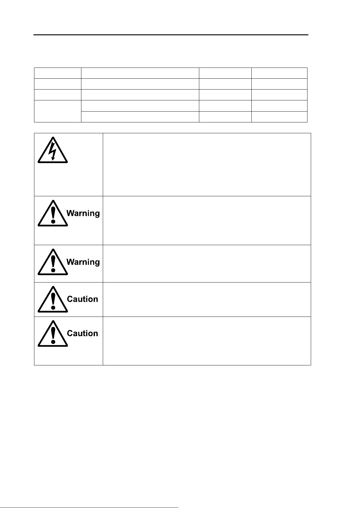
Symbol used in this Operation Manual
This Operation Manual uses the following symbols. Understand the meaning of each symbol and
implement the maintenance and inspections given.
Symbol Meaning
Warning mark
Handle correctly. Otherwise, it may lead to death or serious injury.
High Voltage Caution mark
Handle correctly. Otherwise, electrocution may occur, which could result in
death or serious injury.
Caution mark
Handle correctly. Otherwise, it may lead to light injury or damage to the
equipment.
Prohibit Mark
This mark indicates that the specific action is prohibited. The inhibited
action is displayed around the mark.
Cautions and Warnings on Equipment
Be careful of rotating aerial.
The radar may start to rate without notice. For safety, keep away from the
radar.
Be careful of high frequency interference
Strong electromagnetic wave is radiated from the antenna. If the
electromagnetic wave is continuously radiated, human bodies may be
affected. The international law defines that the electromagnetic wave of a
power density of below 100W/m2 does not affect human bodies.
However, a medical appliance such as pacer maker may become unstable
due to small amount of power of electromagnetic wave.
In any cases, a person wearing such appliance should not be allowed
access to a place where the electromagnetic wave is radiated,
For Safe Operation T-900 series
iv 0093142132-00
Distance from equipment having a specific power density of electromagnetic wave.
(By IEC 60945 regulation)
Model Transmitting power/ Antenna length 100W/m210W/m2
MDC-921 2kW/ 1.2 feet (Radome antenna) 0.4m1.27m
MDC-941 4kW/ 2 feet (Radome antenna) 0.8m2.54m
4kW/ 3 feet (Open antenna) 0.9m2.85m
MDC-940
4kW/ 4 feet (Open antenna) 1.01m3.2m
Be careful of a high voltage inside.
A lethal high voltage is used. This high voltage remains in the circuit after
you have turned off the power switch. To prevent touching the high voltage
circuit inadvertently, the protective cover is provided to the high voltage
circuit and the high voltage caution label is affixed. Be sure to turn off the
power switch for your safety and discharge the electricity remaining in the
capacitor before starting inspections. Only an engineer authorized by
SI-TEX should providesinspections and maintenance.
Be sure to turn off the power of the boat.
If the power switch is inadvertently turned on during work, lethal
electrocution could occur. To prevent such an accident from occurring, be
sure to turn off the power of the boat and the power of the equipment.
Furthermore, it is safer to hang a caution tag described as [Under Work]
near the power switch of the equipment.
Be careful of dust
Inhaling dust may cause a respiratory problem. When cleaning the inside of
the equipment, be careful not to inhale dust. Wearing a safety mask is
recommended.
Caution on location of equipment
Do not install the equipment where it is excessively damp and exposed to
water spray or dripping. The inside of the unit may be misted and the inside
may be corroded.
Preventing from static electricity
Static electricity may be generated from the carpet on the floor in the cabin
or clothes made of synthetic fiber. Static electricity can damage the
electronic parts in the circuit board. Be sure to take appropriate measures to
disseminate any static electricity from your body before handling the circuit
board.
T-900 series For Safe Operation
0093142132-00 v
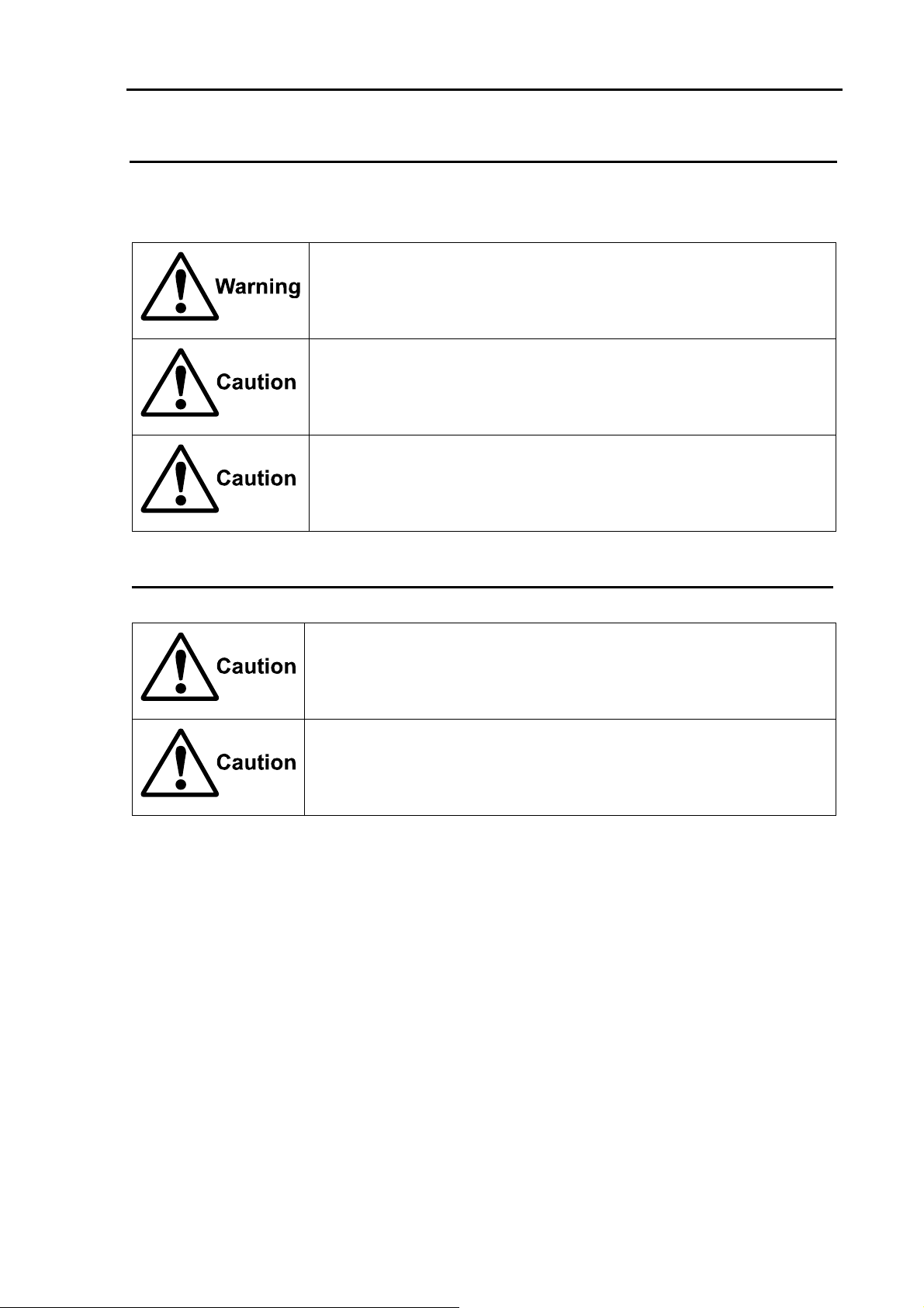
Cautions and Warnings on Handling
Do not disassemble or modify. Otherwise fire, smoking or electric shock could occur. In case of trouble,
contact your dealer or SI-TEX.
In case of smoking or fire, turn off the boat power and the power of this
unit. Otherwise, fire, electric shock or damage could occur.
The information displayed in this unit is not provided directly for your
navigation. For your navigation, be sure to see the specified material.
Use the specified fuse. If un-specified fuse is used, it may cause a fire,
smoking or damage.
Caution on Display Unit
Do not push or scrub the surface of the display unit with a pointed tip of a
hard matter (tool, tip of a pen, etc) Scars could be made.
Do not press the surface of the display unit. Interference stripes or display
abnormality could occurs.

Contents T-900 series
vi 0093142132-00
Contents
Document Revision History ...................... i
Important Notices .....................................ii
For Safe Operation..................................iii
Introduction............................................viii
System Configuration ..............................ix
Configuration of Equipment..................... x
Chapter 1 Basic Operation..................... 1-1
1.1 How to read the radar screen.....1-3
1.2 How to use the keys...................1-4
1.3 Power On/Off..............................1-6
Power On ...................................1-6
Power Off ...................................1-6
Language Selection at Initial
Start-up.......................................1-6
1.4 Brilliance Adjustment..................1-6
Brightness Adjustment of LCD ...1-6
Brightness Adjustment of
Panel ..........................................1-6
1.5 Transmission ..............................1-6
Start of Transmission..................1-6
Stop of Transmission..................1-6
1.6 Switch-over of Range.................1-7
Change of Range .......................1-7
Change of Sub-screen Range....1-7
1.7 Gain Adjustment.........................1-7
Gain Adjustment.........................1-7
Adjustment of Sub-screen
Gain............................................1-7
1.8 STC Adjustment .........................1-8
STC Adjustment .........................1-8
1.9 Use of [F1] and [F2] keys ...........1-8
How to use [F1] and [F2] keys ...1-8
1.10 Delete of Heading Line...............1-9
Delete of Heading Line...............1-9
1.11 Use of Crosshair Cursor.............1-9
1.12 Measuring the distance and
bearing between two points .....1-10
Measuring the distance and bearing
between two points ..................1-10
1.13 Camera Display........................ 1-10
How to connect a CCD
camera .....................................1-10
How to display the video of a
CCD camera ............................1-10
Chapter 2 How to use the menu.............2-1
2.1 How to operate the menu...........2-1
Display/Non-display of Menu .....2-1
Operation of Menu .....................2-1
2.2 FTC Adjustment .........................2-2
2.3 Setting of Display Mode .............2-2
H UP (Head Up) ......................... 2-2
N UP (North Up) .........................2-3
C UP (Course Up) ...................... 2-3
WPT UP .....................................2-3
Relative Motion (RM) and True
Motion (TM)................................2-3
True Motion Reset......................2-5
2.4 Display Select ............................2-5
PPI Display................................. 2-5
PPI/PPI Display..........................2-5
Note on PPI/PPI Display ............2-6
PPI/NAV Display ........................ 2-6
Note on PPI/NAV Display...........2-6
2.5 Setting of OFF CENTER............2-6
2.6 Setting of Enhance
(Enlarged Target) .......................2-6
2.7 Setting of Signal Process...........2-6
2.8 Setting of Pulse Width................2-7
2.9 Trailing........................................2-7
Relative Display (R) ...................2-7
True Display (T)..........................2-8

T-900 series Contents
0093142132-00 vii
2.10 EBL ............................................ 2-8
2.11 VRM ........................................... 2-8
2.12 Display Color.............................. 2-9
2.13 Crosshair Cursor Shape ............ 2-9
2.14 PI (Parallel Index Line) .............. 2-9
2.15 Bearing Mode............................. 2-9
2.16 Vector......................................... 2-9
2.17 Alarm........................................ 2-10
IN Mode ................................... 2-10
OUT Mode ............................... 2-10
Setting of Alarm Range............ 2-10
2.18 Sleep........................................ 2-10
Operation during executing the
sleep ........................................ 2-10
2.19 AIS ........................................... 2-10
Setting of Symbol Display of
AIS ........................................... 2-11
Setting of Detailed Information of
Designated Symbol Display..... 2-11
Types and Meanings of AIS
Symbols ................................... 2-11
2.20 ATA........................................... 2-11
Automatic Acquisition............... 2-12
Manual Acquisition................... 2-12
Target Level ............................. 2-12
Target Delete............................ 2-12
Number of Acquisition.............. 2-13
Information Display .................. 2-13
Types and Meanings of ATA
Symbols ................................... 2-13
Chapter 3 How to use the system
menu ......................................3-1
3.1 Display of System Menu ............ 3-1
3.2 Setting of Assist Items................ 3-1
3.3 Setting of Adjustment Items ....... 3-2
3.4 NMEA......................................... 3-7
3.5 Preset......................................... 3-7
3.6 Self-diagnosis ............................ 3-8
Chapter 4 Maintenance........................... 4-1
4.1 Maintenance .............................. 4-1
4.2 Fuse Replacement..................... 4-3
4.3 Consumables ............................. 4-3
4.4 Trouble Diagnosis ...................... 4-3
Chapter 5 Equipment ............................. 5-1
5.1 Antenna Installation ................... 5-1
5.2 Mutual Connection Diagram .... 5-10
5.3 Installation Display Unit............ 5-11
5.4 Adjustment after Installation..... 5-13
5.5 Wiring....................................... 5-14
5.6 List of Input/Output
Sentence.................................. 5-18
Chapter 6 Attached Table....................... 6-1
6.1 Menu Configuration.................... 6-1
6.2 Specifications ............................. 6-3
6.3 External View ............................. 6-5
Chapter 7 Principle of radar system ....... 7-1
7.1 What is the radar system? ......... 7-1
7.2 Characteristics of radar radio
wave........................................... 7-2
7.3 Radar interference ..................... 7-4

Introduction T-900 series
viii 0093142132-00
Introduction
Thank for yourpurchase of SI-TEX color LCD radarT-900 series.
The quality and endurance of a unit is well considered. For the best performance, read this Operation
Manual and operate a unit correctly and safely.
The main features of this unit are as follows.
•The high performance radar equipped with 8.4 inch display can be used for professional use.
•In the true trail function, as moving targets such as other ships are displayed being tailed and
stationary targets such as land are displayed being fixed, the moving targets and fixed targets can
be easily discriminated.
•Two screen images of different ranges can be displayed. If you set a near distance screen and a far
distance, you can navigate properly and grasp a situation.
•The automatic tracking function (ATA) is provided. The maximum 50 targets can be tracked. The
current motion of other ships can be grasped in a vector and numeral so that it helps your ship to
navigate safely. (Optional)
•By connecting the AIS receiver, the gathered information such as name, heading and speed of a
ship can be displayed. (Optional interface)
•With the adoption of a specific filter (AR coat), an image can be seen clearly, refusing sunshine. The
countermeasures against the reflection on the LCD screen and dew are provided.
•The RGB output for an external monitor is provided as standard equipment. The use of the external
monitor enables you to observe easily the radar screen at a location which is remote from a main
unit. (External monitor: Prepared by a customer)
•A video from a CCD camera can be displayed. The inside of a ship can be observed by a camera
installed at the engine room helps your ship navigate safely. (CCD camera: Prepared by a customer)
•With the adoption of the gain/STC rotary knob, the operability is enhanced.
•When flush-mounted, a unit can be installed or removed from the front of the unit.
T-900 series System Configuration
0093142132-00 ix
System Configuration
Connection Diagram
Be sure to connect the KGC-1 to J4.
: Standard product
: Optional product
: Product prepared by a user
ENT
MENU
RANGE
GAIN
TX
BRILL
10.8 31.2VDC
CCD camera
External Monitor
External Buzzer
Display Unit MRD-103
Navigation Equipment Navigation Equipment
J1
J2 J6
J3 J4
Antenna Unit
RB714A/RB715A/RB716A
Remote Display
MRD- XXX
AIS receiver
J7
J5 POWER
Configurationof Equipment T-900 series
x 0093142132-00
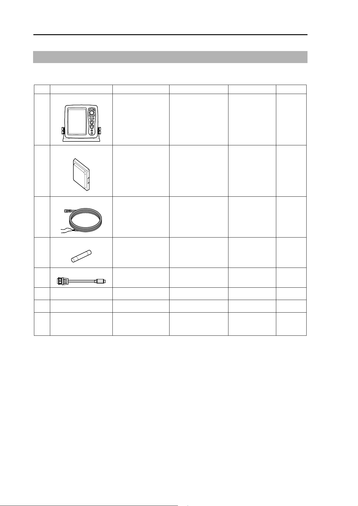
Configuration of Equipment
Standard Equipment Configuration List
No Name of item Type Remarks Weight/Length Quantity
1 Display unit
MRD-103 With mounting
bracket and knobs
3.7kg 1
2 Hard cover
E57MB11060 250g 1
3 DC power cable
CW-265-2M 2m 1
4 Fuse
F-1065-8A
Cylinder (ø6.3x32)
Normal fusion type
for main power
1
5 CCD camera cable
CW-405-0.3M 30cm 1
6 Antenna unit See next page. With cable 1
7 Operation Manual English 1
8 Quick Reference
Guide
English 1
T-900 series Configurationof Equipment
0093142132-00 xi
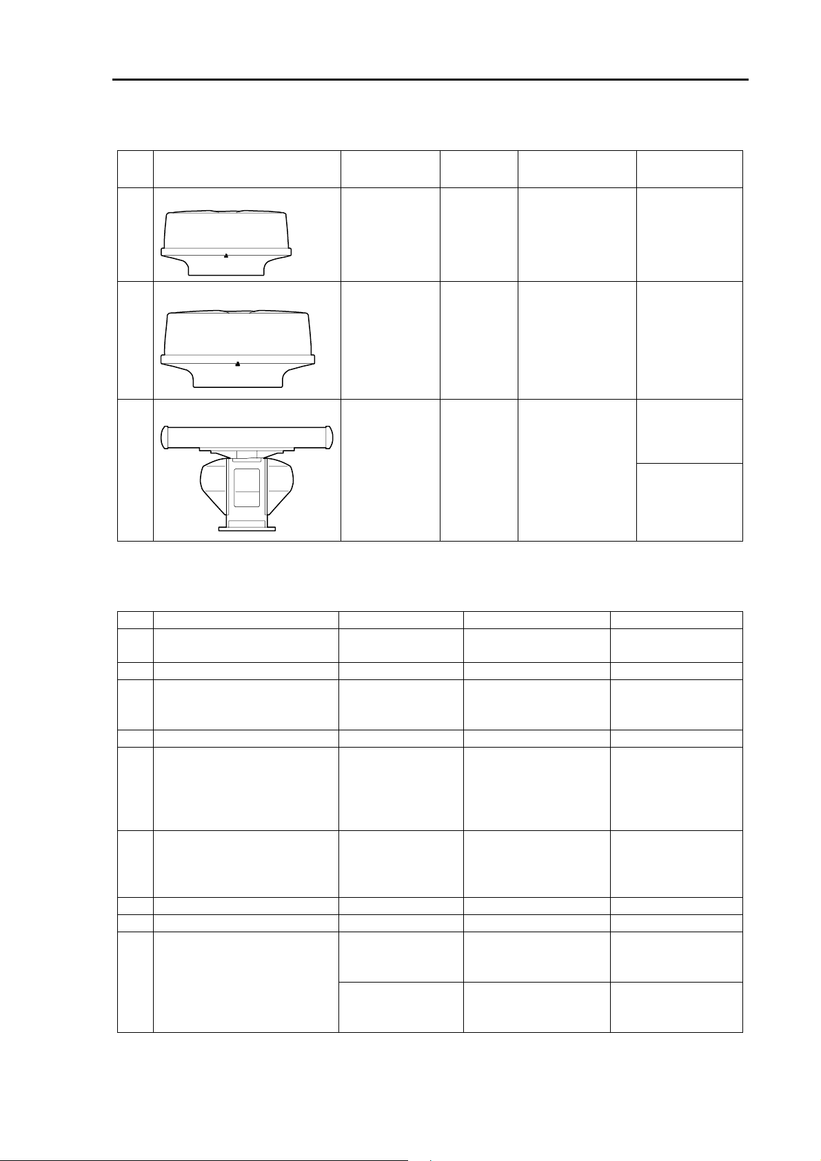
Types of Antenna unit
No Type Transmitting
Power
Shape Remarks Antenna
Weight/Length
1 RB714A
2kW Radome With 10m cable* 6kg / 1.2ft
2 RB715A
4kW Radome With 10m cable* 10kg / 2ft
21kg / 3ft3 RB716A
4kW Open With 10m cable*
22kg / 4ft
* Cables of 20m and 30m are available. (Optional)
Optional List
No Item Name Type Remarks Cable Length
1 GPS compass KGC-1 GPS/Heading
measuring
-
2 AIS interface AIS-110
3 Cable for AIS receiver CW-376-5M With 6-pin waterproof
connector and one
end plain.
5m
4 ATA interface MRE-340
5 Cables for external
monitor/external buzzer
CW-576-0.5M With 10-pin
waterproof
connector/D-sub
(female)+ buzzer
terminal
0.5m
6 Cable for remote display CW-561-10M With 12-pin
waterproof
connectors at both
ends.
10m
7 Power rectifier PS-010 With two fuses (5A)
8 AC power cable VV-2D8-3M Both ends plain.
CW-373-5M With 6-pin waterproof
connectors at both
ends.
5m9 Cable for navigation cable
CW-376-5M With 6-pin waterproof
connector and one
end plain.
5m
Chapter 1 Basic Operation T-900 series
1-1 0093142132-00
Chapter 1 Basic Operation
The basic operation of this unit is as follows. For detailed explanation, refer to each item in this manual.
1.
1.3 Power On/Off
2.
1.5 Transmission
1. Press the [BRILL] to turn
on the power.
When [ST'BY] appears, press
the [STBY/TX] key to start
the transmission.
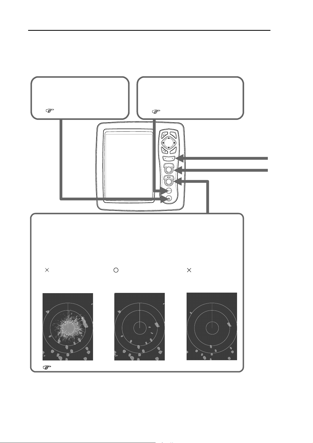
5. Rotate the [STC] knob to adjust the sea surface reflection suppression effect.
The suppression effect becomes strong when rotating clockwise the knob and
becomes weak when rotating counterclockwise the knob.
・This function reduces the gain at a near distance. If you turn clockwise the knob
too much, desired objects may disappear. Adjust properly to meet the weather
condition.
Example of STC adjustment :
: The suppression
is too weak.
: Optimum
suppression.
The reflection from sea
surface is displayed.
The desired objects
are displayed.
:Thesuppression
is too strong.
Some objects are
not displayed.
1.8 STC adjustment
ENT
MENU
RANGE
GAIN
TX
STBY
BRILL
T-900 series Chapter 1 Basic Operation
0093142132-00 1-2
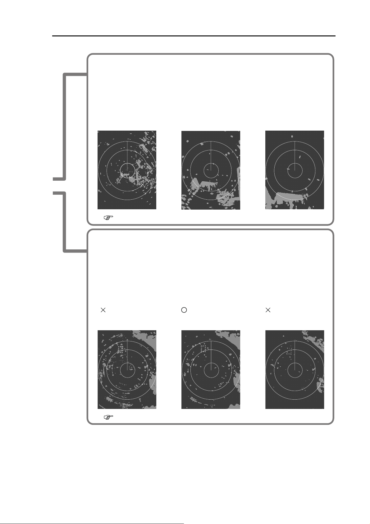
3.
Change the observation range with the [- RANGE +] key.
When pressing the [+] key, the observation range expands.
When pressing the [-] key, the enlarged surrounding around own ship can be observed.
To make it easier to observe the range you desire, change the range.
Example of display :
Long range : Far distance Middle range : Middle distance
Objects at far distance
can be covered.
Short range : Near distance
Objects near own ship
can be easily confirmed.
1.6 Switch-over of range
4.
Adjust the gain by rotating the [GAIN] knob.
Example of gain adjustment:
: Too high gain
Noise is also displayed. Desired targets are
displayed.
Some targets are not
displayed.
: Optimum gain : Too low gain
1.7 Gain adjustment
The gain becomes high when rotating clockwise the knob and becomes low when rotating
counterclockwise the knob.
When the observation range is narrow or targets are crowded, reduce the gain so that
targets can be easily seen.
When the observation range is wide, if the gain is increased, it is effective.
But, due to noise increase, small targets become hard to be seen.
Chapter 1 Basic Operation T-900 series
1-3 0093142132-00
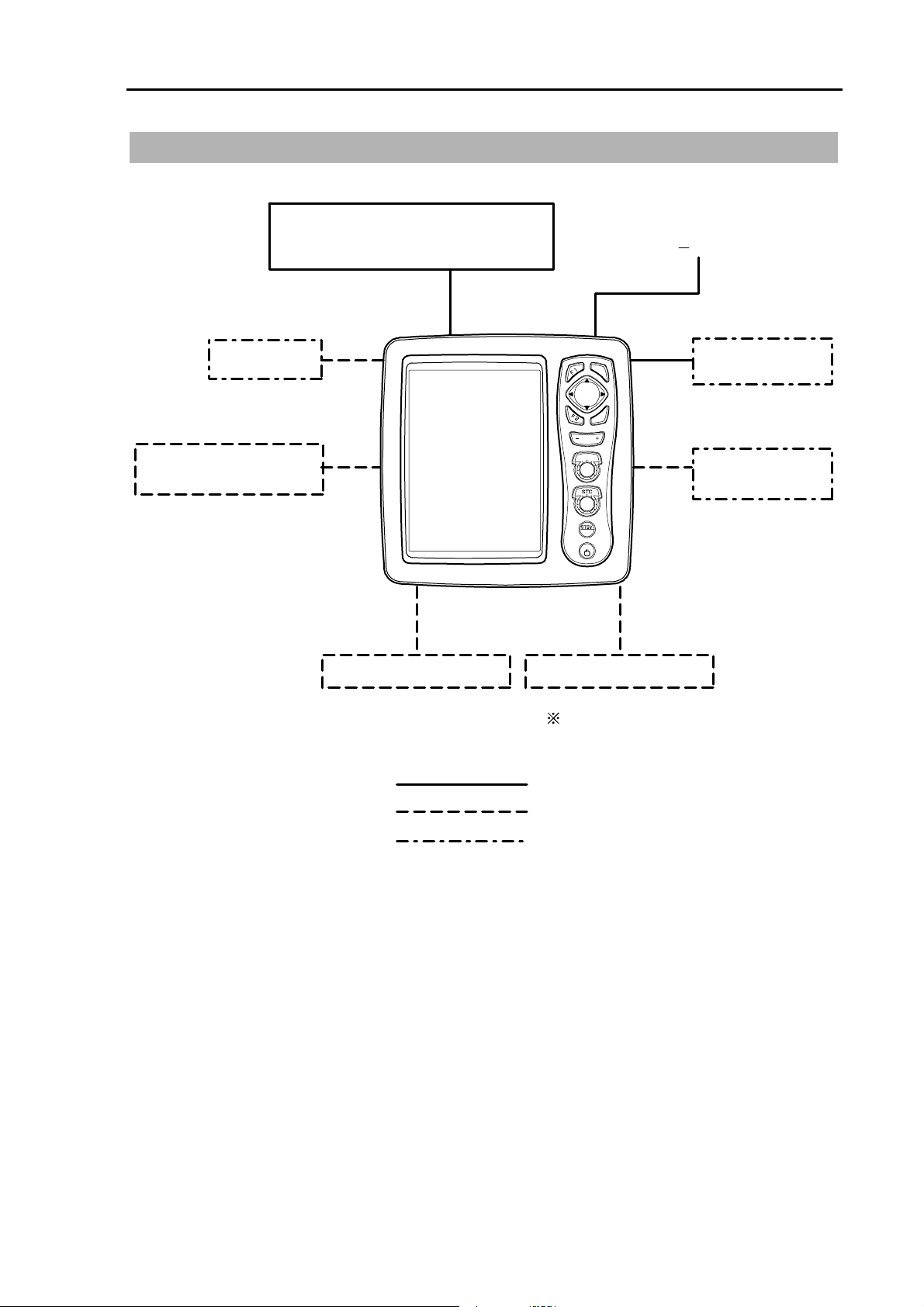
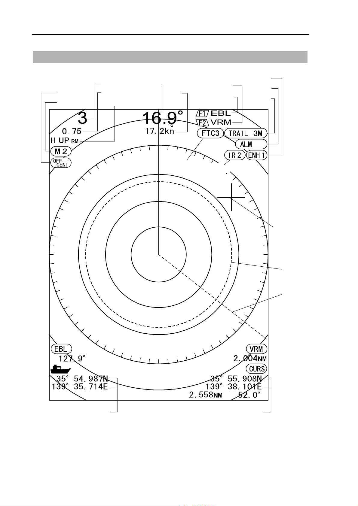
1.1 How to read the radar screen
FTC
EBL
VRM
IN
Off center
Pulse width
Range
Fixed marker interval
Display mode
Heading
Ship
speed
F2 key content
F1 key content
Enhance
Alarm
Trail
Interference
Rejection
Crosshair
cursor
Cursor position
OWN ship's position
T-900 series Chapter 1 Basic Operation
0093142132-00 1-4
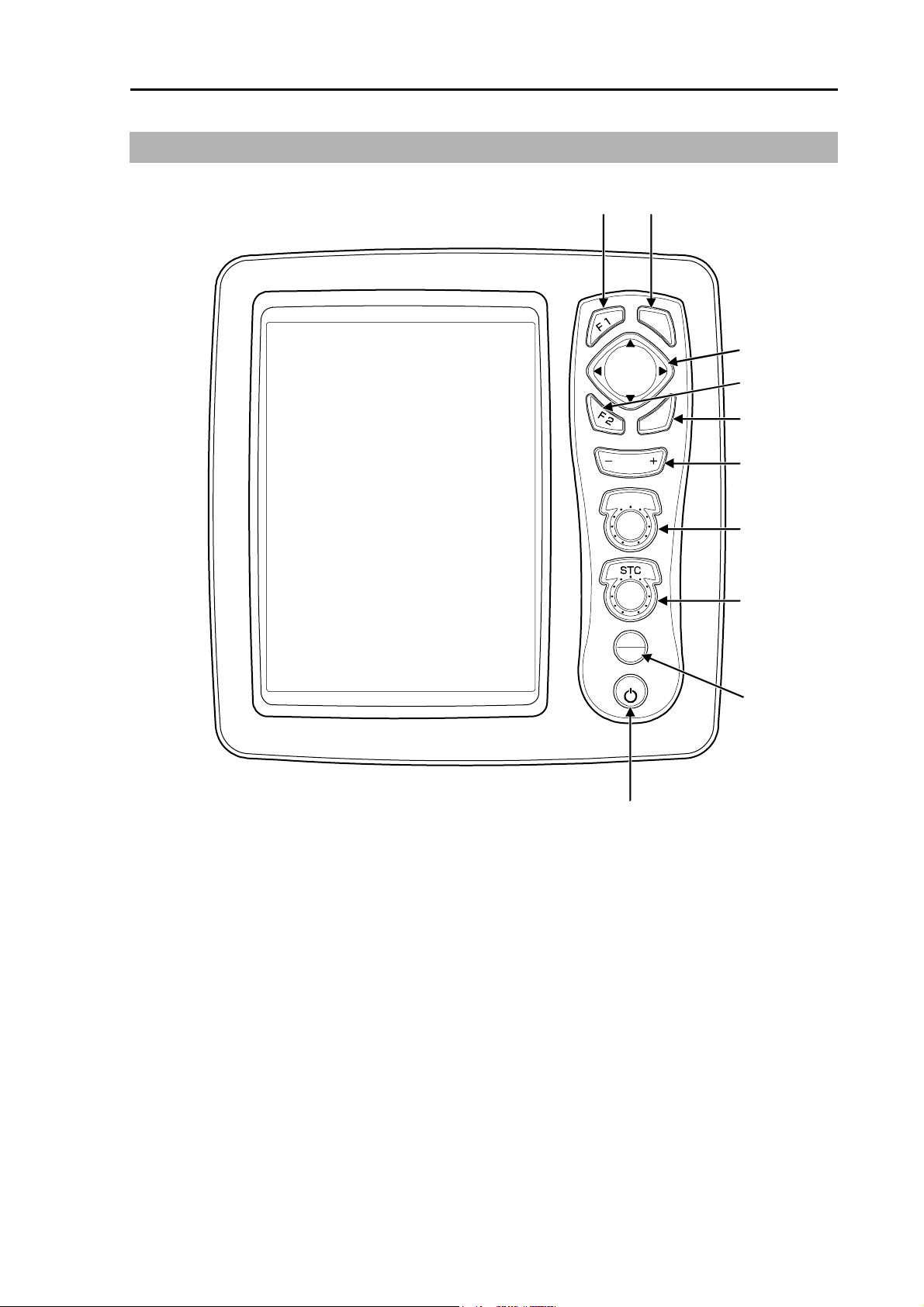
1.2 How to use the keys
(1) (2)
(3)
(4)
(5)
(6)
(7)
(8)
(9)
(10)
ENT
MENU
RANGE
GAIN
STBY
TX
BRILL
Various adjustment items can be set by operating each key.
The menu displayed by pressing the [MENU] key closes when pressing the [MENU] key again.
Chapter 1 Basic Operation T-900 series
1-5 0093142132-00
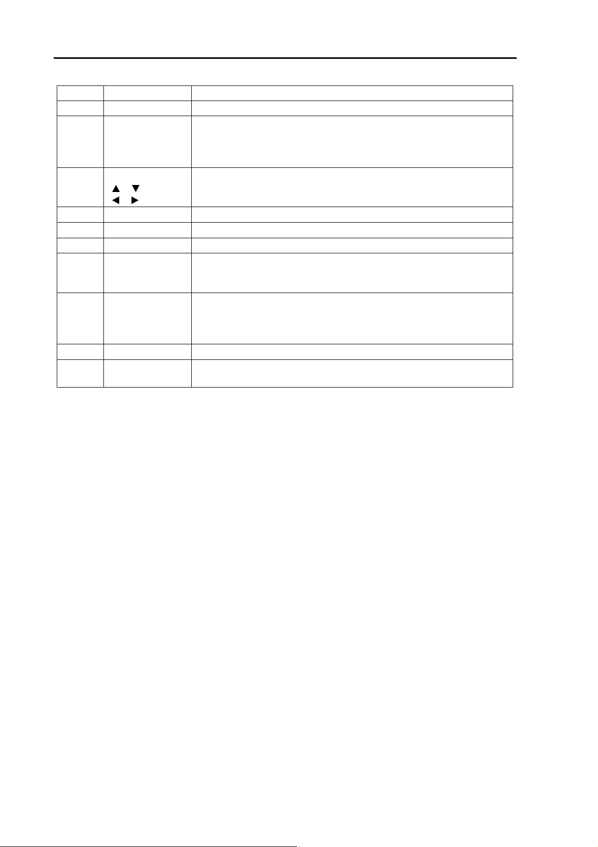
Number Key name Explanation
(1) [F1] Recalls directly the preset menu item.
(2) [ENT] Press: measures bearing of distance between two points.
Continuously pressing: Deletes the heading line. The crosshair cursor
moves to the own ship’s position.
The value in the menu is set. (Some of functions)
(3) CURSOR
[], [ ]
[], [ ]
Selects the menu item.
Changes the content of set value.
Moves the crosshair cursor.
(4) [F2] Recall directly the preset menu item.
(5) [MENU] Opens or closes the menu.
(6) [- RANGE+] Changes the range setup.
(7) [GAIN]* Rotate: Changes the gain.
Push: Changes the gain adjustment of sub-screen (lower screen of
PPI/PPI) and the range.
(8) [STC]* Rotate: Changes the STC.
Push: Display the video of a CCD camera.
When the video of a CCD camera is displayed, if you press it,
the size of video changes.
(9) [STBY/TX] Starts or stops the transmission.
(10) [BRILL]* Push: Adjusts the brilliance and the brightness of the panel.
Continuously pressing: Turns on or off the power.
* When pressed during the CCD camera video display, the display of the CCD camera video becomes
no display.
When the alarm is functioning, the alarm stops by operating any key.
Chapter 1 Basic Operation Chapter 1 Basic Operation
0093142132-00 1-6
1.3 Power On/Off
The [BRILL] key is used for both the power on/off
and the change of brilliance of the LCD and
panel.
Power On
1 Press the [BRILL] key to turn on the power.
The start-up menu is displayed. During the
display of start-up menu, the memory is
automatically checked. If the check result is
correct, the radar image appears.
Power Off
1 When turning off the power, continuously
pressing the [BRILL] key for 3 seconds.
A time required to shut down the power is
displayed on the screen.
Language Selection at Initial Start-up
When turning on the power for the first time after
[ALL RESET], the [LANGUAGE] menu appears.
1 Select the language with [ ] and [ ] keys.
When the [ ] key is pressed during display
of [LANGUAGE] menu, the menu returns to
the initial setup menu.
2 Press the [MENU] key to set the language.
1.4 Brilliance Adjustment
Brightness Adjustment of LCD
The brilliance of menu can be adjusted to make it
easier to see.
Setup: (1 to 10) (Initial value: 10)
1 Press the [BRILL] key briefly.
2 Press the [ ] and [ ] keys.
“1” is darkest. “10” is brightest.
LCD BRILL
10
3 Press the [MENU] key or [ENT] key to close
the menu.
Brightness Adjustment of Panel
The panel brightness can be adjusted,
Setup: (1 to 10) (Initial value: 10)
1 Press the [BRILL] key briefly.
When [LCD BRILL] appears, press the
[BRILL] key again.
2 Select the level with the [ ] and [ ] keys.
“1” is darkest. “10” is brightest.
PANEL BRILL
10
3 Press the [MENU] key or [ENT] key to close
the menu.
1.5 Transmission
Start of Transmission
In the 「STBY」state, when the [STBY/TX] key is
pressed, the unit starts the transmission.
After turning on the power, remaining time of
pre-heat is displayed in the center of the screen.
After 120 seconds, ST’BY appears in the center
of the screen and the unit becomes 「STBY」
state.
Stop of Transmission
In the 「TX」state, when the [STBY/TX] key is
pressed, the unit stops the transmission and
returns to the 「STBY」mode.
Chapter 1 Basic Operation T-900 series
1-7 0093142132-00
1.6 Switch-over of Range
The observation range can be changed.
Change of Range
1 Press the [- RANGE +] key.
When pressing the [+] key, an image shrinks
but the observation range expands.
When pressing the [-] key, the observation
range becomes narrow but the enlarged
surroundings around own ship can be seen.
The value of the range is displayed at the
upper left side of the screen.
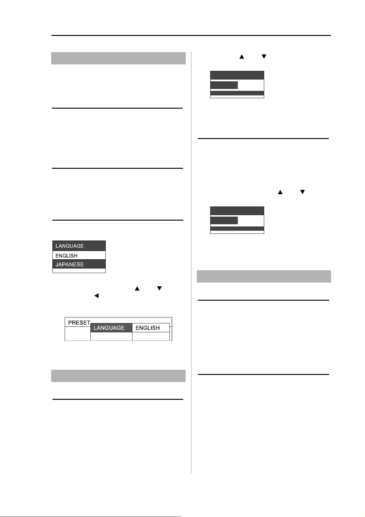
Change of Sub-screen Range
Change the range of the lower screen
(sub-screen) of the PPI/PPI menu.
For the PPI/PPI screen, refer to 2.4 Display
Select.
1 Press the [GAIN] knob.
When the [SUB-SCREEN GAIN] appears,
press the [GAIN] knob again.
2 Change the range of the sub-screen range
with the [ ] and [ ] keys.
0.75
3 Press the [MENU] key or [ENT] key to close
the menu.
1.7 Gain Adjustment
Adjust the gain according to the distance range
and reflection from the sea surface/rain/snow to
observe easily an image.
Gain Adjustment
1 When rotating clockwise the [GAIN] knob,
the gain increases.
When rotating counterclockwise the [GAIN]
knob, the gain decreases.
•When the short distance or targets are
crowded, if the gain is reduced, the image can
be easily seen.
•When the long distance, if the gain is
increased, it is effective but due to increase of
noise, the image becomes hard to be seen.
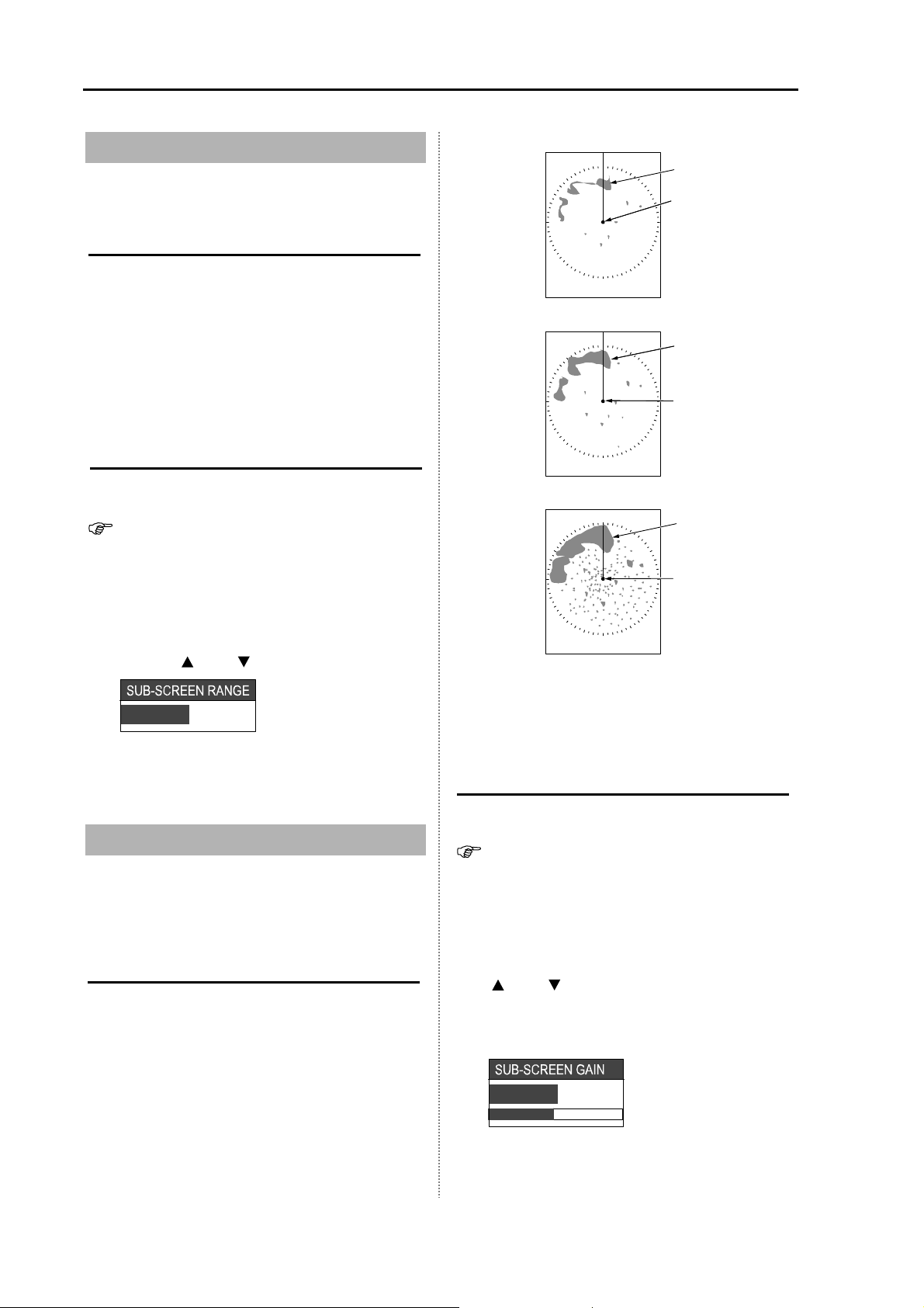
Own ship
Land
<Picture of adjusted gain>
Own ship
Land
<Picture of too low gain>
Own ship
Land
<Picture of too much gain>
Result picture after adjustment by [GAIN] knob
In the PPI/PPI menu, the gain of the upper
screen (main screen) changes when the [GAIN]
knob is adjusted.
Adjustment of Sub-screen Gain
Adjust the lower screen (sub-screen) in the
PPI/PPI menu.
For the PPI/PPI screen, refer to 2.4 Display
Select.
1 Press the [GAIN] knob.
When the [SUB-SCREEN RANGE] appears,
press the [GAIN] knob again.
2 Adjust the sub-screen gain again with the
[] and [ ] keys.
The gain increases when increasing the
numeral and decreases when decreasing the
numeral.
5.0
3 Press the [MENU] key or [ENT] key to close
the menu.
This manual suits for next models
3
Table of contents
Other Sitex Marine Radar manuals


