Sitron SC404 User manual
USER’S GUIDE
SC404
Capacitive
Level Sensor
Installation, Operation, Maintenance Instructions

Contents
3
Introduction . . . . . . . . . . . . . . . . . . . . . . . . . . . . . . . . . . . . . . . . . . . . . . . . . 4
Models & Dimensions . . . . . . . . . . . . . . . . . . . . . . . . . . . . . . . . . . . . . . . . . 5
Wiring Diagram . . . . . . . . . . . . . . . . . . . . . . . . . . . . . . . . . . . . . . . . . . . . . . 6
Mounting Note . . . . . . . . . . . . . . . . . . . . . . . . . . . . . . . . . . . . . . . . . . . . . . 12
Installation . . . . . . . . . . . . . . . . . . . . . . . . . . . . . . . . . . . . . . . . . . . . . . . . . 13
Calibration . . . . . . . . . . . . . . . . . . . . . . . . . . . . . . . . . . . . . . . . . . . . . . . . . 17
Handling . . . . . . . . . . . . . . . . . . . . . . . . . . . . . . . . . . . . . . . . . . . . . . . . . . 19
Technical Specifications . . . . . . . . . . . . . . . . . . . . . . . . . . . . . . . . . . . . . . 20
Trouble Shooting . . . . . . . . . . . . . . . . . . . . . . . . . . . . . . . . . . . . . . . . . . . . 21
Ordering Information . . . . . . . . . . . . . . . . . . . . . . . . . . . . . . . . . . . . . . . . . 22
Terms & Conditions . . . . . . . . . . . . . . . . . . . . . . . . . . . . . . . . . . . . . . . . . 23
4
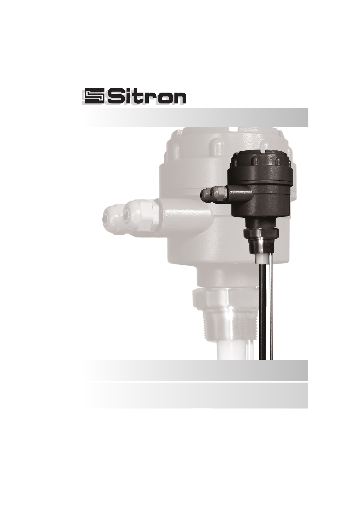
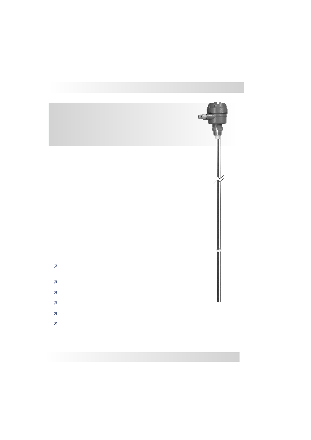
SC404 - Capacitive
Level Sensor
The SC404 is a capacitance continuous level transmitter with an
integrated electronics module mounted within the housing. This 2 wire
loop powered unit provides a 4-20mA output (galvanically isolated).
Set up and calibration is achieved with a zero and span adjustment
which works best when starting with an empty tank to set the zero and
then filling it to set the span. This flexible level measurement device
works well in many industrial processes and process media including
a variety of liquids, powders and pastes. The SC404 is made with
316SS rigid rods or 316SS cables (coatings are required for
conductive mediums) and can also be made with a secondary
reference rod or reference sheath built into the process connection.
The wide range of applications for RF analog level measurement
probes (such as liquids, pastes, solids and granules), requires
attention in selecting the correct configuration and installing it in the
proper location. To cater to all applications, Sitron's probes are offered
with different designs and features.
Wide range of applications/industries:
i.e. water, oils, corrosives, solids, powders, grains, etc.
Accurate and reliable measurement
No moving parts - Rugged construction
Can operate at high temperatures and pressure
Functions on conductive as well as non-conductive medias
Galvanic Isolation
Features
Introduction
Sitron-USA - Phone (516) 935-8001 / Fax (800) 516-1656

5
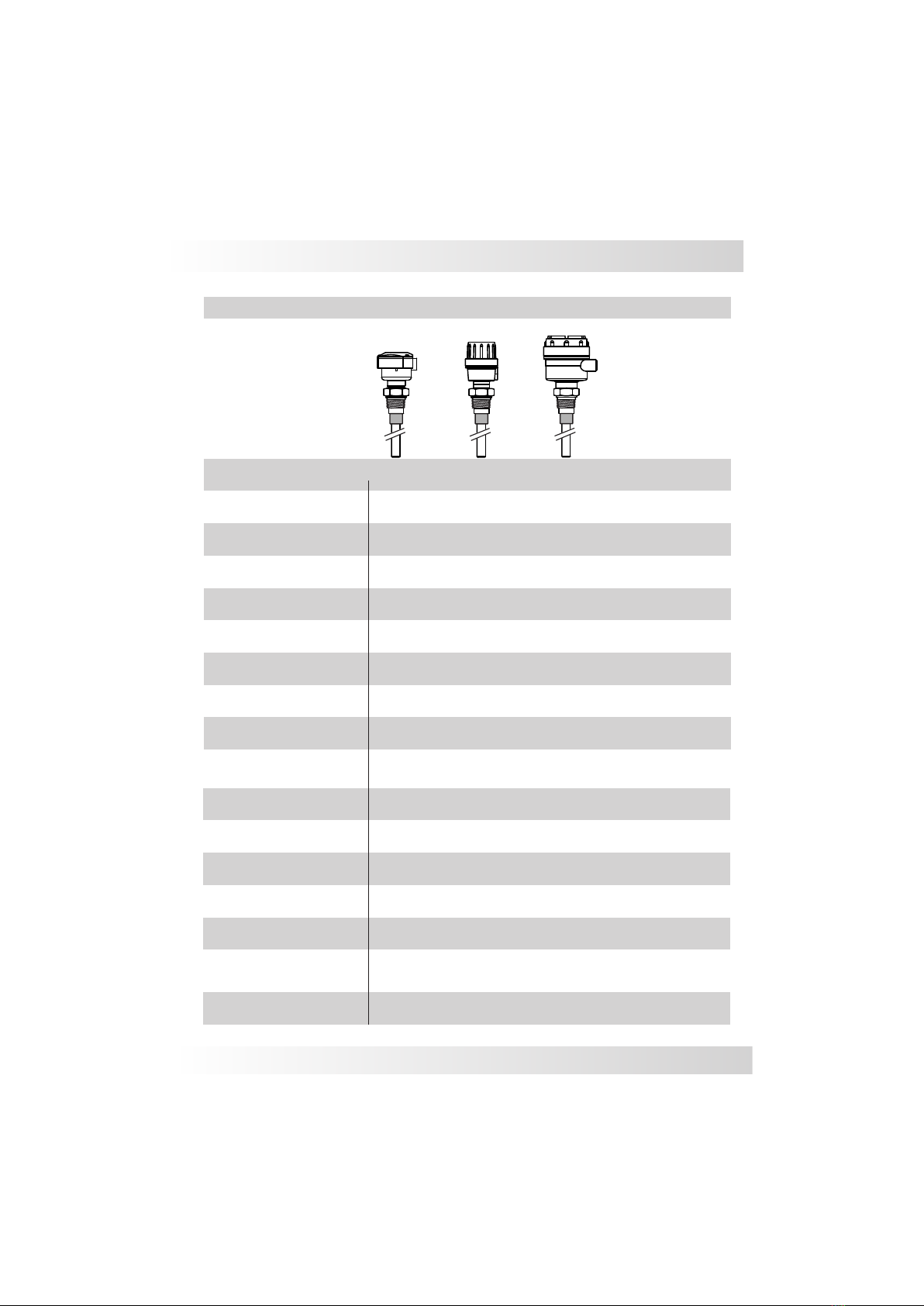
Models and Dimensions
Threaded
SC404 W/
Reference Sheath
SC404 W/
Reference Rod
SC404 w/ Cable
(also w/ reference cable)
SC404 Standard
Note: Minimal insertion for the SC404 is ½ meter
Extended necks for medium temperature (up to 120°C)
3/4”
1 ½”
1 ½”
1 ½”
2 ½”
2 ½”
1”
2”
2”
2”
3”
N1- Nylon G1-Aluminum G2 - Aluminum
1”
1,75
Tri-Clamp Flange
Housing Types
Mounting Options for SC404
Process Connections
TC Connection
ANSI 150#
ANSI 300#
Rubber Seal
Process Connection
NPT BSP FF
RF
L
20
½”
1,6
1”NPT
1”NPT
½”
½”
L
25
66
1/4”
1 1/2”NPT
L
20
50mm
126mm
130mm
130mm 118mm
89mm
76mm
89mm 80mm
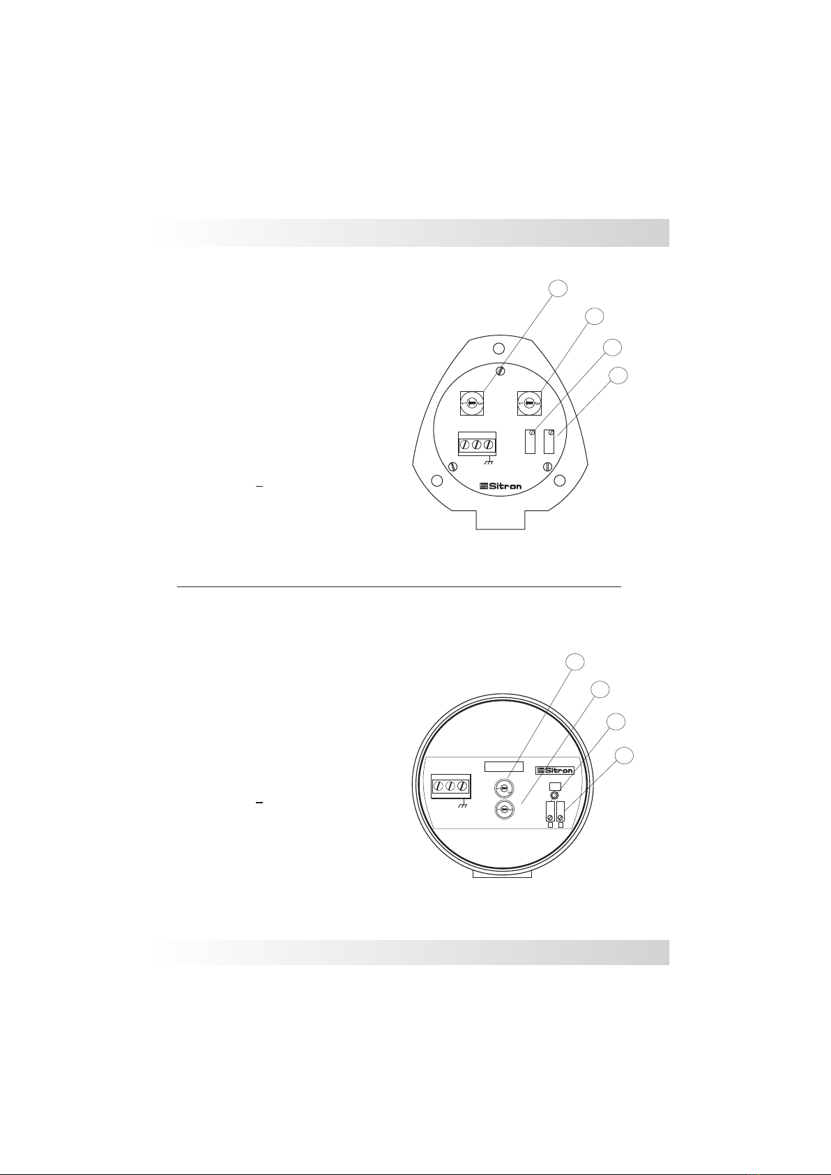
SC404 with N1 Housing
0
2
0
2
Span
Zero
Gain
SC404
Sub
+_
123
1
+_
23
0
2Gain
SC404-G
On
S
Z
SC404 with G1 Housing
1- Power Supply (+)
2- Power Supply ( )
3- Ground
24Vdc / 4...20mA
C
A
D
B
A- Adjust Sensibility (Gain)
B- Adjust Sensibility (Sub gain)
C- Adjust Zero (begin scale)
D- Adjust Span (end of scale)
A
B
C
D
1- Power Supply (+)
2- Power Supply ( )
3- Ground
24Vdc / 4...20mA
A- Adjust Sensibility (Gain)
B- Adjust Sensibility (Sub gain)
C- Adjust Zero (begin scale)
D- Adjust Span (end of scale)
Sitron-USA - Phone (516) 935-8001 / Fax (800) 516-1656
0
2
Sub
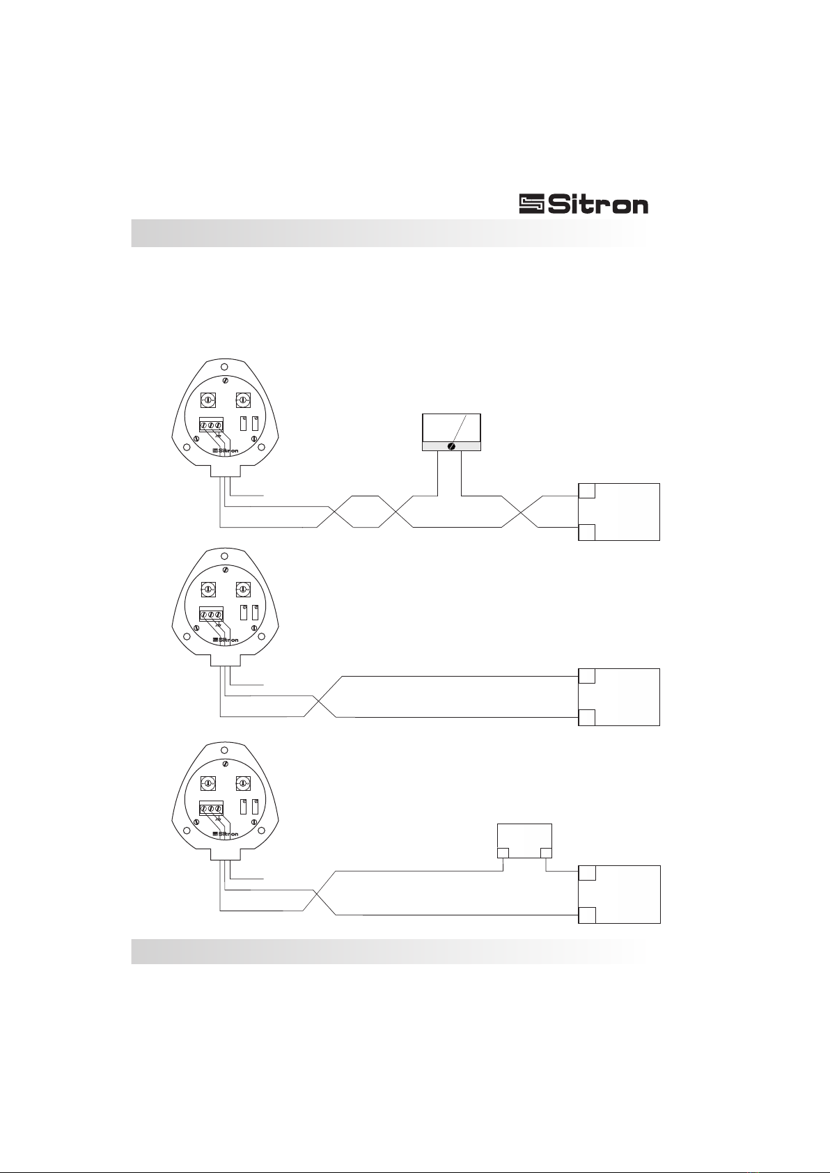
Wiring Diagram
6

SC404 with G2
A
B
C
Wiring Diagram
1
24Vdc
(+-10%)
+
4...20mA
2
-
3
D
On
Gain
0
2
Zero
Sub
0
2
Span
SC 404
7
1- Power Supply (+)
2- Power Supply ( )
3- Ground
24Vdc / 4...20mA
A- Adjust Sensibility (Gain)
B- Adjust Sensibility (Sub gain)
C- Adjust Zero (begin scale)
D- Adjust Span (end of scale)
8
Wiring Diagram
Sitron-USA - Phone (516) 935-8001 / Fax (800) 516-1656
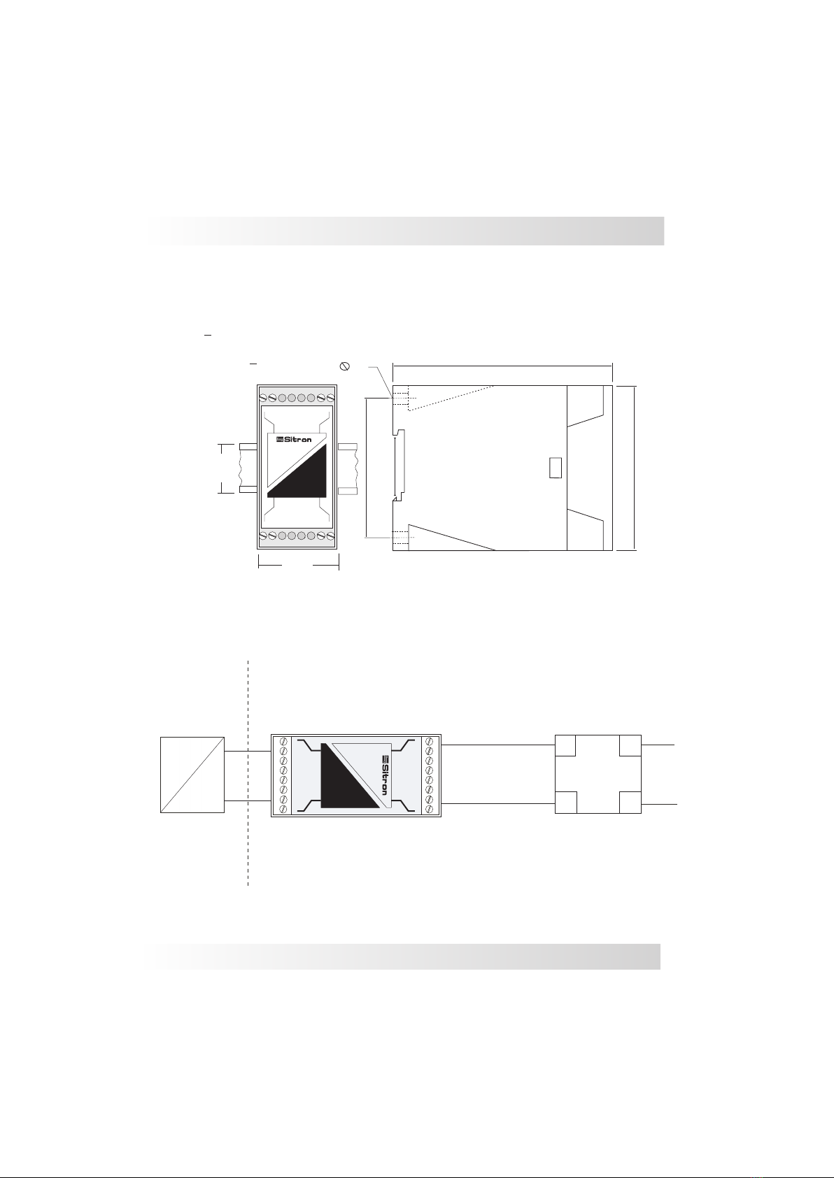
Galvanic Isolator - ISO420
1- Probe (+)
2- Probe( )
11- Power Supply (+)
12- Power Suppy ( ) 6mm
69.8mm
DIN 35mm
111mm
83.5mm
35mm
44mm
in 24 VDC
4...20mA
4...20mA
Zone 0
out
ISO 420
11+ -12
1+ -2
L1
in _
11+
1 + 2
_
12
4...20mA
4...20mA
Zone 0
out
ISO 420
+
-
+
-N
Security Barrier ISO 420 PLC
4...20mA
Transmitter
4...20mA
9
Wiring Diagram
Electrical connection using the Galvanic Isolator for a PLC with an active input card.
Electrical connection using the Galvanic Isolator for a PLC with a passive input card.
Connecting directly into the power supply
Active PLC input card
Passive PLC input card
___
+++
PLC
___
+++
Power
Supply
4 ... 20 mA
0 ... 100 %
___
___
+++
+++
Power
Supply
PLC
+
+
+
-
-
-
Ground
Ground
Ground
Different wiring scenarios for the N1 electronics
0
2
0
2
0
2
0
2
0
2
0
2
Span
Span
Span
Zero
Zero
Zero
Gain
Gain
Gain
SC404
SC404
SC404
Sub
Sub
Sub
10...30VDC
10...30VDC
10...30VDC
4...20mA
4...20mA
4...20mA
+
+
+
_
_
_
1
1
1
2
2
2
3
3
3
24Vdc
24Vdc (+/- 10%)
24Vdc (+/- 10%)
10
Wiring Diagram
Connecting directly into the power supply
Active PLC input card
Passive PLC input card
___
+++
PLC
___
+++
Power
Supply
4 ... 20 mA
0 ... 100 %
___
___
+++
+++
Power
Supply
PLC
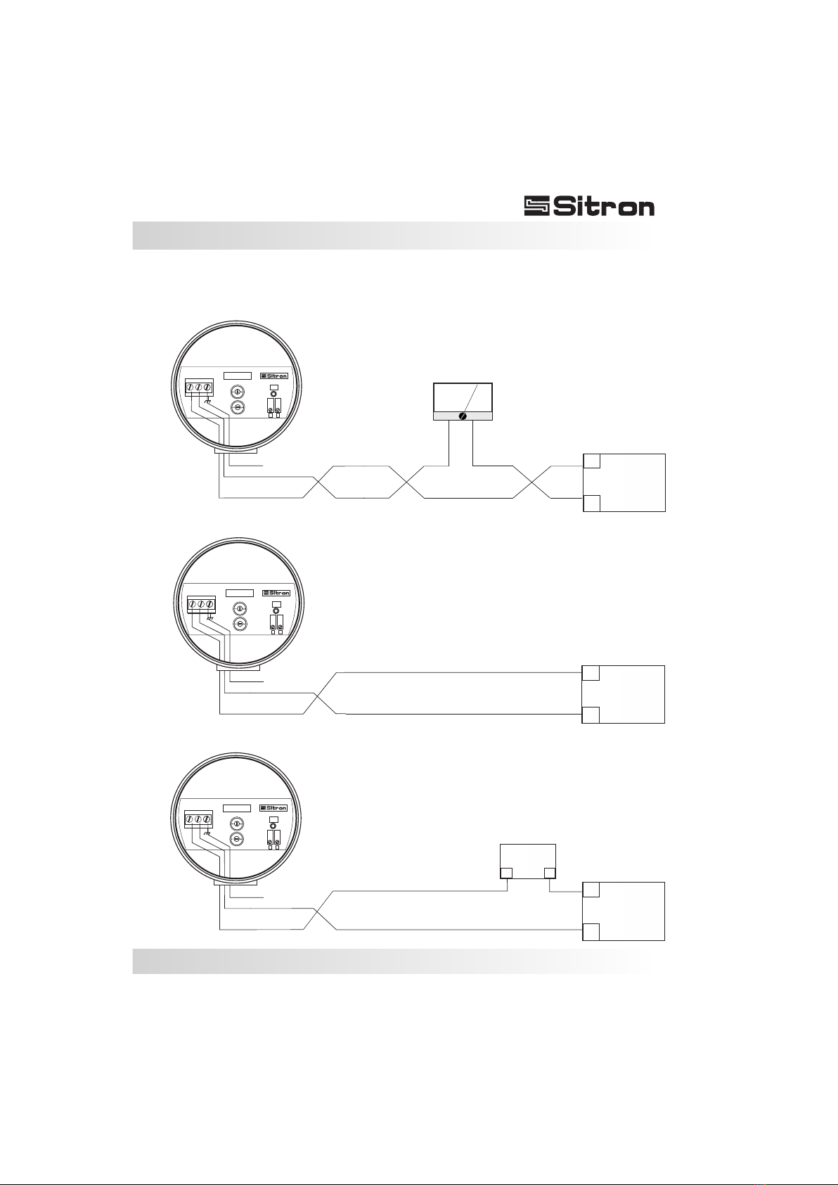
Different wiring scenarios for the G1 electronics
1
+_
23
V=10...30VDC
I=4...20mA
0
2
Gain
SC404-G
On
S
Z
+
-
Ground
1
1
+
+
_
_
2
2
3
3
V=10...30VDC
V=10...30VDC
I=4...20mA
I=4...20mA
0
0
2
2
Gain
Gain
SC404-G
SC404-G
On
On
S
S
Z
Z
+
+
-
-
Ground
Ground
0
2
Sub
0
2
Sub
0
2
Sub
12...30Vdc
24Vdc (+/- 10%)
24Vdc (+/- 10%)
11
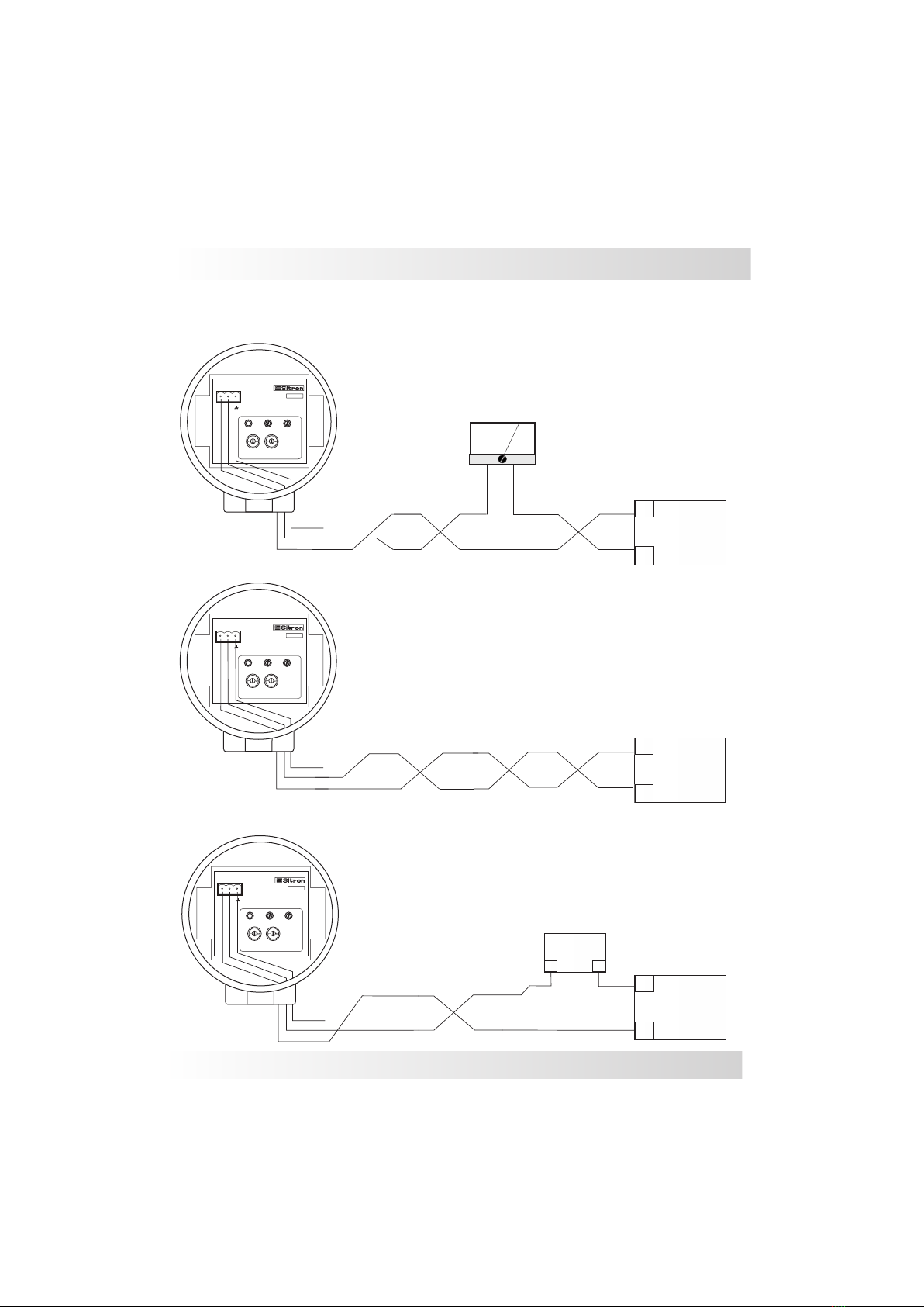
Wiring Diagram
Electrical connection for a PLC with an active input card.
Electrical connection for a PLC with a passive input card.
Connecting directly into the power supply
Active PLC input card
Passive PLC input card
___
+++
Power
Supply
4 ... 20 mA
4 ... 20 mA
4 ... 20 mA
0 ... 100 %
___
___
___
+++
+++
+++
Power
Supply
PLC
PLC
+
+
+
-
-
-
Ground
Ground
Ground
Different wiring scenarios for the G2 electronics
The G2 offers a built in galvanic isolator. In this case a separate one is not necessary.
0
0
0
2
2
2
0
0
0
2
2
2
Span
Span
Span
On
On
On
Zero
Zero
Zero
Gain
Gain
Gain
Sub
Sub
Sub
1
1
1
2
2
2
3
3
3
SC 404
SC 404
SC 404
24Vdc
24Vdc
24Vdc
(+-10%)
(+-10%)
(+-10%)
+
+
+
-
-
-
4...20mA
4...20mA
4...20mA
Sitron-USA - Phone (516) 935-8001 / Fax (800) 516-1656
24Vdc (+/- 10%)
24Vdc (+/- 10%)
24Vdc (+/- 10%)
12
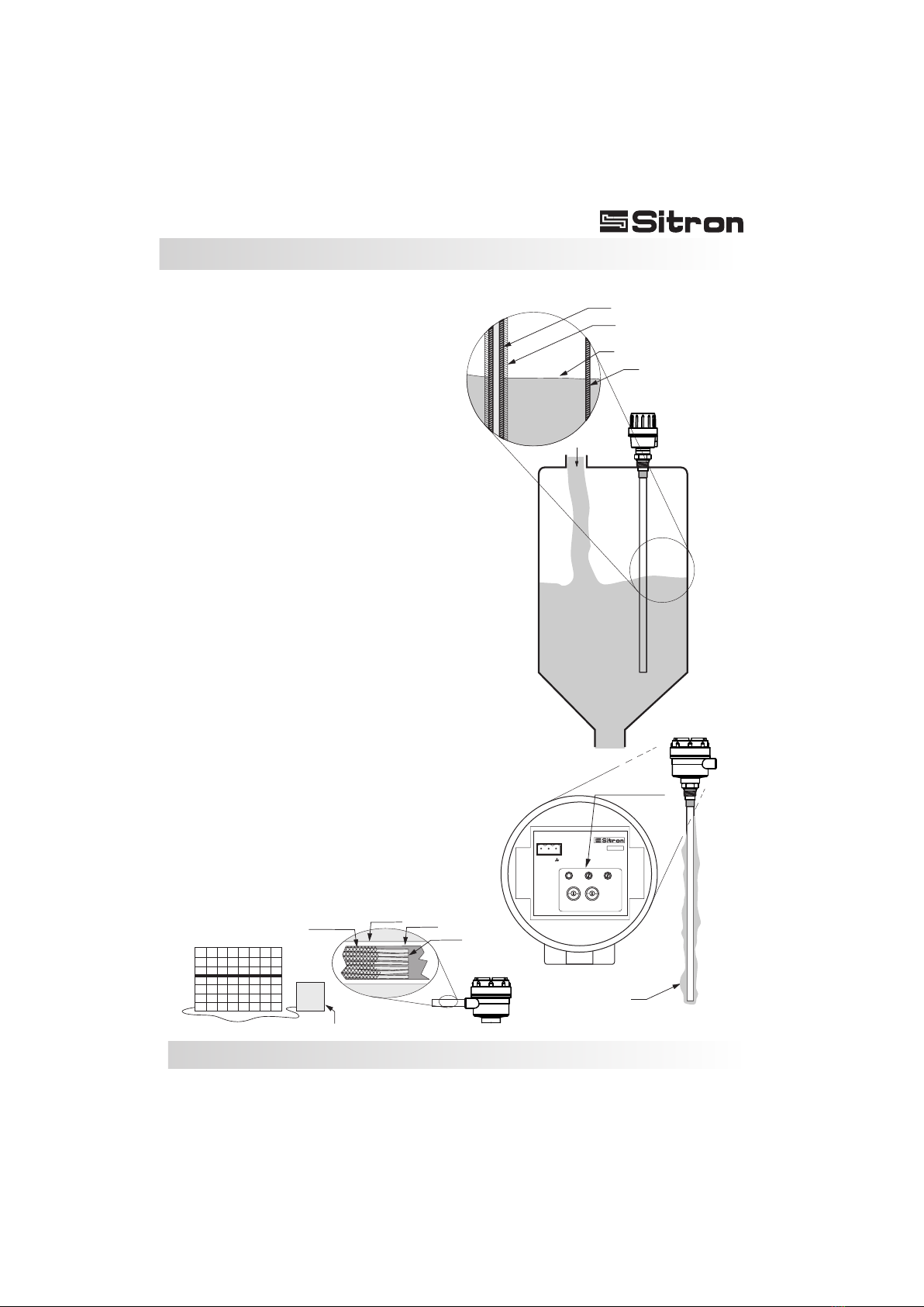
Mounting Note
Materials that are conductive will cause a
short circuit between a bare stainless steel
probe and the tank wall. For that reason we
recommend the use of Teflon or other types
of insulating coatings on the rod's surface
(Fig. 1)
Material build-up also affects the accuracy
of RF capacitive measurements, and
therefore additional adjustment to the
probe's sensitivity is recommended in
applications where build-up is a concern
(Fig. 2)
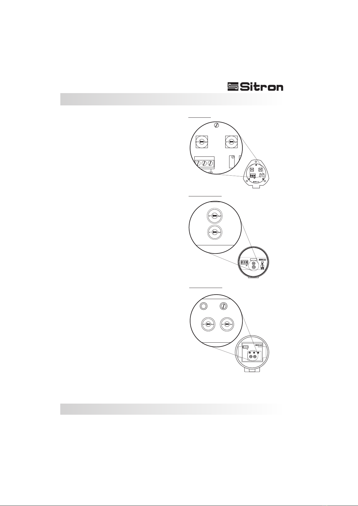
Housings must also be compatible with the
requirements for wash-down, wet, and/or
d u s t y e n v i r o n m e n t s . H a z a r d o u s
environments may require the housing to be
certified. In addition, the active probe might
need to be intrinsically safe or have an
intrinsic safety barrier (Fig. 3).
The electronic circuitry of the probe
performs several functions such as
rectifying and filtering the incoming power,
generating the radio frequency signal,
measuring the changes in current flow,
analog signal generators and display
meters. The circuitry is provided with
potentiometer adjustments for setting
sensitivity that is located in the housing of
the probe. These adjustments give an
added level of fine-tuning which enable our
customers to control the probe's sensitivity
with greater accuracy (Fig. 3).
Variation in current input (power supply) to
the probe will affect the output. Therefore, a
stable power supply should be available
(Fig. 4).
Coating (PTFE or Halar)
Bare Rod
Fig. 1
Fig. 2
Fig. 4
Fig. 3
Steel Tank
Conductive Medium
Adjust Sensitivity
Build up
Power Supply Conduit
Conduit Cable
Wires
Wire Shield
0
2
0
2
Span
On Zero
Gain Sub
123
SC 404
24Vdc
(+-10%)
+
-
4...20mA
13
Sitron - Equip. Eletrônicos Ltda. - Fone/Fax (5511) 3825-2111 / 3825-2171
500mm
100mm
Fig. 2
Fig. 1
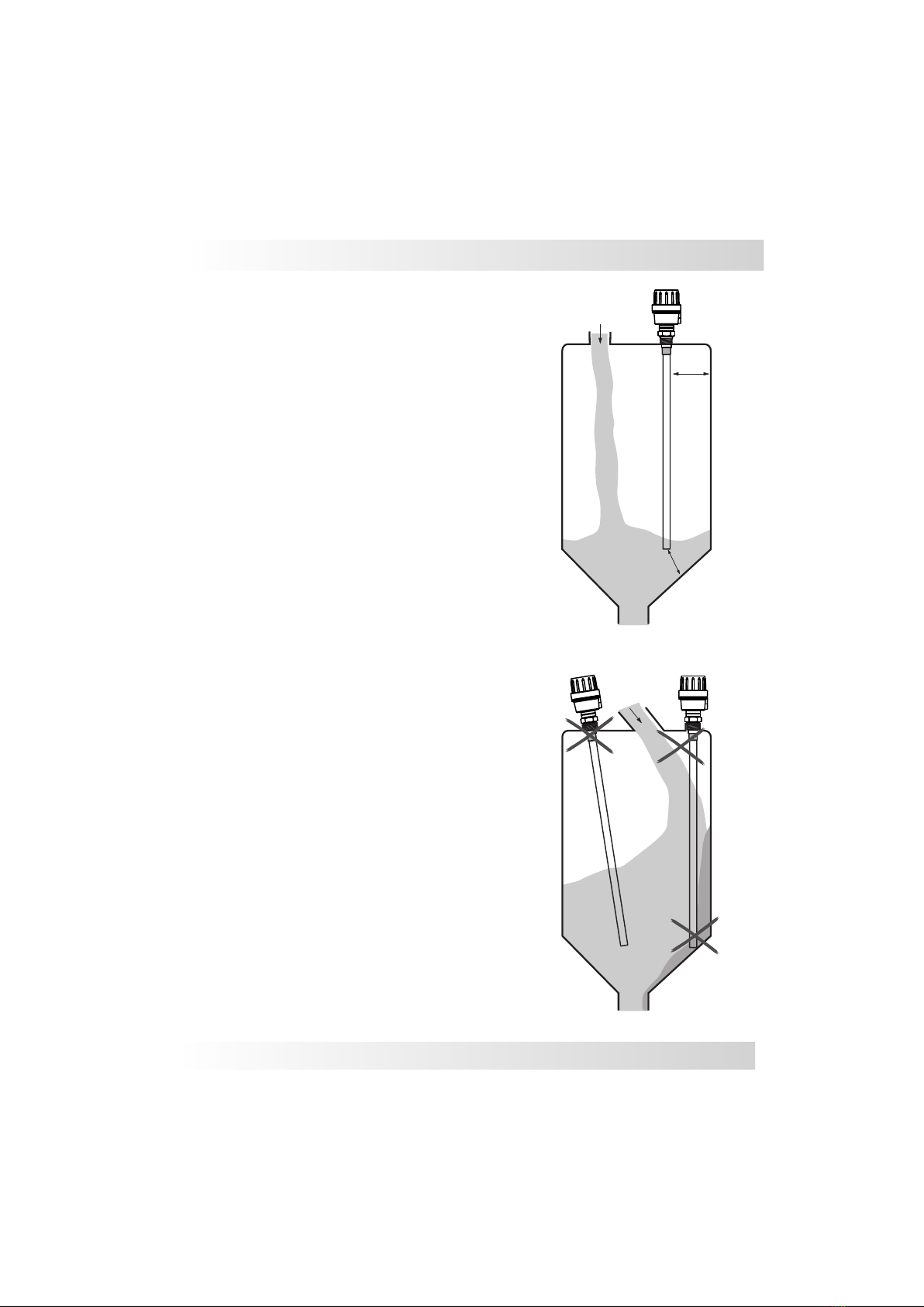
When installing the probe either directly to the
tank, or utilizing a connection, the capacitance
probe should be mounted on the top of the tank,
never on the side or angle, so that the rod stays
parallel to the tank wall (Fig. 1 correct Fig. 2
Incorrect).
The mounting location of the probe should stay
clear away from the point where the medium
enters, this will avoid false reading from the sensor
while being filled (Fig. 1 correct Fig. 2 Incorrect).
The recommended distance of installation of the
probe from the internal wall is a minimum of
500mm, and from the tip of the rod to the bottom of
the tank is 100mm, this will prevent a false signal
and possible build up between the wall and probe
(Fig. 1 correct Fig. 2 Incorrect).
Installation

14
The tank must be free from turbulence or
vortices throughout use. If this is not
possible we highly recommend a stilling
well or sheath (Fig. 1 correct, Fig. 2
incorrect).
Ensure that mounting position does not
interfere with any obstructions wthin the
vessel or tank (Fig. 1 correct, Fig. 2
incorrect).
Fig. 1
Fig. 2
Level
Rod
Sheath
Installation

Sitron-USA - Phone (516) 935-8001 / Fax (800) 516-1656
Installation
When installing the SC404 with cable and
reference be sure that they are well connected
to the bottom of the tank and that it has no slack.
(Fig. 1 correct Fig. 2 Incorrect).
The mounting location of the probe should stay
clear away from the point where the medium
enters, this will avoid false reading from the
sensor while being filled (Fig. 1 correct Fig. 2
Incorrect).
The recommended distance of installation of
the probe from the internal wall is a minimum of
500mm, and from the tip of the pendulum to the
bottom of the tank is 100mm, this will prevent a
false signal and possible build up between the
wall and probe (Fig. 1 correct Fig. 2 Incorrect).
If the cable is secure to the bottom of the vessel
it must be isolated and the vessel is steel it must
be isolated so that it does not create a short
circuit.
Fig. 1
Fig. 2
500mm
100mm
Isolator
15
Installation
Fig. 2
Fig. 1
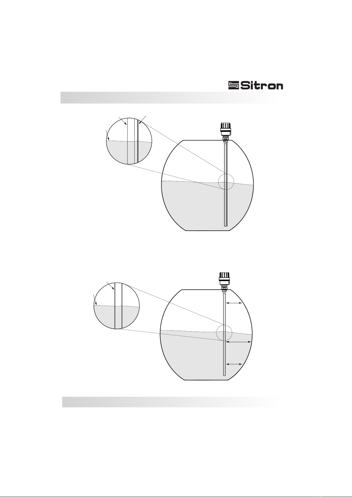
In order to achieve a linear output
signal, the main rod of the probe
must have a parallel reference
either to the tank or to a
secondary reference rod or
sheath. If the probe is mounted
without this parallel reference
within a cylindrical tank that is
mounted on its side, the output
signal will not be linear. Please
consult one of our applications
engineers if you have further
questions (Fig.1 correct Fig. 2
incorrect).
L=y
L=z
L=x
Level
Level
Rod
Single Rod
Reference Rod
16

Sitron-USA - Phone (516) 935-8001 / Fax (800) 516-1656
Calibration
8) With the 20mA signal adjusted it is best to re-
adjust the Zero. Drain the tank back down to the
starting level and re-adjust (if necessary) the
minimum level to 4mA one more time. After this
stage, set-up is complete.
Adjustment (4-20mA):
It is recommended that an multimeter be connected
according to the figure below (fig.5) to monitor the
current value during the calibration.
1) Drain the tank to minimum level (Zero% or 4mA).
2) Select the Gain switch 1,2,3 and Sub positions
1,2 or 3. It is recommended to begin with Gain switch
1 and Sub position 1 (Fig. 2).
3) Use the Zero potentiometer to set the current
value for the actual level to 4mA. Turn the
potentiometer clockwise to increase current. Turn
the potentiometer counter-clockwise to decrease
current (If the adjustment wasn't possible, alter the
Sub and Gain position and try in adjust the minimum
value (4mA) through the Zero Potentiometer)(Fig.3)
4) After calibrating the minimum value (4mA), fill up
the tank to maximum level (100% - level).
5) The Sub and Gain switches should be in the same
position as adjusted to 4mA.
6) Use the Span potentiometer to set the current
value for the actual level to 20mA. Turn the
potentiometer clockwise to increase current. Turn
the potentiometer counter-clockwise to decrease
current (Fig.4).
7) If the current is lower than 20mA after fully turning
the Span Potentiometer clockwise, it is necessary to
increase the sensitivity by selecting the next level of
the switch (Sub and Gain). If the current still remains
lower than 20mA, continue on to the next level until
you achieve 20mA.
0
0
0
0
2
2
2
2
0
0
0
0
2
2
2
2
Span
Span
Span
Span
On
On
On
On
Zero
Zero
Zero
Zero
Gain
Gain
Gain
Gain
Sub
Sub
Sub
Sub
Fig.2
Fig.3
Fig.4
Fig.5
17
Nylon-N1
Aluminum-G1
Aluminum-G2
0
2
0
2
Span
On Zero
Gain Sub
123
SC 404
24Vdc
(+-10%)
+
-
4...20mA
0
2
0
2
Span
Zero
Gain
SC404
Sub
10...30VDC
4...20mA
+_
123
1
+_
23
V=10...30VDC
I=4...20mA
0
2
Gain
SC404-G
On
S
Z
0
2Gain
0
2
0
2
Zero
Gain
SC404
Sub
+_
123
0
2
On Zero
Gain Sub
0
2
Calibration
The dielectric value varies according to
the product, temperature, pressure,
rod's length and shape of the tank.
Because of these variations, the
parameters of the capacitive probe need
to be adjusted according to each
application as well as each tank. While
the SC404 can be tested on a bench, the
results of calibrating it will not be the
same as calibrating the unit within the
actual tank that you plan on installing it in.
The SC 404 has 3 stages of sensitivity
and that can be adjusted by a selective
switch. Each stage has 3 subdivisions
(1, 2, 3) for the SC404 and 4 subdivisions
(1, 2, 3, 4) for the SC404-G to be
combined with the selective switch.
Check the values on the chart below
according to your application.
Capacitive Range for the SC404-G:
Gain Sub
1) 1600pF to 5500pF 1 - 3750 to 5500pF
2 - 2500 to 3750pF
3 - 1600 to 2500pF
2) 400pF to 1500pF 1 - 900 to 1500pF
2 - 600 to 900pF
3 - 400 to 600pF
3) 100pF to 330pF 1 - 225 to 330pF
2 -150 to 225pF
3 -100 to 150pF
4) 25pF to 150pF 1 - 150 to 100pF
2 -100 to 70pF
3 - 70 to 25pF
0
2
Sub
0
2
Sub
18
19
Sitron-USA - Phone (516) 935-8001 / Fax (800) 516-1656
Handling
Probes:
Care should be taken when handling and installing
probes with coated rods to avoid scratching them.
Scratching the coating could interfere with the
probe performance.
Periodic visual inspection of the probe is required
to check for corrosion or deposit build-up. If
deposits are found, clean the sensor to ensure
optimum performance.
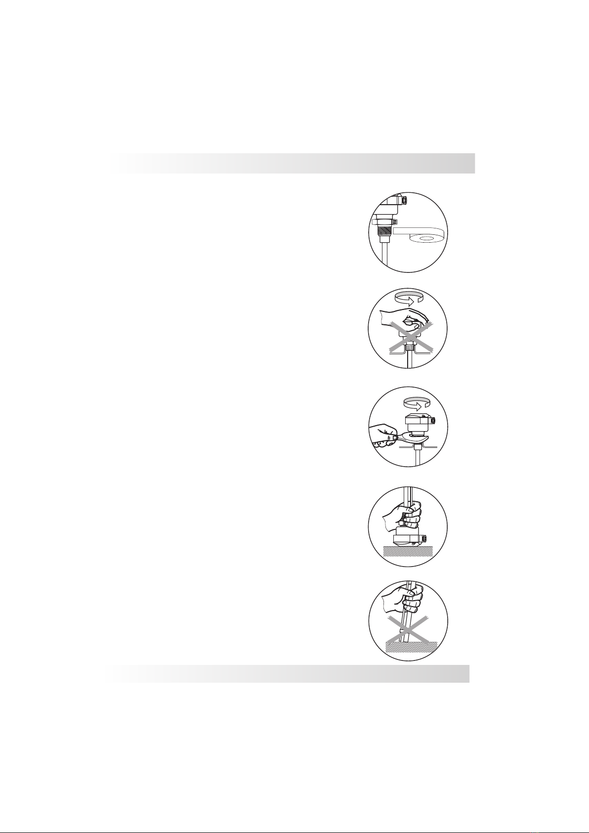
The probe should not be dropped or suffer any
impact or fall that could damage the electronics or
the coating of the probe (Fig. 4 and 5).
Seal the thread with Teflon tape before
installation (Fig. 1).
Do not turn or handle by the housing (Fig. 2).
When tightening the sensor, use only use the
316S.S. hexagon fitting to achieve a seal, do not
twist with the body of the sensor. (Fig. 3)
When cleaning the rod use a soft brush or any
other similar object.
Fig. 2
Fig. 3
Fig. 4
Fig. 5
Fig. 1
20
Technical Specifications
Sitron-USA - Phone (516) 935-8001 / Fax (800) 516-1656
SC404
22mA max
24Vdc (+/- 10%)
Application
Operating Voltage
Current Consumption
Electrical Connection
Ambient / Operating temp.
Cable gland - 1/2” NPT conduit entry or M12 connector
Output
Max Pressure
IP 65 (N1)
IP66 (G1/G2)
Accuracy
Enclosure Material Glass filled nylon, Aluminum
Wetted Parts 316 Stainless Steel, PTFE
Class Protection
Process Connection
Adjustment
Sensitivity Range
Frequency Oscillation
Zero & Span Potentiometer
4...20mA (2 wires)
100 to 5500pF
400 kHz
Continuous Level Measurement for Liquids and Solids
290 PSI (20 Bar)
0.5%
3/4” to 1 1/2” BSP or NPT Flange or Sanitary Connections
-10 to 60ºC / -10 to 80°C (120°C extended neck)
G2G1N1
Galvanic Isolation 3KVdc/60s
100M ohms, 500VDC

21
Trouble Shooting
No signal
Signal over
22mA
Signal under
20mA
Lack of linearity
Probable short circuit
Sensitivity to high
Sensitivity to low
Reference is incorrect
Add a Reference
Sheath the rod
Coating on the rod
is damaged Send back for repair
Lack of signal from
referance rod
Signal Fluctuating
No power supply
Verify the grounding
Verify that the rod is coated for
conductive mediums
Adjust sensibility again
Adjust sensibility again
Verify power supply
Fault Cause Solution
Verify the polarity of the power supply
Inadaquate connection
Sitron-USA - Phone (516) 935-8001 / Fax (800) 516-1656
Table of contents
Popular Accessories manuals by other brands

Equalizer
Equalizer Livewire LFT412 user guide

Silvercrest
Silvercrest SPS 5000 A1 operating instructions

Silvercrest
Silvercrest SPB 10000 A1 operating instructions

Heath Zenith
Heath Zenith Notifi Elite owner's manual

Alarmcom
Alarmcom Flex IO installation guide

Heath Zenith
Heath Zenith 6106 installation guide


