SITRONICS TLM1710EU User manual

DESIGNS AND SPECIFICATIONS ARE SUBJECT TO CHANGE WITHOUT NOTICE
SERVICE MANUAL
SERVICE MANUAL
17" TFT-LCD TV/MONITOR
MODEL: TLM1710EU

-2-
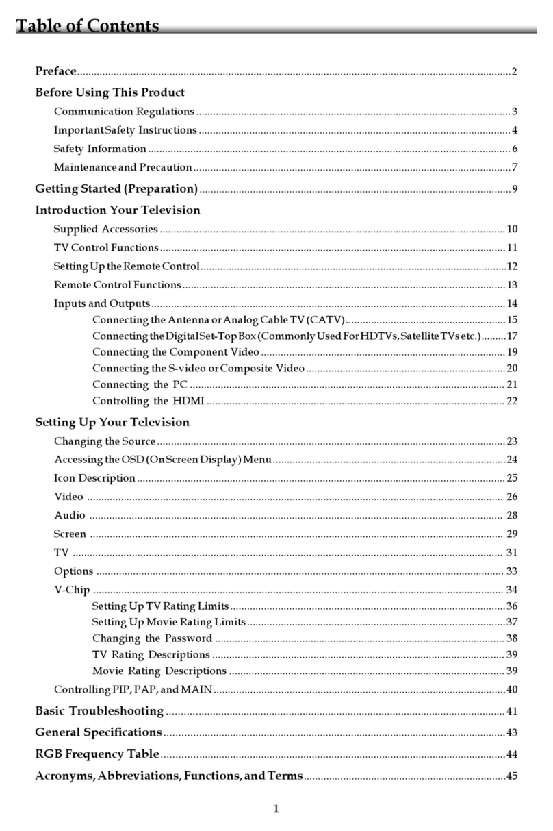
TABLE OF CONTENTS
Location and Function of Controls --------------------------------------------------------------- 3
Remote controller ---------------------------------------------------------------------------------- 3
Front Panel Control -------------------------------------------------------------------------------- 5
PCB Component List -------------------------------------------------------------------------------- 35
DRIVE PCB Assembly --------------------------------------------------------------------------- 38
Electronic Common Part Assembly ----------------------------------------------------------- 35
Tuning PCB Assembly --------------------------------------------------------------------------- 35
VIDEO-INPUT PCB Assembly ------------------------------------------------------------------ 35
AUDIO PCB Assembly --------------------------------------------------------------------------- 36
TELETEXT PCB Assembly ---------------------------------------------------------------------- 37
Control Key PCB Assembly --------------------------------------------------------------------- 37
AUDIO-INPUT PCB Assembly ----------------------------------------------------------------- 37
Information Of ICs ----------------------------------------------------------------------------------- 28
Exploded View and Mechanical Parts List ---------------------------------------------------- 26
MAIN Unit Explode view ------------------------------------------------------------------------- 26
Stand Base Block Explode view --------------------------------------------------------------- 27
Wiring Diagram --------------------------------------------------------------------------------------- 25
Block Diagram ----------------------------------------------------------------------------------------- 24
Printed Circuit Board ------------------------------------------------------------------------------- 13
AUDEO Board ------------------------------------------------------------------------------------- 13
DRIVE Board -------------------------------------------------------------------------------------- 15
TUNER Board ------------------------------------------------------------------------------------- 17
KEY Board ----------------------------------------------------------------------------------------- 18
AINPUT Board ------------------------------------------------------------------------------------ 20
VIDEO INPUT Board ---------------------------------------------------------------------------- 22
Schematic Diagrams ---------------------------------------------------------------------------------- 7
AV Schematic Circuit ------------------------------------------------------------------------------- 7
DRIVE Schematic Circuit ------------------------------------------------------------------------- 8
KEY Schematic Circuit ---------------------------------------------------------------------------- 10
AINPUT&TUNER Schematic Circuit ----------------------------------------------------------- 11
VIDEO Input Schematic Circuit ----------------------------------------------------------------- 12
Installation and connecting ------------------------------------------------------------------------- 6

-3-
Location and Function of Controls
SOURCE DISPLAY MUTE
1234
567
9
8
0
RETURN
MENU
PICTURE MODE SOUND
BBE
NICAM/A2
SYSTEM
TEXT MIX HOLD INDEX
CANCEL SIZE REVEAL SUBPAGE
RED GREEN YELLOW CYAN
STANDBY
All the functions can be controlled with the
remote controller. Some functions can
also be adjusted with the buttons on the front
panel of the set.
1
2
3
4
6
7
5
8
Remote controller
1. STANDBY
To switch the unit on or off from standby.
2. SOURCE
To Select TV, AV (Video/S-Video/YUV)
or PC monitor mode.
3. NUMBER BUTTONS
To directly select programme number.
4. TWO-DIGIT NUMBER BUTTON
To switch one or two-digit programme
number
5. RETURN
To return to previously selected
programme number .
6. PICTURE
To select picture control (brightness/
contrast/color).
8. MENU
To enter into or exit out of the menu
(AV/TV mode).
To accept your selection (PC mode).
7. (VOLUME UP/DOWN)
To increase or decrease the volume.
To adjust menu settings.
(PROGRAMME UP/DOWN)
To select programme or a menu item.

-4-
Location and Function of Controls
SOURCE DISPLAY MUTE
1234
567
9
8
0
RETURN
MENU
PICTURE MODE SOUND
BBE
NICAM/A2
SYSTEM
TEXT MIX HOLD INDEX
CANCEL SIZE REVEAL SUBPAGE
RED GREEN YELLOW CYAN
STANDBY
9
10
11
12
14
15
13
16
9. MUTE
To switch on sound mute or turn off
sound mute.
10. DISPLAY
To display setup information channel.
11. MODE BUTTON
To adjust the picture mode (user/soft/
dynamic/stanard).
12. SOUND BUTTON
To adjust the sound effect.
13. BBE BUTTON
To switch BBE on or off.
14. SYSTEM
To select TV system.
15. NICAM/A2 BUTTON
To switch between NICAM , A2 and
mono sound output.
16. TELETEXT BUTTONS (OPTION)
These buttons are used for teletext.

This TFT-LCD TV/monitor allows you toeasily adjust thecharacteristics of the
image being displayed. While you use these buttons to adjust the controls,
and OSD showsyou their numericvalues as theychange.
Front Panel Control
Remote control sensor
& Standby indicator
POWER:
Turn ON/OFF the
LCD TV/monitor.
SOURCE :
Select video sources
(Video/S-video/RGB/
TV) or PC
MENU:
Enter or backto
menu.
CH-/CH+:
When you watchthe TV program,push the
button to decrease or increase channel
number . Inthe main-menu, pushthe button
to select theupward or downwardmenu item.
VOL-/VOL+:
Decreases, increases or adjusts
the values of the selected menu
item, or decrease/increase the
level of audio volume.
Note:
When there isno signal inputfrom PC port,after 20 seconds,the machine will
go to standbymode automatically, on the other hand ifthe input port is TV/AV,
and there isno signal inputuntil 15 minutes, the machine willgo to standby
mode automatically also,the indicator ofthe power willturn to green.If you
want to poweron the machineagain, please presspower button.
SOURCE MENU CH VOL
POWER
SPEAKER
SPEAKER
Location and Function of Controls
-5-

PC
Adapter
1 2 678
39
HEADPHONE R L
IN
VIDEO
R L
OUT
VIDEO S-VIDEO
IN
DC
IN
Y
Cb
IN
Cr
EURO SCART VGA
DVD or VCR
45
Connecting your LCD TV/monitor
1. Insert the headphone plug to the headphone socket.
2. Connect the external AV system (for example: Amplifier or TV, etc.) to the "R/L/VIDEO
OUT" port .
3. Connect the AV sources (for example: DVD, VCR or Camcorder) to proper "R/L/VIDEO
IN" port.
4. Connect the S-Video cable to your DVD, VCR or Camcorder.
5. Connect antenna or CATV cable to "ANTENNA" port.
6. Connect the power cord to the DC adapter and connect the adapter jack to the DC 12V
power port on the back of the set.
7. Connect the RCAcables to your DVD, VCR or Camcorder.
8. Connect the Euro scart connector to the Euro scart socket of the set.
9. Connect the PC signal cable to the VGA port of the set.
NOTE:
1.Do not plug in the power cord until all connections which you desired have been
completed.
2.When connecting a video source via scart connector, please press the "SOURCE"
on remote control or front panel to select the RGB or AV mode.
3. Item 7 and item 8 is optional. Please refer to you version either Y/Cb/Cr RCAsocket or
scart socket.
button
Figure Cable connections
Installation and connection
-6-

Figure 1-1 AUDIO Schematic Circuit
Schematic Diagram
-7-

Figure 1-2.1 DRIVE Schematic Circuit
Schematic Diagram
-8-

Figure 1-2.2 DRIVE Schematic Circuit
Schematic Diagram
-9-

-10-
Schematic Diagram
Figure 1-3 KEY Schematic Circuit

-11-
Schematic Diagram
Figure 1-4 AINPUT&TUNER Schematic Circuit

Schematic Diagram
-12-
Figure 1-5 VIDEO INPUT Schematic Circuit

-13-
Printed Circuit Board
Figure 2-1.1 AUDIO Board (Top Side)

-14-
Printed Circuit Board
Figure 2-1.2 AUDIO Board (Bottom Side)

-15-
Printed Circuit Board
Figure 2-2.1 DRIVE Board (Top Side)

-16-
Printed Circuit Board
Figure 2-2.2 DRIVE Board (Bottom Side)

-17-
Printed Circuit Board
Figure 2-3 TUNER Board (Top Side)

-18-
Printed Circuit Board
Figure 2-4.1 KEY Board (Top Side)

-19-
Printed Circuit Board
Figure 2-4.2 KEY Board (Bottom Side)

-20-
Printed Circuit Board
Figure 2-5.1 AUDIO INPUT Board (Top Side)
Table of contents
Other SITRONICS LCD TV manuals


