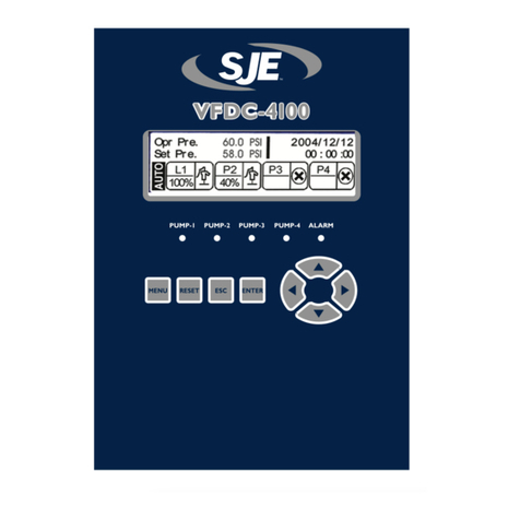
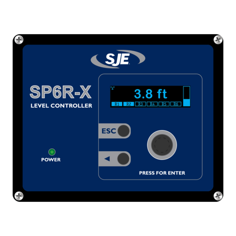
SJE VFDC-3000 User manual

VFDC-3000
CONSTANT PRESSURE CONTROLLER
User Manual
PUMP 1
PUMP 2
PUMP 3
ALARM
ESC
PRESS FOR ENTER
P1
P2
P3

TABLE OF CONTENTS
Warnings ............................................................................... 1
Introduction and Specifications ............................................. 2
Main Screen (Programming)................................................. 3
User Interface........................................................................ 3
Main Menu ............................................................................ 4
Controller Setpoints List........................................................ 5
Basic Settings ....................................................................... 6
Pump Settings....................................................................... 8
Advanced Settings ................................................................ 9
Controller Operation............................................................ 11
Alarms ................................................................................. 13
VFD and I/O Status Screens .............................................. 14
I/O Table ............................................................................. 15
Mounting Dimensions.......................................................... 16
Controller Dimensions......................................................... 17
Electrical Wiring Diagram.................................................... 18
SJE®VFDC-3000 Controller User Manual

WARNINGS
Failure to read and understand the information provided in this manual may result in personal injury
or death, damage to the product or product failure. Please read each section in its entirety and be
sure you understand the information provided in the section and related sections before attempting
any of the procedures or operations given.
Failure to follow these precautions could result in serious injury or death.
Keep these instructions with warranty after installation. This product must be
installed in accordance with National Electrical Code, ANSI/NFPA 70 so as to
prevent moisture from entering or accumulating within the controller housing.
ELECTRICAL SHOCK HAZARD
A qualified service person must install and service this product
according to applicable codes and electrical schematics.
Disconnect power prior to servicing any equipment.
EXPLOSION OR FIRE HAZARD
Do not use this product with flammable liquids. Do not install in
hazardous locations as defined by National Electrical Code,
ANSI/NFPA 70.
• Do not connect power to this equipment if it has been damaged or has
any missing parts.
• Do not install in areas with excessive or conductive dust, corrosive or
flammable gas, moisture or rain, excessive heat, regular impact shocks,
or excessive vibration.
SJE®1 VFDC-3000 Controller User Manual
Warning: Users must read this manual and understand controller operation before changing any settings.
Entering incorrect settings may result in damage to equipment.
If the controller was shipped pre-installed in a control panel, some default values may have been changed
at the factory in order to properly test the control panel operation. The user must adjust the settings to the
requirements of their particular installation
The user should always keep a record of the settings before making changes in case there is a need to
revert to previous settings. The user should also record all settings changed for use in programming a new
controller in case a replacement is ever needed.
Always thoroughly test controller operation in the installed configuration to verify user settings.

INTRODUCTION & SPECIFICATIONS
Congratulations and thank you for your purchase of the VFDC-3000 controller. This manual explains the
features and operations of the controller which was designed to operate up to 3 pumps in a constant pressure
application. The controller automatically adjusts pump speed and the on and off pump sequence in response
to changes in the system pressure. When used to control the system pressure, a 4-20mA pressure transmitter
is connected to the input. The controller features a rotary selector knob in addition to left shift and escape
push buttons for intuitive menu navigation and quick setting adjustments.
SJE®2VFDC-3000 Controller User Manual
GENERAL
• One, two or three pump constant pressure
controller
• Operates using 4-20mA pressure transmitter
• Rotary selector for menu navigation
• 2.7” blue OLED 64 x 256 pixel display
DIMENSIONS
• 7.2 x 5.3 x 2.0 inches (18.3 x 13.5 x 5.1 cm)
PUMP CONTROL AND PROTECTION
• Automatic pump sequencing
• Multiple sequencing configurations
• Automatic pump sequencing on VFD fault
• Pump run indication
• Variable speed
SYSTEM
• Alarm counts
• Number of starts for each pump
• Run time for each pump
ELECTRICAL SPECIFICATIONS
• 24 VDC Class 2 (19-28 VDC, 325mA max)
DEDICATED I/Os
• 4 digital inputs (low suction, high pressure,
low water, setpoint pressure 2)
• 6 relay outputs (configurable, 30 VAC/DC,
3A Max.)
• 1 analog input (4-20mA, 14 bit resolution,
non isolated)
MODBUS COMMUNICATION:
• Dedicated communication port for Mitsubishi
VFD control
ENVIRONMENT
• Operational temperature 32 to 122º F (0 to
50º C)
• Storage temperature -4 to 140º F (-20 to
60º C)
• Relative Humidity (RH) 5% to 95% (non-
condensing)
• Indoor rated - for indoor use or mounted
inside of an outdoor rated enclosure.

PROGRAMMING
MAIN SCREEN
The main screen provides the operator an overview of the system status including any active alarms.
SJE®3VFDC-3000 Controller User Manual
USER INTERFACE
Rotary Selector Knob
• Turn knob for scrolling
through menus or
adjusting values.
• Press knob for ENTER
or to save settings.
Red LED Indicates
an Active Alarm
Green LED Indicates
PUMP 1 Running
Green LED Indicates
PUMP 2 Running
Green LED Indicates
PUMP 3 Running
button returns to
previous menu screen,
and exits a parameter
edit screen without saving
changes.
ESC
Left Shift Button for shifting
the curser left and changing Value
Adjustment Scale.
PUMP 1
PUMP 2
PUMP 3
ALARM
ESC
PRESS FOR ENTER
P1
P2
P3
Lead pump indicator Pressure in psi
Communication
Status to
the VFDs
Alarm indication Message Bar Pump Speed (Hz)

SJE®4VFDC-3000 Controller User Manual
MAIN MENU
While in the Main Display screen, press the ENTER button to view the Main Menu. To view any setting,
simply scroll to the desired setting and press the ENTER button. While viewing any setting, change the
setting by using the knob to scroll and arrow button to select any digit desired, then press the ENTER button
to save the setting, or press ESC to leave the setting without saving. The ESC button can be used to back out
of any menu to the Main Display.
Counts and ETMs (Elapsed Time Meters)
The following screen displays the nine different Counts and ETMs that are tracked.
A CLEARING COUNT APPROVAL screen can be viewed by clicking the ENTER button when the desired
count is highlighted. Pump ETMs cannot be cleared.
Follow the on-screen directions, press ENTER for YES, ◄for NO.

SJE®5VFDC-3000 Controller User Manual
CONTROLLER SETPOINTS LIST
STATION NAME
START UP DATE
CONTROLLER REVISION
SETTING MIN MAX UNITS DEFAULT USER SETTING
BASIC SETTINGS
Setpoint Pressure 0.0 *1 PSI 60.0
Sleep Frequency 0.0 *2 Hz 35.0
Sleep Delay Time 0.0 999.9 Seconds 10.0
Minimum Frequency 0.0 *2 Hz 30.0
Maximum Frequency 0.0 65.0 Hz 60.0
Lead Pump Start Dierential Pressure *1 0.0 PSI -5.0
Lag Pump Start Dierential Pressure *1 0.0 PSI -7.0
Lag Pump Stop Dierential Pressure 0.0 *1 PSI 7.0
Alternation Alternate/P1 Lead/P2 Lead/P3 Lead Alternate
Alternation Time 1.0 999.9 Hours 24.0
Low Pressure Alarm 0.0 *1 PSI 15.0
Low Pressure Alarm Delay Time 0.0 999.9 Seconds 20.0
Low Pressure Alarm Reset Delay Time 0.0 999.9 Minutes 0.0
High Pressure Alarm 0.0 *1 PSI 75.0
Low Water Delay Time 0.0 999.9 Seconds 10.0
PUMP SETTINGS
Acceleration 0.0 3600.0 Seconds 3.0
Deceleration 0.0 3600.0 Seconds 3.0
Thrust Bearing Frequency 0.0 *2 Hz 0.0
Thrust Bearing Acceleration 0.0 3600.0 Seconds 2.0
Pump 1 Overload Amps 0.0 999.9 Amps *3
Pump 1 Motor Voltage 0.0 999.9 Volts *3
Pump 2 Overload Amps 0.0 999.9 Amps *3
Pump 2 Motor Voltage 0.0 999.9 Volts *3
Pump 3 Overload Amps 0.0 999.9 Amps *3
Pump 3 Motor Voltage 0.0 999.9 Volts *3
ADVANCED SETTINGS
Sensor Range 1.0 999.9 PSI 200.0
Sensor Oset -999.9 999.9 PSI 0.0
PID Proportional Term 0 999 70
PID Integral Term 0 999 35
PID Derivative Term 0 999 1
Setpoint Pressure 2 0.0 *1 PSI 40.0
Pipe Fill Frequency 0.0 *2 Hz 30.0
Pipe Fill Time 0.0 999.9 Seconds 0.0
Low Suction Delay Time 0.0 999.9 Seconds 10.0
Low Suction Reset AUTO/MANUAL AUTO
Low Suction Reset Delay Time 0.0 999.9 Seconds 10.0
Idle Prevention Exercise Schedule 0.0 999.9 Days 0.0
Pump 1 Jockey ENABLED/DISABLED DISABLED
Jockey Pump Stop Delay Time 0 999 Seconds 0
Number of Pumps 1 3 3
Maximum Pumps On 1 3 3
Relay 1 Function *4 GEN. ALARM
Relay 2 Function *4 HIGH PRESS
Relay 3 Function *4 LOW PRESS
Relay 4 Function *4 P1 RUN
Relay 5 Function *4 P2 RUN
Relay 6 Function *4 P3 RUN
VFD 1 Hand Speed 0.0 *2 Hz 45.0
VFD 2 Hand Speed 0.0 *2 Hz 45.0
VFD 3 Hand Speed 0.0 *2 Hz 45.0
Language ENGLISH/ESPAÑOL ENGLISH
*1 - Value based on “Sensor Range” setting
*2 - Value based on “Maximum Frequency” setting
*3 - Value based on output rating of variable frequency drive
*4 - Settings include: P1 Run, P2 Run, P3 Run, P1 Fault, P2 Fault, P3 Fault, High Press, Low Press, Low Suction, Low Water, General Alarm

BASIC SETTINGS
Setpoint Pressure
The Setpoint Pressure is the target pressure to be maintained at the pump discharge. It cannot exceed the
maximum range of the pressure transmitter.
Sleep Frequency
The Sleep Frequency setting should be set to the frequency at which the lead pump no longer builds pressure
when operating at or near the Setpoint Pressure. The lead VFD will enter the sleep mode when the output
frequency of the lead VFD drops below the Sleep Frequency for a period of time (Sleep Time). The sleep
function is suspended while the lag VFD is in operation.
Sleep Delay Time
Set the Sleep Delay Time to the amount of time that the lead VFD will wait before entering sleep mode after
the output frequency drops below the Sleep Frequency. Note: If the system cycles on and off too frequently,
try the following: increase the Sleep Delay Time, lower the Sleep Frequency, or increase the Lead Pump Start
Differential Pressure. A combination of changes of all three settings may be necessary. If the lead VFD does
not enter sleep mode when there is no flow of water in the system, the Sleep Frequency must be increased.
Minimum Frequency
The Minimum Frequency should be set to the minimum output frequency that the pumps should be allowed to
run. Contact your pump manufacturer to obtain the pump safe operation ranges.
Maximum Frequency
The Maximum Frequency should be set to the maximum output frequency that the pumps should be allowed
to run. Warning! Running above the motor nameplate frequency (50Hz or 60Hz) may cause damage to the
pump. Contact your pump and motor manufacturer for operation above the rated frequency on the nameplate.
Lead Pump Start Differential Pressure
The Lead Pump Start Differential Pressure is the amount of pressure drop from the Setpoint Pressure, at
which the lead VFD will wake from sleep and run to maintain the system pressure. The lead pump will start if
the pressure drops below the Setpoint Pressure less the Lead Pump Start Differential Pressure. Example: If
the Setpoint Pressure is 40 PSI and the Lead Pump Start Differential Pressure is -5 PSI, the lead pump will
start when the pressure drops below 35 PSI.
Lag Pump Start Differential Pressure
The Lag Pump Start Differential Pressure is the amount of pressure drop from Setpoint Pressure, while the
lead VFD is running full speed before a lag VFD is started. The lag VFD speed is controlled to maintain
pressure while in operation. The lead VFD will not be allowed to enter sleep mode while a lag VFD is running.
Lag Pump Stop Differential Pressure
The Lag Pump Stop Differential Pressure is the amount of pressure over the Setpoint Pressure before the lag
VFD is stopped.
Alternation
The Alternation setting can be adjusted to alternate the operation of Pump 1, 2 and 3 or to keep Pump 1, 2 or
3 as lead pump.
Alternation Time
The Alternation Time is the total accumulated run time of the current lead VFD, before the lead operation is
passed to the next available VFD in the sequence. Alternation Time is intended to even out the wear of the
pumps by transferring the lead operation after a set period of run time. Set to “0” to disable alternation.
Low Pressure Alarm
The Low Pressure Alarm is used to notify the user and stop the system if system pressure is unable to be
maintained at an allowable pressure. The Low Pressure Alarm can be set up to automatically reset after the
Low Pressure Alarm Reset Delay Time, or to require a manual reset by the user.
• Low Pressure Alarm
The Low Pressure Alarm setting should be set to the pressure below which the controller activates the Low
Pressure Alarm after the Low Pressure Alarm Delay Time.
• Low Pressure Alarm Delay Time
The Low Pressure Alarm Delay Time setting should be set to the amount of time that the system is below
the Low Pressure Alarm pressure, before the Low Pressure Alarm flag is set and pump operations are
SJE®6VFDC-3000 Controller User Manual

SJE®7VFDC-3000 Controller User Manual
suspended.
• Low Pressure Alarm Reset Delay Time
The Low Pressure Alarm Reset Delay Time setting should be set to the time after a Low Pressure Alarm
flag is set until the system automatically resets. Upon automatic reset, the Low Pressure Alarm flag is
cleared and normal operation of the controller resumes. If a manual reset of the Low Pressure Alarm is
desired, set the Low Pressure Alarm Reset Delay Time to “0.0”.
High Pressure Alarm
The High Pressure Alarm is used to notify the user and stop the pumps if the system pressure exceeds the
High Pressure Alarm setting. The High Pressure Alarm automatically resets after the system pressure drops
below the High Pressure Alarm setting.
Low Water Delay Time
The Low Water Delay Time setting should be set to the amount of time after a Low Water input is active,
before the Low Water flag is set and pump operations are suspended.

SJE®8VFDC-3000 Controller User Manual
Acceleration
Set the Acceleration setting to the rate at which the output frequency will increase during normal operation.
This rate is based on the time the VFD would take to accelerate from 0 Hz to 60 Hz. Example: If the pump is
required to accelerate from 30 Hz to 60 Hz in 1.5 seconds the Acceleration rate should be set to 3 seconds.
Deceleration
Set the Deceleration setting to the rate at which the output frequency will decrease during normal operation.
This rate is based on the time the VFD would take to decelerate from 60 Hz to 0 Hz. Example: If the pump is
required to decelerate from 60 Hz to 30Hz in 1.5 seconds the Deceleration rate should be set to 3 seconds.
Thrust Bearing Frequency
The Thrust Bearing Frequency should be set to the frequency at which the initial acceleration rate changes
to the acceleration rate of normal operation. This is typically used on submersible type pumps, where the
manufacturer requires a faster acceleration rate from a stop to the Thrust Bearing Frequency for proper thrust
bearing operation. Set to 0.0 to disable the thrust bearing function. Note: If the Pipe Fill function is used at a
lower frequency, it will take precedence over the thrust bearing function.
Thrust Bearing Acceleration
Set the Thrust Bearing Acceleration to the rate at which the pump should accelerate from a stop to the Thrust
Bearing Frequency. This is typically used on submersible type pumps, where the manufacturer requires a
faster acceleration rate for proper thrust bearing operation.
Pump 1~3 Overload Amps
The Pump 1~3 Overload Amps setting should be set to the full load amp rating of the pump for non-
submersible applications and to the service factor amps for submersible pumps.
Pump 1~3 Motor Voltage
The Pump 1~3 Motor Voltage setting should be set to the voltage on the nameplate of the pump. This setting
cannot exceed the incoming voltage measured at the control panel input power terminals.
PUMP SETTINGS

SJE®9VFDC-3000 Controller User Manual
Sensor Range
The Sensor Range setting is used to scale the 4-20mA signal of the pressure transmitter. The Sensor Range
should be set to the pressure at which the pressure transmitter is rated to output 20mA.
Sensor Offset
The Sensor Offset setting is used to offset the scale of the pressure transmitter to match actual pressure. The
Sensor Offset should be set to the difference of the trusted pressure reading and the current pressure reading
of the controller.
PID Proportional Term
The PID Proportional Term setting is intended to be adjusted by advanced users only. The PID Proportional
Term is used to adjust the reaction of the output frequency to changes in the system pressure. Increasing the
PID Proportional Term will allow the VFD to make larger corrections to the output frequency with differences
between the Setpoint Pressure and actual system pressure. Decreasing the PID Proportional Term will allow
the VFD to make smaller corrections to the output frequency with differences between the Setpoint Pressure
and actual system pressure.
PID Integral Term
The PID Integral Term setting is intended to be adjusted by advanced users only. The PID Integral Term is
used to adjust how quickly the output frequency reacts to changes in the system pressure. Decreasing the
PID Integral Term will allow the VFD to make quicker corrections to the output frequency with differences
between the Setpoint Pressure and actual system pressure. Increasing the PID Integral Term will allow the
VFD to make slower corrections to the output frequency with differences between the Setpoint Pressure and
actual system pressure.
PID Derivative Term
The PID Derivative Term setting is typically not used for pressure control applications and is intended to be
adjusted by advanced users only.
Setpoint Pressure 2
The Setpoint Pressure 2 is the target pressure to be maintained at the pump discharge when the Setpoint
Pressure 2 input is active on the controller. The setting cannot exceed the maximum range of the pressure
transmitter.
Pipe Fill Function
The Pipe Fill function is used to limit the maximum speed of the Lead VFD on startup to less than or equal to
the Pipe Fill Frequency for the Pipe Fill Time or until the Setpoint Pressure is reached, whichever comes first.
The Pipe Fill function can be disabled by setting Pipe Fill Time to “0.0”. Note: If the Thrust Bearing function is
used, the Pipe Fill function will take precedence if the Pipe Fill Frequency is set lower than the Thrust Bearing
Frequency.
• Pipe Fill Frequency
The Pipe Fill Frequency should be set to the lowest frequency at which the lead pump is able to
overcome unfilled pipe head conditions to fill the piping system.
• Pipe Fill Time
The Pipe Fill Time should be set to the time at which the lead pump is able to overcome unfilled pipe
head conditions to fill the piping system, while running at the Pipe Fill Frequency.
Low Suction Alarm
At any time during operation, if the low suction input is active for the “Low Suction Delay Time”, all VFD
operation shall immediately stop and a Low Suction Alarm is set. The system can be configured to
automatically restore operations after the input deactivates, or to require a manual reset.
•Low Suction Delay Time
The Low Suction Delay Time should be set so that false low suction conditions caused by an overly
sensitive pressure switch or the starting and stopping of adjacent pumping systems, do not interfere with
proper operation of the system.
• Low Suction Reset
Set the Low Suction Reset setting to AUTO to automatically restore normal operation of the system
upon the absence of a low suction input. In the MANUAL setting, the Low Suction Alarm remains active
until the ESC button is pressed and held for 2 seconds.
ADVANCED SETTINGS

• Low Suction Reset Delay Time
The Low Suction Reset Delay Time is used when the Low Suction Reset setting is in AUTO and should
be set to the amount of time after the low suction input deactivates until the system resumes normal
operation.
Idle Prevention
The Idle Prevention function shall run each pump at the “Minimum Frequency” for 30 seconds, if the VFD has
not run during the time set in the Idle Prevention Exercise Schedule setting.
• Idle Prevention Exercise Schedule
The Idle Prevention Exercise Schedule should be set to the maximum time a pump is allowed to set idle
before the pump is exercised by the controller. If the “Idle Prevention Exercise” setting is “0 days”, then
the Idle Prevention function is disabled.
Jockey Pump Operation
The Jockey Pump Function, when enabled, will run VFD 1 as Lead, on every pump cycle. There is no
alternation of the Lead pump (VFD 1). Only VFD 2 and VFD 3 will alternate as Lag 1 and Lag 2. If Lag 1 VFD
is called to run, VFD 2 and VFD 3 will start and run based on automatic alternation as in the normal operation.
» The Jockey Pump will shut down the “Jockey Pump Stop Delay” after the start of Lag 1 VFD.
» The Jockey Pump will not run again until Lag 2 and Lag 3 VFDs are OFF and the system pressure
drops below the “Start Lead diff Pressure”.
• Pump 1 Jockey
The Pump 1 Jockey setting should be set to ENABLED to allow pump 1 to function as a Jockey Pump or
set to DISABLED to not allow the Jockey Pump operation.
• Jockey Pump Stop Delay Time
The Jockey Pump Stop Delay Time setting is the time after the start of the lag 1 pump before the
Jockey Pump is shut down.
Number of Pumps
The Number of Pumps setting should be set to the number of pumps that the controller will operate.
Maximum Pumps On
The Maximum Pumps On setting is used to limit the number of pumps that can be running in automatic mode.
Relay 1~6 Function
The functions of Relay 1~6 are programmable.
The available functions are:
P1 Run, P2 Run, P3 Run, P1 Fault, P2 Fault, P3 Fault, High Press, Low Press, Low Suction, Low
Water, General Alarm.
These relays are normally open and are non-retentive during power loss.
VFD 1~3 Hand Speed
When the HAND/OFF/AUTO selector switch on the control panel is set to the HAND position, the VFD will run
the pump at a constant speed. The default frequency is 45 Hz.
Caution: Do not operate a pump in HAND mode for an extended time without close supervision. The pump
will not stop automatically on high pressure and will burst the pipes and cause damage.
Language
The Language setting selects the language displayed on the controller.
SJE®10 VFDC-3000 Controller User Manual

SJE®11 VFDC-3000 Controller User Manual
CONTROLLER OPERATION
Automatic Operation
The controller will monitor the status of the automatic switch input for each pump and will add or remove the
operation of each pump based on the status of this input. Only the pumps in automatic mode and without any
active fault conditions, shall be included in the Lead/Lag sequencing and operation.
Normal Operation (Only One Pump Needed)
The lead pump starts when system pressure drops the Start Lead Differential Pressure below the Setpoint
Pressure. The lead pump runs, and its speed is controlled via PID control. If the lead pump’s speed falls
below the Sleep Frequency for the Sleep Delay Time, the lead pump’s operation shall be suspended.
Normal Operation (Two Pumps Needed)
The lead pump starts when system pressure drops the Start Lead Differential Pressure below the Setpoint
Pressure. The lead pump runs, and its speed is controlled via PID control. If the lead pump cannot keep up
with the demand for water, running at the Maximum Frequency and the system pressure drops to the Start
Lag Differential Pressure below the Setpoint Pressure, the lead pump shall be held at Maximum Frequency
and the speed of the lag 1 pump, which is the next pump in the sequence after the lead pump, shall have its
speed controlled via PID control. If the system pressure exceeds the Stop Lag Differential Pressure above
the Setpoint Pressure, and the lag 1 pump is operating at the Minimum Frequency, the lag 1 pump output
shall be suspended, and the lead pump speed is controlled via PID control. If the lead pump’s speed falls
below the Sleep Frequency for the Sleep Delay Time, the lead pump’s operation shall be suspended.
Normal Operation (Three Pumps Needed)
The lead pump starts when system pressure drops the Start Lead Differential Pressure below the Setpoint
Pressure. The lead pump runs, and its speed is controlled via PID control. If the lead pump running at the
Maximum Frequency cannot keep up with the demand for water and the system pressure drops to the Start
Lag Differential Pressure below the Setpoint Pressure, the lead pump shall be held at Maximum Frequency
and the speed of the lag 1 pump, which is the next pump in the sequence after the lead pump, shall have
its speed controlled via PID control. If the lead pump and lag 1 pump cannot keep up with the demand for
water and the system pressure drops to the Start Lag Diff Pressure below the Setpoint Pressure, the next
pump in the sequence after the lag 1 pump, shall have its speed controlled via PID control. If the system
pressure exceeds the Stop Lag Differential Pressure above the Setpoint Pressure, and the lag 2 pump is
operating at the Minimum Frequency, the lag 2 pump output shall be suspended, and the lag 1 pump speed
is controlled via PID control. If the system pressure exceeds the Stop Lag Differential Pressure above the
Setpoint Pressure, and the lag 1 pump is operating at the Minimum Frequency, the lag 1 pump output shall
be suspended, and the lead pump speed is controlled via PID control. If the lead pump speed falls below the
Sleep Frequency for the Sleep Delay Time, the lead pump output shall be suspended.
Pump Sequencing
Current Pump Assignment Next Pump Assignment
Lead Lag 1 Lag 2 Lead Lag 1 Lag 2
Pump 1 Pump 2 Pump 3 Pump 2 Pump 3 Pump 1
Pump 2 Pump 3 Pump 1 Pump 3 Pump 1 Pump 2
Pump 3 Pump 1 Pump 2 Pump 1 Pump 2 Pump 3

SJE®12 VFDC-3000 Controller User Manual
Low Pressure Alarm Condition
At any time during operation, if the system pressure drops below the Low Pressure Alarm level for the Low
Pressure Alarm Delay Time, all pump operation shall immediately stop, and a Low Pressure Alarm ag shall
be set. The Low Pressure Alarm condition shall remain until the Low Pressure Alarm Reset Delay Time has
expired. If the Low Pressure Alarm Reset Delay Time is set to “0 min”, the Low Pressure Alarm condition
must be manually reset by pressing and holding the ESC button for 2 seconds.
High Pressure Alarm Condition
At any time during operation, if the system pressure increases above the High Pressure Alarm level, all
pump operation shall immediately stop, and a High Pressure Alarm ag shall be set. When the system
pressure drops below the High Pressure Alarm level and a delay of 10 seconds has elapsed, the High
Pressure Alarm ag shall cease, and normal operation shall resume.
Low Suction Pressure Alarm Condition
At any time during operation, if the Low Suction Pressure input is active for the Low Suction Pressure Delay
Time, all pump operation shall immediately stop, and a Low Suction Pressure Alarm ag shall be set. When
the Low Suction Pressure input deactivates, the Low Suction Pressure Alarm ag shall cease, and normal
operation shall resume.
Low Water Alarm Condition
At any time during operation, if the Low Water Alarm input is active, all pump operation shall immediately
stop, and a Low Water Alarm ag shall be set. When the Low Water Alarm input deactivates, the Low Water
Alarm ag shall cease, and normal operation shall resume.
Pressure Sensor Open Circuit Alarm
At any time during operation, if the controller senses an open circuit on the pressure transmitter, all pump
operation shall immediately stop, and a Pressure Sensor Open Circuit Alarm ag shall be set. When the
controller senses a normal pressure transmitter signal, the Pressure Sensor Open Circuit Alarm ag shall
cease, and normal operation shall resume.
Pressure Sensor Short Circuit Alarm
At any time during operation, if the controller senses a short circuit on the pressure transmitter, all pump
operation shall immediately stop, and a Pressure Sensor Short Circuit Alarm ag shall be set. When the
controller senses a normal pressure transmitter signal, the Pressure Sensor Short Circuit Alarm ag shall
cease, and normal operation shall resume.
Pump 1-3 Fault Alarm
At any time during operation, if a fault is found on any of the VFDs, a Pump Fault Alarm ag is set for the
corresponding pump and the faulted VFD is removed from the alternation sequence and operation. If the
fault condition is repaired and the VFD is reset, the VFD is returned to the alternation sequence and normal
operation shall resume.
Pump 1-3 Comm Fail Alarm
At any time during operation, if a communication failure is found for any of the VFDs, a Pump Comm Fail
Alarm ag is set for the corresponding pump and the VFD is removed from the alternation sequence and
operation. If the communication is restored, the VFD is returned to the alternation sequence and normal
operation shall resume.

SJE®13 VFDC-3000 Controller User Manual
ALARM TEXT DEFINITION FIX
LOW PRESSURE
ALARM
The system pressure is below the low
pressure alarm setting.
Check pump rotation, check pump
discharge plumbing, check pump intake.
HIGH PRESSURE
ALARM
The system pressure is above the
high pressure alarm setting or the high
pressure input is active.
Check pump HAND/OFF/AUTO
switches.
LOW SUCTION
PRESSURE ALARM The low suction pressure input is active. Check pump intake, check suction
pressure switch, check water supply.
LOW WATER ALARM The low water alarm input is active. Check level switch, check water supply.
PRESSURE SENSOR
OPEN CIRCUIT
The controller is seeing an open circuit
on the pressure transmitter input.
Check pressure transmitter cable, check
pressure transmitter connector, replace
defective pressure transmitter.
PRESSURE SENSOR
SHORT CIRCUIT
The controller is seeing a short circuit
on the pressure transmitter input.
Check pressure transmitter cable, check
pressure transmitter connector, replace
defective pressure transmitter.
PUMP 1 FAULT There is an active fault condition on the
pump 1 VFD.
Check active fault of pump 1 VFD, repair
fault condition of pump 1 VFD.
PUMP 2 FAULT There is an active fault condition on the
pump 2 VFD.
Check active fault of pump 2 VFD, repair
fault condition of pump 2 VFD.
PUMP 3 FAULT There is an active fault condition on the
pump 3 VFD.
Check active fault of pump 3 VFD, repair
fault condition of pump 3 VFD.
PUMP 1 COMM FAIL The controller is unable to communicate
with the pump 1 VFD.
Check communication cable from
controller to pump 1 VFD. Check pump 1
VFD communication parameters.
PUMP 2 COMM FAIL The controller is unable to communicate
with the pump 2 VFD.
Check communication cable from
controller to pump 2 VFD. Check pump 2
VFD communication parameters.
PUMP 3 COMM FAIL The controller is unable to communicate
with the pump 3 VFD.
Check communication cable from
controller to pump 3 VFD. Check pump 3
VFD communication parameters.
ALARMS

SJE®14 VFDC-3000 Controller User Manual
VFD and I/O STATUS SCREENS
DIGITAL INPUT STATUS
This screen shows the status of all four digital (discrete) inputs. Each input is shown as either open circuit
(“Open”) or closed circuit (“Closed”). This can be used for troubleshooting to make sure the controller is
seeing changes in input states.
RELAY OUTPUT STATUS
This screen shows the status of all six relay outputs. Each relay output is shown as either open circuit (“Off”)
or closed circuit (“On”). This can be used for troubleshooting to make sure the controller is turning on and off
the output relays as expected.
ANALOG I/O STATUS
This screen shows the current in mA of the analog input (A IN) and analog output (A OUT). This can be used
for troubleshooting to make sure the 4-20mA signals are behaving as expected.
VFD STATUS
This screen shows the output frequency and output current of each VFD. This can be used for troubleshooting
to make sure motor current is as expected.

SJE®15 VFDC-3000 Controller User Manual
I/O TABLE
J1 POWER AND COMMUNICATIONS
PIN NAME DESCRIPTION
1 N/C - NO CONNECTION -
2 N/C - NO CONNECTION -
3 0V RETURN FOR +24 VDC SUPPLY
4 +24 VDC 19 - 28 VDC SUPPLY
5 D+ VFD COMM (RS-485) - MODBUS
6 D- VFD COMM (RS-485) - MODBUS
7 SHIELD
8 A OUT 4-20mA LOOP, POWER SUPPLIED
9 AO COM 4-20mA LOOP RETURN
10 N/C - NO CONNECTION -
11 GND PROTECTIVE EARTH GROUND
12 GND PROTECTIVE EARTH GROUND
J2 RELAY OUTPUTS
PIN NAME DESCRIPTION
1RELAY 1 CONFIGURABLE RELAY 1
2
3RELAY 2 CONFIGURABLE RELAY 2
4
5RELAY 3 CONFIGURABLE RELAY 3
6
7RELAY 4 CONFIGURABLE RELAY 4
8
9RELAY 5 CONFIGURABLE RELAY 5
10
11 RELAY 6 CONFIGURABLE RELAY 6
12
J3 DIGITAL/ANALOG INPUTS
PIN NAME DESCRIPTION
1 COM INPUT COMMON RETURN
2LOW SUCTION LOW SUCTION INPUT
3HIGHPRESSURE HIGH PRESSURE INPUT
4LOW WATER LOW WATER INPUT
5SETPOINT 2 SETPOINT PRESSURE 2 INPUT
6N/C - NO CONNECTION -
7N/C - NO CONNECTION -
8N/C - NO CONNECTION -
9N/C - NO CONNECTION -
10 N/C - NO CONNECTION -
11 N/C - NO CONNECTION -
12 N/C - NO CONNECTION -
13 SHIELD
14 NC - NO CONNECTION -
15 PRESSURE 4 - 20mA LOOP INPUT
16 +24 VDC OUT PRESS TRANSMITTER SUPPLY
All Digital Input functions are activated upon a
contact closure to the Input Common Return (COM)
terminal.
Note:
Pins J1-3, J1-7, J1-11, J1-12, J3-1, J3-13 and J3-14
are all internally connected and should be wired to
Protective Earth Ground at terminal J1-11 or J1-12.

SJE®16 VFDC-3000 Controller User Manual
MOUNTING DIMENSIONS
Not to scale. Do not use as a template.
TUO
TUC
6.80”
5.30”
6.50”
5.00”

SJE®17 VFDC-3000 Controller User Manual
CONTROLLER DIMENSIONS
7.2”
5.7” 5.3”
PUMP 1
PUMP 2
PUMP 3
ALARM
ESC
PRESS FOR ENTER
6.5”
5.0”
2.5”
6.8”
P1
P2
P3

SJE®18 VFDC-3000 Controller User Manual
ELECTRICAL WIRING DIAGRAM
1 2 3 4 5 6 7 8
HOA
XOO
XOX
23
24
13
14
HOA
XOO
XOX
23
24
13
14
HOA
XOO
XOX
23
24
13
14
1
2
3
4
5
6
7
8
9
10
11
12
1
2
3
4
5
1 2 3 GTB1
TB2
TB2
TB2
TB3
PRESSURE
SENSOR
4-20mA
LOW
SUCTION
PRESSURE
SWITCH
Table of contents
Languages:
Other SJE Controllers manuals
Popular Controllers manuals by other brands
Metso
Metso Jamesbury Valv-Powr Value-Line D VPVL Series Installation maintenance and operating instructions
Monicon Instruments
Monicon Instruments AVR-15 user manual
Rockwell Automation
Rockwell Automation Allen-Bradley PowerFlex 70 quick start
GoBright
GoBright Desk Connect User manual & Safety instructions

Distech Controls
Distech Controls ECB-VAV UUKL installation guide
Smartgen
Smartgen HAT160 user manual
