Ski-Daddler 5811-0000 User manual

.
MODELS
5811
-0000,
-0100
5812-0
000
I
-0200
PA
TS AND SERVICE
MANUAL
AMERICAN
MACH
INE
&
FDUNDRY
CDMPANY
CONSUMER
PRODUCTS
SALES
DIVISION
PARTS
&
SERV
I
CE
DEPARTMENT
Whiteford
Road
,
York.
Pennsy
lv
an
ia
17402.
Area
Code
717
848-
11
77
PART
NO
.
37949
TABLE
OF
CONTENTS
Page
WARRANTY
SER
VICE
..............
2
TABLE
OF
CONTENTS
.............
3
CHASSIS
..........................
4
To
R
epl
ace
Top
Shroud
...........
4
To
Repa
ir
Top
Shroud
............
4
To
Replace
Fuel
Tank
............
4
STEERING
........................
6
Ski
Alignment
.
..................
6
POWER
TRAIN
...................
, 7
To
Remove
Torque
Converter
Belt
............
.
...............
7
To
Remove
Driving
Clutch
Bell
Housing
.........................
7
To
Remove
Chain
Housing
and
Driven
Clutch
....................
7
To
Replace
Drive
Chain
..........
8
TRACK
OROUP
....................
9
To
Remove
Drive
Track
..........
9
Track
Alignment
.................
10
Brake
Adjustment
................
11
To
Remove
Boggie
Wheels,
Bog
-
gie
Springs,
and
Boggie
Wheel
Bearings
.....•..................
11
To
Remove
Idler
Sprockets
........
11
Bearing
Cover
Replacement
.......
11
To
Remove
Drive
Sprockets
.......
11
CARBURETOR
MODEL
5811
..
0
••••••
12
CARB
URETOR
MODEL
5812
.........
12
ELECTRICAL
INFORMA
TION
.......
13
Head
Lamp
......................
13
Tail
Lamp
......................
13
REPAIRMAN'S
REFERENCE
WIRING
DIAGRAM
..............•..........
14
LUBRICATION
INSTRUCTIONS
......
15
-3-
Page
FUEL
MIXTURE
•..................
15
FUEL
MIXTURE
INSTR
UCTIONS
....
15
CHASSIS.
0
••••••••••••••••••••••••
16
CHASSIS
PAR
TS
LIST
..............
17
SKIS
AND
STEERING.
0
•••••••••••••
18
SKIS
AND
STEERING
PAR
TS
LIST
...
19
ENGINE,
ELECTRICAL
AND
FUEL
ELEMENTS
........
0
••••••••••••••
20
ENGINE,
ELECTRICAL,
AND
FUEL
ELEMENTS
PAR
TS
LIST
.....
21
DRIVE
TRACK
............
...•....
22
DRIVE
TRACK
PARTS
LIST
........
23
CARBURETOR
MODEL
5811 -
HL
20914
.........................
24
CARB
URETOR
MODEL
5811
PARTS
LIST
......................
24
CARB
URETOR
MODEL
5811 -
HL
210A
..........................
25
CARB
URETOR
MODEL
5811
PAR
TS
LIST
...........
..
.........
25
CARB
URETOR
MODEL
5812
-
HR
2A
...
.
.......................
26
CARBURETOR
MODEL
5812
PAR
TS
LIST
......................
26
CHASSIS
TO
R
EPL
ACE
TOP
SHROUD
1.
Remove
right
and
left
half
end
caps
from
the
aluminum
trim
s
tr
ip
by
removing
two
screws
and
two
lock
nuts.
2.
Remove
rubber
bumper
s
trip
from
trim
strip
around
top
shroud
by
prying
out
with
a
screw
dr
i
ver
.
3.
Remove
pop
rivets
by
drilling
them
out.
4.
Remove
aluminum
trim
strip.
5.
Remove
bracket
holding
st
ee
ring
col
-
umn
to
the
top
sh
roud
by
removing
two
screws,
t\\"O
nuts
and
a
holding
plate
.
Remove
fasteners
from
inside
storage
compartment
on
top
shroud
.
6.
Remove
gas
cap
and
sup
port
angle
wh
ic
h
ho
lds
the
fuel
intake
to the
top
shroud
.
To
release
the
support
an
gle
remove
one
scre\v
and
one
nut
from
the
top
shroud
.
7.
Disconnect
wiring
loom
at
connector
plug
.
8.
Remove
light
switch
by
removing
two
nuts
from
the
outside
of
the
s\v
itch
.
Then
push
switch
out.
9.
Remove
ignition
s
witch
by
removing
nut
on
the
backs
ide of
the
s
witch
.
Then
push
switch
out.
10.
Remove
wire
holding
clips
from
the
edge
of the
access
hole
on
the
top
shroud.
11.
Remove
headlamp
assembly
from
the
front
of the
top
shroud
by
removing
two s
crews
.
and two
nuts.
12
.
Use
reverse
procedure
from
that
s
tated
above
to
install
new
top
shroud.
13
.
Use
either
a
pop
rivet
gun
and
pop
rivets
or
fla
t
head
screws
and
lock
nuts
to
se
cure
new
top
shroud.
If
flat
head
screws
are
u
sed,
work
thro
ugh
the
acces
s
opening
.
14
.
If
you
have
difficulty
in
replacing
rub-
berbumper
strip,
use
a
small
amount
of
trim
cement
to
keep
it
in
place.
TO
REPAIR
TOP
SHROUD
If
the
top
shroud
is
fractured
or
punctured,
repair
with
polyester
resin
and
fibre
gl
ass
cloth.
See
CHASSIS
parts
list
for
pa
int
in-
format
ion.
NOTE:
The
repair
materials
are
not
sup-
plied
or
kept
in
stock
by
the
manufacturer
.
However,
they
can
be
purchased
locally
through
auto
part
s
or
marine
supply
com
-
panies.
TO
REPLACE
FUEL
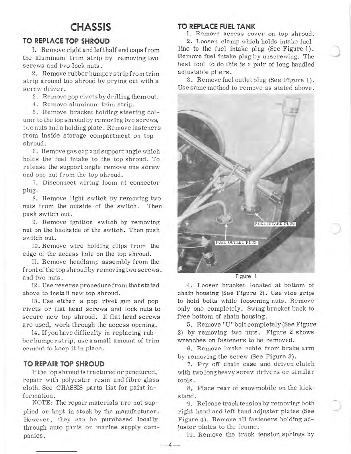
TANK
1.
Remove
access
cover
on
top
shroud
.
2.
Loosen
clamp
which
hol
ds
intake
fuel
line
to the fuel intake
plug
(See
Figure
1) .
Remove
fuel
intake
plug
by
unscrewing
.
The
be
st
tool
to
do
this
is
a
pair
of
long
handled
adjustable
pliers
.
3.
Remove
fuel
outlet
plug
(See
Figure
1).
Use
s
ame
method
to
remove
as
stated
abo
ve .
F
igure
1
4.
Loo
s
en
bracket
located
at
bottom
of
chain
housing
(See
Figure
2).
Use
vice
grips
to
hold
bolt
s
while
loosening
nuts.
Remove
only
one
completely
.
Swing
bracke
t
back
to
free
bottom
of
chain
hous
ing
.
5.
Remove
"U"bolt
completely
(See
Figure
2)
by
removing
two
nuts.
Figure
2
shows
wrenches
on
fasteners
to
be
removed.
6.
Remove
brake
cabl
e
from
brake
arm
by
removing
the
screw
(See
Figure
3) .
7.
Pry
off
chain
case
and
driven
clutch
with
two
long
heavy
screw
drive
rs
or
similar
tools.
8.
Place
rear
of
snowmobile
on
the
kick
-
stand.
9.
Release
track
tension
by
removing
both
right
hand
and
left
hand
adjuster
pla
te
s (See
Figure
4).
Remove
all
fas
teners
holding
a
d-
juster
plates
to
the
frame.
.
10.
Remove
the
track
tensiol!-fip~ing
s
by
-4-
)

Figure
2
c
Figure
3
Figure
4
-5-
pushing
the
extended
top
end
toward
the
center
and
pulling
down.
Use
same
procedure
on
both
sides
(See
Figure
5).
Now
the
rear
support
arms
and
idler
sprockets
can
be
re
-
moved.
Figure
5
11.
Tip
snowmobile
up
on
its
right
side.
12.
Remove
the
three
boggie
assemblies
by
removing
a
bolt
and
a
washer
from
each
end
of
the
boggie
wheel
support
shaft.
Figure
6
shows
bolt
and
washer
to
be
removed.
13. Now
the
only
thing
holding
the
track
in
place
is
the
driving
sprockets
and
drive
shaft.
To
remove:
a.
With
a
screw
driver
carefully
pry
rubber
oil
seal
from
the
bearing
retainer
Figure
6

on
the
drive
shaft
(See
Figure
7)
on
both
right
and
left
hand
sides.
b .
Figure
8
shows
the
drive
shaft
and
driving
sprockets
being
removed.
Pull
shaft
towards
the
side
which
has
the
chain
housing
removed.
This
will
free
the
drive
shaft
and
sprockets
for
removal.
Figure 7
Figure 8
NOTE:
When
replacing
drive
sprockets
and
drive
shaft,
add
one
-two
ounces
of
oil
to
center
of
shaft.
Also
check
oil
level
in
chain
housing
after
it
is
reinstalled.
The
oil
level
shouldbe
approximately
2~
inches
deep
in
the
chain
housing
(approximately
5
ounces).
Do
not
overfill
as
overfilling
can
cause
leakage
at
vent
hole
and
possibly
get
oil
on
torque
con-
verter
belt.
14
.
Figure
9
shows
screws
and
nuts
to
be
removed
to
remove
fuel
tank
retainer
plate.
15.
Remove
retainer
plate
(See
Figure
10).
16.
Remove
bearing
retainer
which
holds
the
drive
sha
ftby
removing
four
nuts
and
bolts
(SeeFigure
8).RerrlOve
cha
in
case
bolt
on
the
opposite
side
of
theBearingR
etaine
r.
17.
Remove
fuel
tank.
18.
Reassemble
in
opposite
order
as
stated
Figure
9
Figure
10
above.
19.
During
reassembly
follow
instructions
un
d e r TRACK
TENSION
ADJUSTMENT,
TRACK
ALIGNMENT
AND
BRAKE
ADJUST
-
MENT.
STEERING
Skis
should
be
properly
aligned
so
they
are
parallel
to
each
other
and
parallel
with
the
drive
track
when
the
steering
handle
is
in
the
str
aight
ahead
position.
Figure
II
shows
skis
properly
aligned.
Measure
the
distance
be
-
tween
the
skis
at
the
front
and
at
the
rear.
The
distances
should
be
equal.
Figure
llshows
the
front
measuring
points.
SKI
ALIGNMENT
1.
Center
steering
handle,
check
to
see
that
right
hand
ski
is
parallel
with
the
drive
track.
2.
If
right
hand
ski
is
not
parallel
to
drive
track
adjust
drag
link.
If
a
large
amount
of
adjustment
appears
necessary,
remove
spin
-
dle
arm
retaining
bolt
with
zerk
fitting
(See
Figure
12).
Remove
the
spindl
e
arm
from
the
spindle.
3.
Align
right
hand
ski
so
that
it
is
parallel
-6
-
)
..

I
}(
.
'-
FRONT
MEASURING
POINTS
Figure
11
Figure
12
with
track
and
replace
spindle
arm
on
the
spindle
making
sure
that
the
splines
are
align
-
ed
and
securely
tighten
retaining
bolt.
4.
Measure
skis
front
and
rear
making
sure
that
both
skis
are
in
alignment.
If
the
skis
are
not
in
alignment
with
each
other,
ad-
just
tie
rod
by
loosening
the
lock
nuts
and
rotating
tie
rod.
POWER TRAIN
TO REMOVE TORQUE CONVERTER
BELT
Remove
the
belt
guard
and
use
a
screw
driver
or
similar
tool
to
pry
driven
sheaves
apart
as
shown
in
Figure
13
.
Pull
the
drive
belt
down
into
the
driven
sheave
halves.
This
will
make
enough
slack
in
the
drive
belt
to
easily
pull
it
up
over
the
driving
clutch.
Re
-
move
other
end
from
driven
clutch.
Replace
in
reverse
order.
Mter
replacing
the
belt
check
the
b
elt
tension
.
There
should
be
lOi
inches
between
the
center
of
the
driving
clutch
and
the
driven
clutch
(See
Figure
13).
If
ad
-
justment
is
neces
sary,
loosen
nuts
securing
engine
and
slide
it
backward.
The
engine
can
be
moved
backwards
a
total
of
i
inches.
Figure 13
TO REMOVE
DRIVING
CLUTCH
BELL
HOUSING
1.
Remove
the
bolt
assembly
from
the
out-
side
of
the
bell
clutch
housing
(See
Figure
13).
2.
Hold
the
two
halves
of
the
clutch
to-
getherwhen
removing
the
bell
clutch
housing.
IMPORTANT
:
Remove
housing
with
care
to
preven
t
any
possible
damage
to
the
clutch
assembly
.
3.
When
replacing
bell
clutch
housing
make
sure
the
weight
s
fit
into
the
notches
on
the
outer
sheave.
4.
Lubricate
bearing
and
spring
retainer
before
reassembly
.
TO REMOVE
CHAIN
HOUSING
AND
DRIVEN CLUTCH
1.
Remove
drive
belt
as
stated
above.
2.
Loosen
bracket
at
bottom
of
the
chain
housing
(See
Figure
14) .
Use
vice
grips
to
hold
bolts
while
loosening
nuts.
Remove
only
one
completely.
S\\'ing
bracket
back
to
free
bottom
of
chain
housing.
3.
Remove
"U"bolt
completely
(See
Figure
14)
by
removing
two
nuts
.
Figure
14
shows
wrenches
onfasteners
to
be
loosened
and
re-
moved.
- 7 -
Figure
14
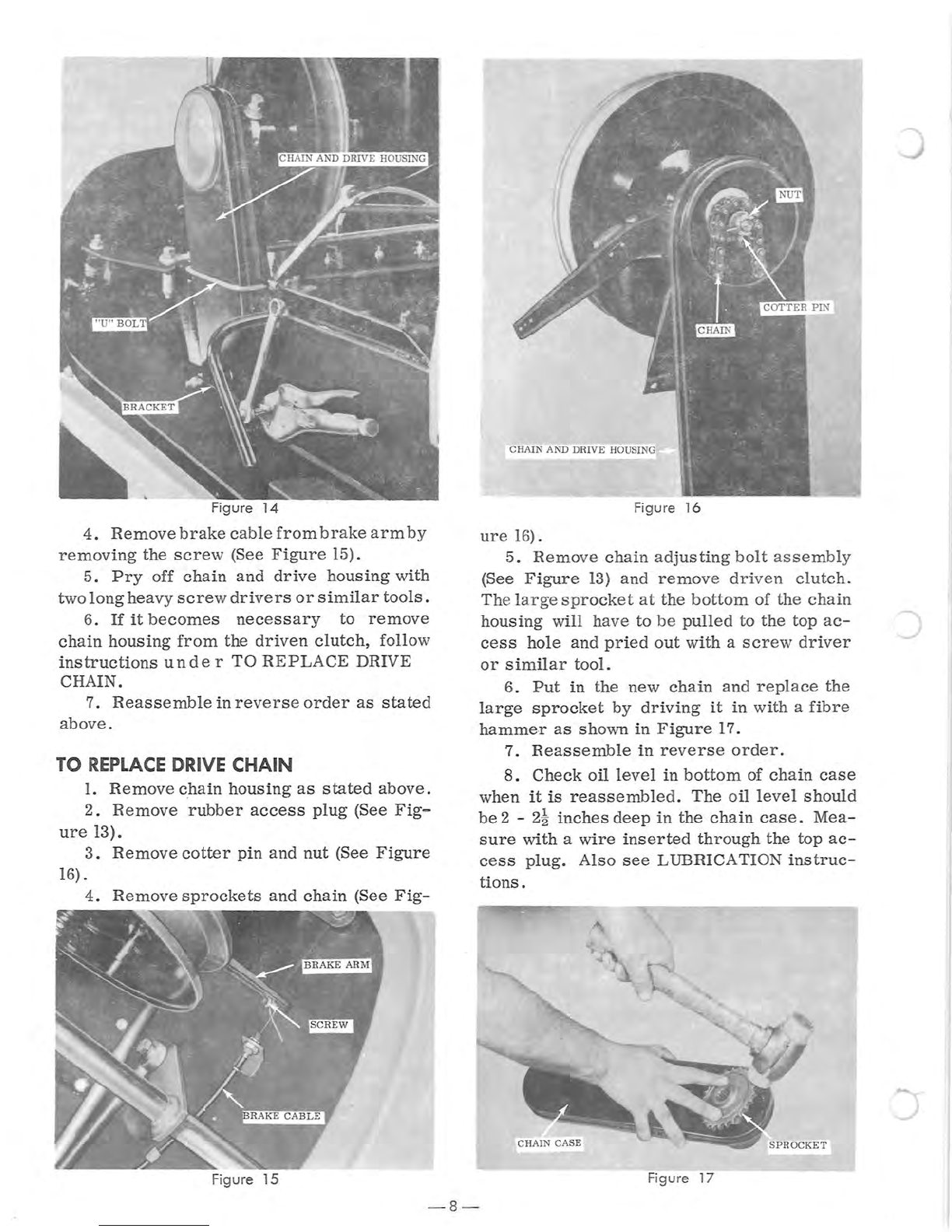
4.
Remove
brake
cable
from
brake
armby
removing
the
screw
(See
Figure
15).
5.
Pry
off
chain
and
drive
housing
with
two
long
heavy
screw
drivers
or
similar
tools.
6.
If
it
becomes
necessary
to
remove
chain
housing
from
the
driven
clutch,
follow
instructions
unde
r
TO
REPLACE
DRIVE
CHAIN.
7.
Reassemble
in
reverse
order
as
stated
above.
TO
REPLACE
DRIVE
CHAIN
1.
Remove
chain
housing
as
stated
above.
2.
Remove
rubber
access
plug
(See
Fig-
ure
13).
3.
Remove
cotter
pin
and
nut
(See
Figure
16)
.
4.
Remove
sprockets
and
chain
(See
Fig-
Fi
gure
15
CHAIN AND DRIVE HOUSING
Fi
gu
re
16
ure
16
).
5.
Remo
ve
chai
n
adjus
ting
bo
lt
as
sem
bly
(See
Figure
13)
and
remo
ve d
riv
en
c
lu
tch.
Th
e
la
r ge
sp
rocket
at
the
bottom
of
t
he
ch
ain
housing
will
ha
ve
to
be
pulled
to
the
top
ac-
cess
hole
and
pried
out
with
a
scr
ew
driver
or
similar
tool.
6.
Put
in
t
he
new
chain
and
repl
a
ce
the
large
sprocket
by
driving
it
in
wit
h a
fibre
hammer
as
shown
in
Figure
17.
7.
Reassemble
in
reverse
order.
8.
Check
oil
level
in
bottom
of
chain
case
when
it
is
reassembled.
The
oil
level
should
be
2 - 2!
inches
deep
in
the
chain
case.
Mea
-
sure
with
a
wire
inserted
through
the
top
ac-
cess
plug.
Also
see
LUBRICATION
instruc
-
tions.
Figure 17
- 8 -
)

c
-r
'--
TRACK GROUP
TO
REMOVE
DRIVE
TRACK
1.
Loosen
bracket
located
at
bottom
of
chain
housing
(See
Figure
18).
Use
vice
grips
to
hold
bolts
while
loosening
nuts.
Remove
only
one
completely.
Swing
bracket
back
to
free
bottom
of
chain
housing.
2.
Remove
"U"bolt
completely
(See
Figure
18)
by
removing
two
nuts.
Figur
e
18
shows
wrenches
on
fasteners
to
be
loosened
and
re-
moved.
Figure 18
3.
Remove
brake
cable
from
brake
arm
by
removing
the
screw
(See
Figure
19)
.
4.
Pry
off
cha
in
and
drive
hous
ing
\\lith two
long
heavy
screw
drivers
or
similar
tools.
5.
Place
rear
of
snowmobile
on
the
kick-
stand.
Figure 19
- 9 -
6.
Release
track
tension
by
removing
both
right
hand
and
left
hand
adjuster
plates
(See
Figure
20).
Remove
all
fasteners
holding
ad
-
juster
plates
to
the
frame.
7.
Remove
the
track
tension
springs
by
pushing
the
extended
top
end
toward
center
pulling
down.
Use
same
procedure
on
both
sides
(See
Figure
21). Now
the
rear
support
arms
and
idler
sprockets
can
be
removed.
8.
Lay
snowmobile
on
its
right
side.
9.
Remove
the
three
boggie
assemblies
by
removing
a
bolt
and
a wa
sher
from
each
end
of
the
b
rt
shaft.
F
~.;;..;;..;-,;
Figure
20
Figure
21
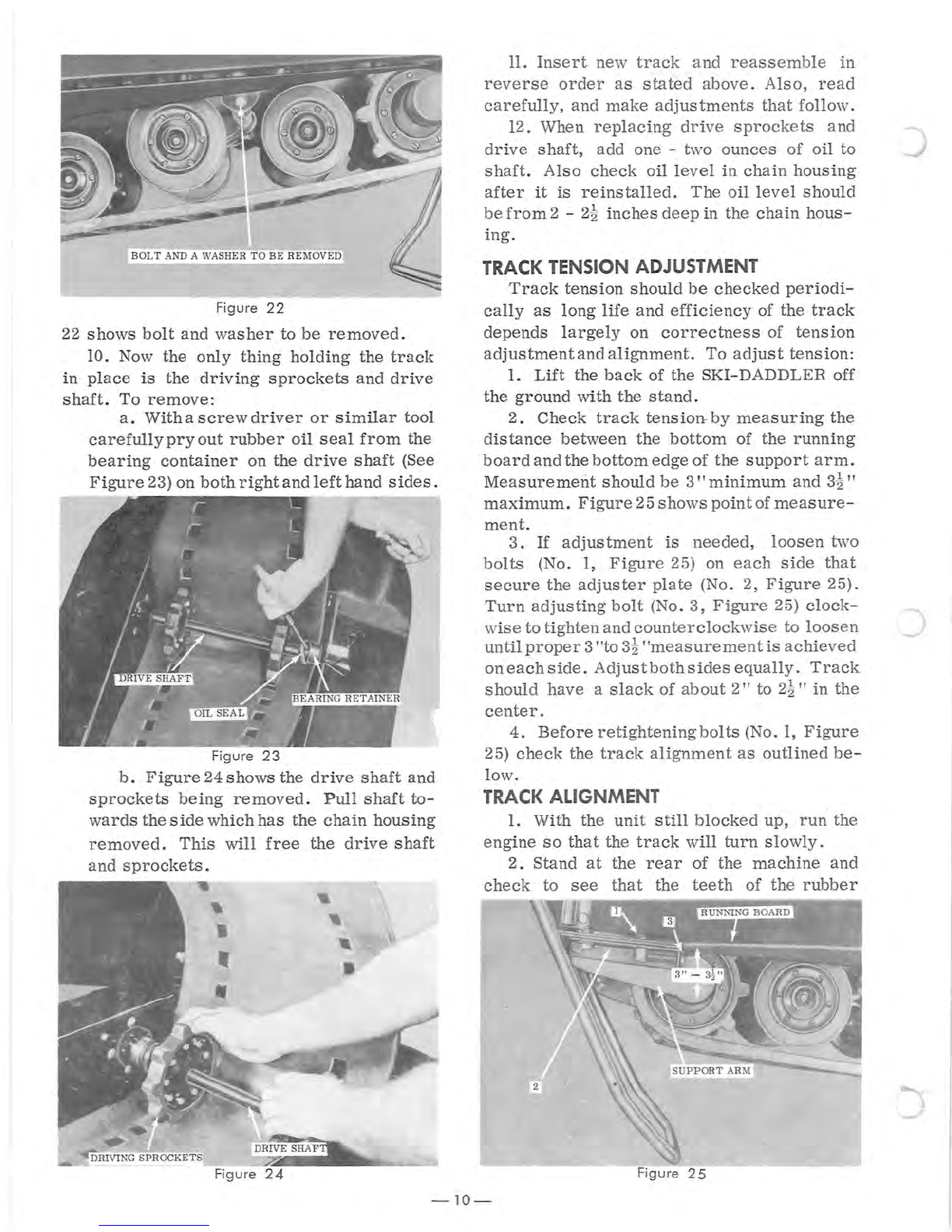
BOL
T AND A WASHER
TO
BE
REMOVED
Figure
22
22
shows
bolt
and
washer
to
be
removed.
10. Now
the
only
thing
holding
the
track
in
place
is
the
driving
sprockets
and
drive
shaft.
To
remove
:
a.
With
a
screwdriver
or
similar
tool
carefully
pry
out
rubber
oil
seal
from
the
bearing
container
on
the
drive
shaft
(See
Figure
23)
on
both
right
and
left
hand
sides.
Figure
23
b.
Figure
24 shows the
drive
shaft
and
sprockets
being
removed.
Pull
shaft
to-
wards
the
side
which
has
the
chain
housing
removed.
This
will
free
the
drive
shaft
and
sprockets.
•
• ,
,
11.
Insert
new
track
and
reassemble
in
reverse
order
as
stated
above.
Also,
read
carefully,
and
make
adjustments
that
follow.
12. When
replacing
drive
sprockets
and
drive
shaft,
add
one -two
ounces
of
oil
to
shaft.
Also
check
oil
level
in
chain
housing
after
it
is
reinstalled.
The
oil
level
should
be
from
2 -
2~
inches
deep
in
the
chain
hous-
ing.
TRACK
TENSION
ADJUSTMENT
Track
tension
should
be
checked
periodi-
cally
as
long
life
and
efficiency
of
the
track
depends
largely
on
correctness
of
tension
adjustmentandalignment.
To
adjust
tension:
1.
Lift
the
back
of
the
SKI-DADDLER off
the
ground
wi
th
the
s
ta
nd .
2.
Check
track
tension-
by
measuring
the
distance
between
the
bottom
of
the
running
board
and
the
bottom
edge
of
the
suppor
t
arm.
Measurement
should
be
3"
minimum
and
3~"
maximum.
Figure
25
shows
point
of
measure-
ment.
3.
If
adjustment
is
needed,
loosen
two
bolts
(No.1,
Figure
25) on
each
side
that
secure
the
adjuster
plate
(No.2,
Figure
25).
Turn
adjusting
bolt
(No.3,
Figure
25)
clock-
wise
to
tighten
and
counterclockwis
e to
loosen
J
until
proper
3"to
3~
"measurement
is
achieved
oneachside.
Adjustbothsides
equally.
Track
should
have
a
slack
of
about
2"
to
2
~"
in
the
center.
4.
Before
retightening
bolts
(No.1,
Figure
25)
check
the
track
alignment
as
outlined
be
-
low.
TRACK
ALIGNMENT
1.
With
the
unit
still
blocked
up,
run
the
engine
so
that
the
track
will
turn
slowly.
2.
Stand
at
the
rear
of
the
machine
and
check
to
see
that
the
teeth
of
the
rubber
Figure
25
-10-

c
c
c
sprocket
are
centered
in
the
slots
in
the
track
and
also
that
the
distance
between
the
track
and
the
adjuster
plate
is
the
same
on
each
side
.
3.
If
the
track
is
not
centered
tighten
the
adjusting
bolt
(No.3,
Figure
25)
on
the
side
where
the
track
is
closest
to
the
adjuster
plate
until
track
is
centered
.
4.
When
adjustment
and
alignment
of
track
is
completed,
retighten
the two
bolts
(NO
.
1,
Figure
25) on
each
side.
BRAKE
ADJUSTMENT
The
brake
on
this
unit
is
applied
agains
t
the
outside
of
the
driven
pulley
.
If
it
need
s
ad
-
justing
take
the
following
steps:
1.
Loosen
the
outer
nut
(No.1,
Figure
26)
on
the
cable
housing
a
turn
.
2.
Tighten
the
inner
nut
(No.
2,
Figure
26)
tight
against
the
bracket.
3.
Check
to
see
that
brake
pad
(No. 1
Fig-
ure
27)
is
just
free
of
the
pulley
with
the
brake
Figure
26
not
applied
.
If
it
is
too
loose
tighten
further
as
outlined
above.
TO
REMOVE
BOGGlE
WHEELS
BOGGlE
SPRINGS
AND
REPLACE
BOGGlE
WHEEl
BEARINGS
1.
Remove
a
set
of
boggie
wheels
by
re
-
movinga
bolt
and
a
washer
from
each
end
of
the
boggie
wheel
support
shaft.
Figure
22
shows
one
bolt
and
washer
to
be
removed.
2.
Pull
out
the
set
of
boggie
\",heels .
3.
To
replace
or
repair
any
part
of
a
boggie
wheel,
remove
the
Eiix
screws
and
nutsholding
the
boggie
wheel
halves
and
the
boggie
tire
together.
4.
With
a
steel
tube
just
Ie
s s
than
an
in
ch
in
diameter,
ca
r
efully
hamme
rout
the
wheel
support
from
the
bear
in
g.
In-
stall
a
new
bearing,
then
str
i
ke
lightly
with
a
hamme
r
to
flare
out
the
end
of
the
wheel
support.
5.
Reassemble
in
the
opposite
order
.
6.
Release
the
extended
ends
of
the
boggie
springs
by
bending
the
tabs
on
the
boggie
support
assembly
outward.
'7
.
Remove
the
suppor
t
shaft
which
holds
the
boggie
wheel
support
assembly
halves
to-
gether.
8.
Pull
the
boggie
wheel
support
halves
apart
and
replace
or
repair
springs.
9.
Reassemble
in
the
opposite
order
as
s
ta
ted
above.
TO
REMOVE
IDLER
SPROCKETS
1.
Place
the
snowmobile
on
the
kickstand
.
2.
Release
track
tension
by
removing
both
right
and
left
ha
nd
adj
us
ter
pIa
tes
(See
Figure
20).
Remove
all
fasteners
holding
the
adjuster
plates
to
the
frame.
3.
Remove
the
tension
springs
by
pushing
the
extended
top
end
toward
the
center
and
pulling
down (
See
Figure
21). Now
the
rear
support
arms
and
idler
sprockets
can
be
re-
moved.
4.
Pull
the
supportarmoff
the
idler
shaft.
5.
Pull
off
the
press
on
bearing
and
rubber
bearing
cover
.
6.
Remove
the
nine
screws.
and
nuts
which
hold
the
sprocket
plates
and
the
rubber
nine
tooth
sprocket
in
place
.
7.
Reassemble
in
opposite
order
as
stated
above.
BEARING
COVER
REPLACEMENT
This
rubber
cover
is
important
because
it
holds
in
the
lubrication
for
the
bearing.
To
replace
follow
instructions
under
TO
RE-
MOVE
IDLER
SPROCKETS.
TO
REMOVE
DRIVE
SPROCKETS
Figure
27
-
11-
FollO\v
the
instructions
under
(TO
RE-
PLACE
DRIVE
BELT).
Then
remove
drive
sprock
ets
the
same
as
outlined
un
der
(TO
REMOVE
IDLER
SPROCKETS).

CARBURETOR
5811
IT
IS
IMPORTANT
NOT
TO
FORCE
AD-
JUSTMENTSINTOSEATS.
The
dual
carbure-
tors
used
are
Tillotson
Model
HL-209
and
HL-
210
carburetors.
For
best
results
the
engine
shouldbe
warm
when
final
ca
r
buretor
adjust-
ments
are
made.
Figure
28
shows
the
left
side
of
the
dual
carburetors,
and
Figure
29shows
the
right
side.
1.
STARTING
A
COLD
ENGINE -
Close
choke
and
crank
engine.
After
the
engine
starts
move
the
choke
to the
open
position.
Do
not
move
throttle
lever
far
enough
to
allow
bottom
carburetor
to
be
open.
The
choke
is
on the
top
carburetor
only,
and
any
opening
on the
bottom
carburetor
will
cause
fuel
starvation
and
hard
starting.
2.STARTING
A WARM ENGINE
It
should
be
started
with
the
choke
open
as
shown
in
Figure
28.
3.
TO
ADJUST
CARBURETOR
-
Turn
in
the
high
speed
jet
all
the
way, (do
not
force),
then
open
l~
turns
as
shown
in
Figure
28.
Turn
in
the
idle
mixture
screw
all
the
way,
(do
not
force).
Open one
full
turn,
as
shown
in
Fig-
ure
29.
This
adjustment
controls
the
mixture
at
idling
speeds.
Lean
idle
mixture
will
cause
poor
acceleration.
Adjust
the
idle
speed
screw
shown
in
Figure
28.
Keep
idle
speed
slower
than
clutch
engaging
speed
(Approximately
1750
-2
000
RPM).
NOTE:
Figure
28
also
shows
a
throttle
Figure
29
wire
adjustment
collar
and
screw.
Remove
carburetor
air
cleaner.
Depress
the
throttle
control.
If
this
does
not
open
the
throttle
plate
completely,
loosen
throttle
wire
adjustment
screw
and
readjust
to
open
throttle.
CARBURETOR
5812
IT
IS
IMPORTANT
NOT
TO
FORCE
AD-
JUSTMENTS
INTO
SEATS.
The
single
car
-
buretor
used
is
a
Tillotson
Model
HR
carbure
-
tor.
For
bes
t
resul
ts
the
engine
should
be
warm
when
final
carburetor
adjustments
are
made.
Figure
30
shows
the
left
side
of
the
carburetor
.
and
Figure
31
shows
the
right
side.
1.
STARTING
A
COLD
ENGINE -
Close
choke
and
crank
engine.
After
the
engine
starts
move
the
choke
to
the
open
position.
2.STARTING
A WARM ENGINE
It
should
be
started
with
the
choke
open.
The
choke
is
shown
in
Figure
30.
3.
TO
ADJUST
CARBURETOR
-
Turn
in
the
high
speed
jet
all
the
way,
(do
not
force),
then
open
l
~
turns
as
shown
in
Figure
30
Turn
in
the
idle
mixture
screw
all
the
way,
(do
not
force),
Open 1
full
turn,
as
shown
in
Figure
30.
This
adjustment
controls
the
mix-
ture
at
idling
speeds.
A
lean
idle
mixture
will
cause
poor
acceleration.
Adjust
the
idle
speed
screw
shown
in
Figure
31.
Keep
idle
speed
slower
than
clutch
engaging
speed.
(approxi-
mately
1750-2000
RPM).
NOTE:
Figure
31
also
shows
a
throttle
wire
adjustment
collar
and
screw.
Remove
carbure
-
-12
-
)
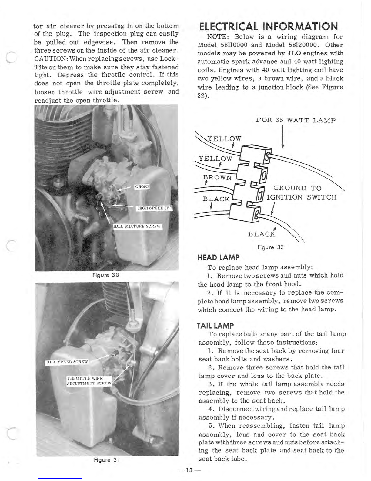
c
tor
air
cleaner
by
pressing
in
on
the
bottom
of
the
plug.
The
inspection
plug
can
easily
be
pulled
out
edgewise.
Then
remove
the
_
three
screws
on
the
inside
of
the
air
cleaner
.
CAUTION:
When
replacingscrews,
use
Lock
-
Tite
on
them
to
make
sure
they
stay
fastened
tight.
Depress
the
throttle
control.
If
this
does
not
open
the
throttle
plate
completely,
loosen
throttle
wire
adjustment
screw
and
readjust
the
open
throttle
.
Figure
30
Figure
31
ELECTRICAL
INFORMATION
NOTE
:
Below
is
a
wiring
diagram
for
Model
58110000
and
Model
58120000.
Other
models
may
be
powered
by
JLO
engines
with
automatic
spark
advance
and
40
watt
lighting
coils.
Engines
with
40
watt
lighting
coil
have
two
yellow
wires,
a
brown
wire,
and
a
black
wire
leading
to
a
junction
block
(See
Figure
32)
.
HEAD LAMP
FOR
35
WATT
LAMP
I
GROUND
TO
IGNITION
SWITCH
I
Figure
32
To
replace
head
lamp
assembly:
1.
Remove
two
screws
and
nuts
which
hold
the
head
lamp
to
the
front
hood.
2.
If
it
is
necessary
to
replace
the
com
-
plete
head
lamp
assembly,
remove
two
screws
which
connect
the
wiring
to
the
head
lamp.
TAIL LAMP
To
replace
bulb
or
any
part
of
the
tail
lamp
assembly,
follow
these
instructions:
1.
Remove
the
seat
back
by
removing
four
seat
back
bolts
and
washers.
2.
Remove
three
screws
that
hold
the
tail
lamp
cover
and
lens
to
the
back
plate.
3.
If
the
whole
tail
lamp
assembly
needs
replacing,
remove
two
screws
that
hold
th
e
assembly
to
the
seat
back.
4.
Disconnect
wiring
and
replace
tail
la
mp
assembly
if
necessa
r
y.
5.
When
reassembling,
fasten
tail
lamp
assembly,
lens
and
cover
to
the
seat
back
plate
with
three
screws
and
nuts
before
attach
-
ing
the
seat
back
plate
and
seat
back
to
the
seat
back
tube.
-13 -
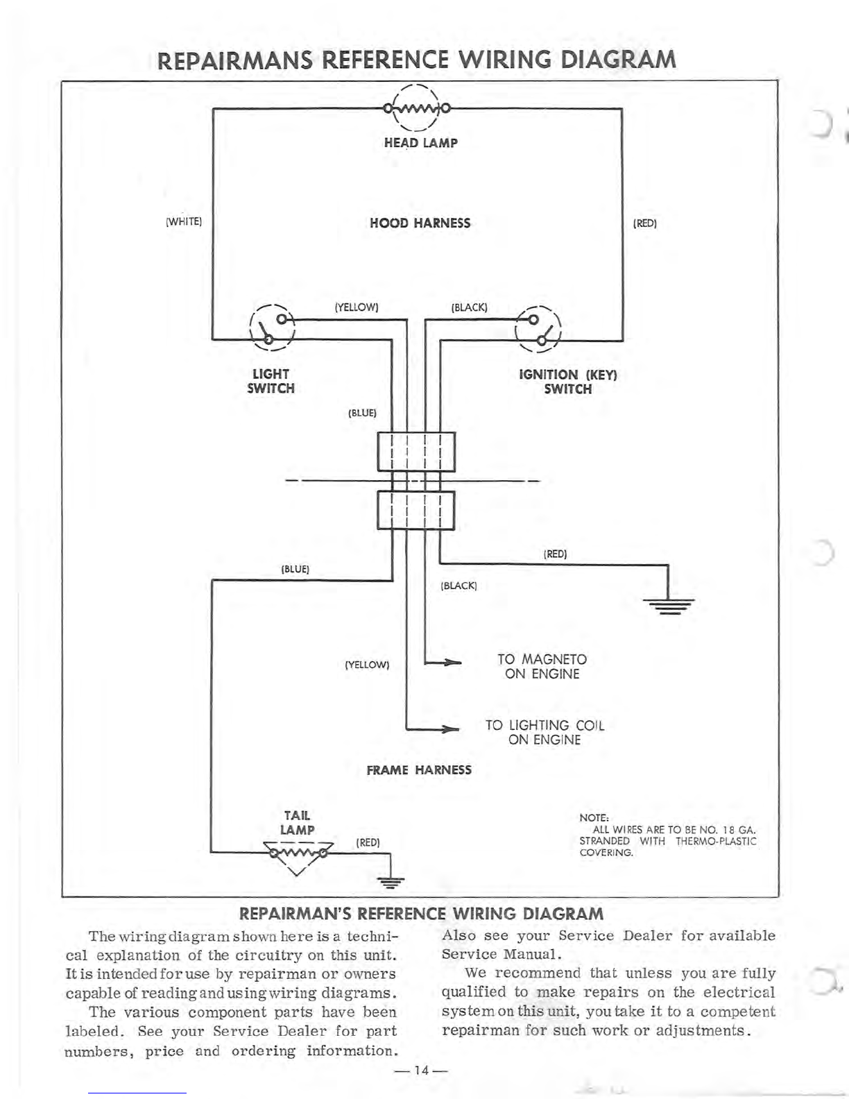
REPAIRMANS R
EFERE
NCE
WIRING
DIAGRAM
/'"
-....
( \
\ /
'--
HEAD LAMP
(WHIT
E)
HOOD
H
ARNESS
{
RED
}
LIGHT
SWI
TC
H
I
BLUE)
(
YE
LLOW)
(
BLUE
)
(YEL
L
OW)
{BLACK}
{BLACK}
IG
NI
TION (
KE
Y)
S
WIT
CH
{
RED
}
TO
M
AG
N
ETO
ON ENGINE
TO
LI
GHTING COIL
ON
ENGINE
FRAME HARN
ESS
TAIL
LAMP
NOT
E:
ALL WIRES
ARE
TO
BE
NO.
18
GA.
ST
RANDED
WITH
THERMO·PLASTIC
COVERING.
REPAIRMAN'S
REFERENC
E
WIRING
DIAGRAM
The
wiring
diagram
shown
here
is
a
techni
-
cal
explanation
of
the
circuitry
on
this
unit
.
It
is
intended
for
use
by
repairman
or
owners
capable
of
reading
and
using
wiring
diagrams
.
Als o
see
your
Service
Dealer
for
available
Ser
vice
Manual.
We
recommend
that
unless
you
are
fully
qualified
to
make
repairs
on
the
electrical
sy
s
tem
on
this
unit,
you
take
it
to a
competent
repairman
for
such
work
or
adjustments
.
The
variou
s
component
parts
have
been
labeled.
See
your
Service
Dealer
for
part
numbers
,
price
and
order
ing i
nformation.
-
14
-
J

)
)
c
LUBRICATION INSTRUCTIONS
PART
LOCATION
TYPE
OF
LUBRICATION
FREQUENCY
Steering
Spindles
Grease
zerk
on
spindles
Low
Temperature
grease
50
hours
(See
Figure
2)
Boggie
Wheels
Grease
zerk
in
center
of
Low
temperature
grease
50
hours
Boggie
Wheel
(See
Figure
22)
Steering
End
of
handle
column
Light
engine
oil
50
hours
Driving
Clutch
Remove
"U"
bolt
for
Light
engine
oil
Every
25
hours
lubrication
(See
FIgure
13)
Driven
Clutch
End
of
pully
shaft
Light
engine
oil
25
hours
(
See
Figure
18)
Chain
Housing
With
access
plug
removed
Light
engine
oil
50
hours
(See
Figure
16)
FUEL
MIXTURE
JLO
252-292
First
25
Hours
Mag
Type
2054-SRB
x
18
20
- 1
First
40
Hour
s
20
-1
After
25
Hours
25
-1
After
40
Hours
25 - 1
FUEL
MIXTURE INSTRUCTIONS
The
correct
oil-gasoline
ratio
is
24:1
or
1/3
pint
oil
to a
gallon
of
gasoline.
Too
much
oil
will
cause
carbon
deposits.
Too
little
oil
will
cause
insufficient
lubrication.
WARNING:
Gasoline
and
oil
should
be
mixed
at
temperatures
above
freezing.
Below
freez-
ing,
gas
and
oil
mix
with
difficulty.
Mix
with
care
or
damage
to
engine
could
result.
Use
only
a good
grade
of
SAE
30
non-
detergent
automotive
engine
or
outboard
motor
oil.
Do
not
use
light
duty
oils
for
multi-
visc
o
sity
oils.
Use
a good
grade
of
r e
gular
gasoline.
Use
fr
e
sh
gasoline
only.
Do
not
use
gasoline
left
over
from
summer
uses.
Mix
the
gasoline
and
oil
thoroughly
in
a
separate
clean
container
kept
for
this
purpose
only.
Bes
t
way
to
insure
good
mix
is
to
add
oil
to
an
empty
or
about
half
-
fuli
container
and
then
fill
with
gas
oline.
Mix
thorough
ly.
Fill
gasoline
tank
on
Ski
-
Daddler
from
this
separate
container
of
mixed
fuel.
Use
a
funnel
with
a
fine
screen
strainer
when
fill-
ing
tank.
OILS AND ADDITIVES
We do
not
recommend
the
use
of
additives
for
the
fuels
to
be
used
in
the
engines
of
the
Ski
-
Daddler
or
Snow
Clipper.
We
have
re-
ceived
comments
from
the
field
that
STP
and
Mercury
outboa
rd
oils
have
caused
problems.
Some
outboard
motor
oils
contain
a
deter-
gent
that
works
well
in
an
outboard,
however,
an
outboard
operates
ata
much
lower
temper
-
ature
because
it
is
water
co
o
led
and
for
this
reason
we do
not
recommend
outboard
oil.
Use
an
oil
for
air
cooled
2
cycle
engines
such
as
Ca
strol
or
a good no
n-detergent
#30
or
#40
motor
oil.
If
you
experience
a
problem
with
moisture
in
the
fuel
system
a
small
amount
of
Dri-Gas
or
equivalent
may
be
used.
-15 -

~
0-
I
For Parts
Li
st -
Se
e Page 17
ALL
UNN
UM
BE
R
ED
PARTS
INTER-CHANGEABLE
WIT
H OPPOSITE SIDE
7
44
40
46
'e
3 / \
43
()
~
~
'--..
-?,®
\
~e
@
~
\%
~~-
-~
\
42
OF'
39
38
l°
te
31
,---
I
19
*' G
\\
l~
_
II
r,II
...
1-
11'
-
19
17
17
_
1I11
v
-2
3
.ft
U
~
~
~
26
~,
18
23
..
AMF SKI-DADDLER
SNO
WM
OB
ILE
12
I
0--
I
74
_________
11
76-1
~
/\
l
~26
1)
______
~
8
o 0
.....
g
II>
26
~
BODY
PARTS
o
oJII..Q
o
=fi
73
d1
~
26
o
36
FIGURE
1
u
22
~
.,,",d
o 0
I)
,,0.::3
o 0
49
04
22
I
.","""
34
35
33
J
72
5~
'"
28
~
47
55
\..
I
68
,-
22
2\9
~
"
29
' "
26~
"1l-
70
::
Q
~
~--
9
<8'
64
75
B
El
El
IJ
U
I \
~
• • ' 2
5
~
8
~
J~
-
30
o
~
U
~
64
59
~
53
_-------
-y
~
0/
61
, __
________-
•
63
~
6
~6
0
II .
'
~l
y
~
65
.
~~
---
o .
. . •
62
,
......
6)'
....--,;,....
;
~~,
o
Ii~
~
~
"
16
25
-@
,/
"
"
3
~m
'\
,
~
24
27
67
T
'~~~
I
67
-~~~
..
~
~
58
32
69
c
c
Key
No
.
1
2
3
4
5
6
7
8
9
10
11
12
13
14
15
16
17
18
19
20
21
22
23
24
25
26
27
28
29
30
31
32
33
34
35
36
37
38
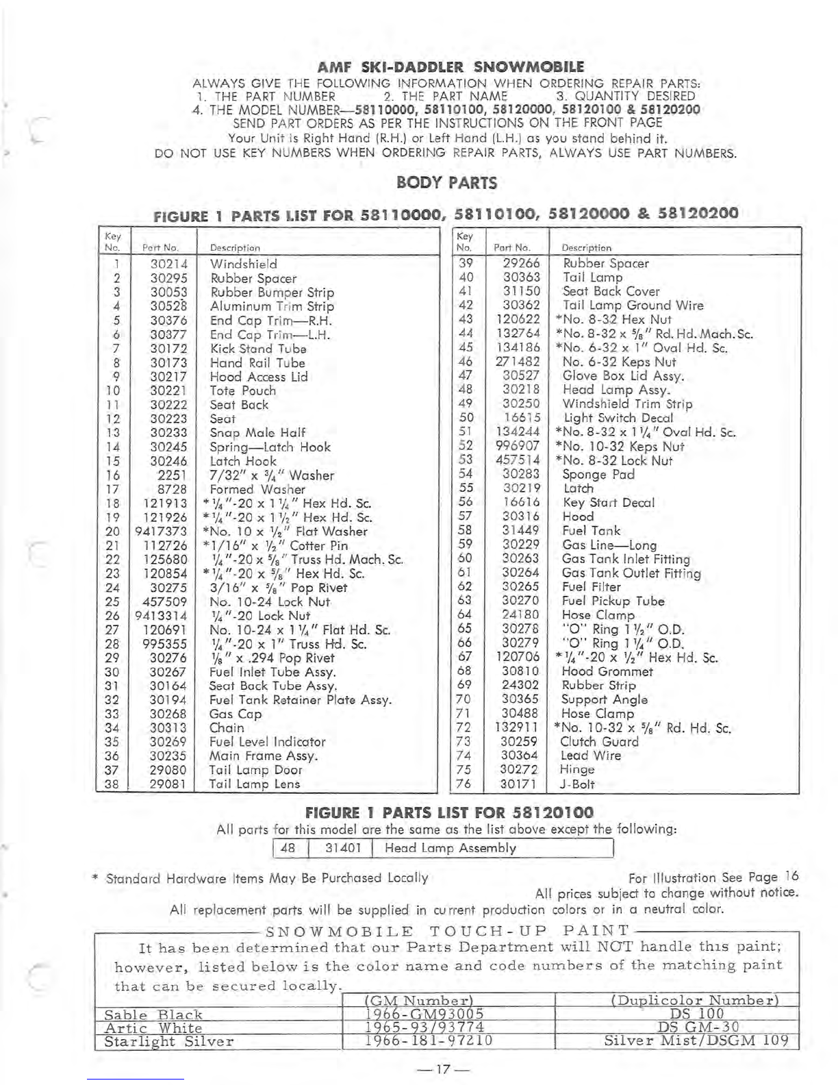
AMF
SKI-DADDLER
SNOWMOBILE
ALWAYS GIVE T
HE
FOLLOWING INFORMATION WHEN ORDERING
REPAIR
PARTS:
1.
THE
PART
N
UMBER
2.
THE
PART
NAME 3. QUANTITY
DESIRED
4.
TH
E MODEL N
UMBER
-
58110000,
58110100,58120000,
58120100
&
58120200
SEND
P
AR
T
ORDERS
AS
PER
THE
INSTRUCTIONS
ON
THE
FRONT
PAGE
Your Unit is Right
Hand
(R
.H
.)
or Left H
and
(L.H
.) as you stand
behind
it
.
DO NOT
USE
KEY
NU
MBERS
WHEN
ORDERI
NG R
EPAIR
PARTS,
ALWAYS
USE
PART
NUMBERS.
I
BODY
PARTS
FI
GURE
1 PARTS
LIST
FOR
58110000, 58110100,
58120000
&
58
1
20200
Key
Part
No
. De
script
i
on
No. Part
No.
Description
30214
Windshield
39 29266 Rubber Spacer
30295 Rubber Spacer 40 30363 Tail Lamp
30053 Rubber Bumper St
rip
30528
Aluminum
Tr
im Strip
30376 End Cap Trim
-R
.H
.
30377 End Cap
Tr
i
m-L.H.
30172 Kick Stand Tube
41 31150 Seat Back Cover
42 30362
Ta
il Lamp
Ground
Wire
43 120622
*No
. 8-32 Hex
Nut
44 132764
*No.
8-32 x %
II
Rd.
Hd.
Mach.
Sc.
45 134186
*No.
6-32 x 1"
Oval
Hd.
Sc
.
30173
Hand
Rail Tube 46 27 1482 No. 6-32 Keps
Nut
30217
Hood
Access Lid 47 30527
Glove
Box Lid Assy.
30221 Tote Pouch 48 30218 Head La
mp
Assy.
30222 Seat Back 49 30250
Winds
hield Trim Strip
30223 Seat 50 16615 Light Switch Decal
30233 Snap
Male
Half
51
134244
*No.
8-32 x 11/4"
Oval
Hd
.
Sc.
30245 Spring-Latch
Hook
52 996907
*No.
10-32 Keps
Nu
t
30246 Latch
Hook
53 457514
*No
. 8-32 Lock
Nut
2251 7
/32"
x %
II
Washer 54 30283 Sponge Pad
8728 Formed
Was
her 55 30219 Latch
12191 3 *
1/4
"-20
x 11//' Hex
Hd
.
Sc.
56 16616 Key Start Decal
121926 *
1/4
"-20
x 1
1/
2" Hex Hd.
Sc.
57 30316 Hood
9417373
*No
. 10 x
1f2
" Flat
Wa
sher 58 31449 Fuel Tank
112726 * 1
/16"
X
1/2"
Cotter
Pin
59 30229 Gas Line-Long
125680
1/4
"-2
0 x %
II
Truss
Hd
.
Mach
.
Sc
. 60 30263 Gas Tank
Inlet
Fitting
120854 * 1
/4
"-20
x %
II
Hex Hd.
Sc.
61
30264 Gas Tank
Outlet
Fitti
ng
30275
3/16"
x %
II
Pop Rivet 62 30265 Fuel Filter
457509
No
. 10-24 Lock
Nut
63 30270
Fuel
Pickup Tube
9413314
1/4
"-20
Lock
Nut
64 24180 Ho'
se
Clamp
120691
No.
10-24 x 1%
II
Flat Hd.
Sc.
65 30278
"0"
Ring 1%
II
O.D.
995355 1/4"-20 x
1"
Truss
Hd
.
Sc.
66 30279
"0"
Ring 1
1/4
II
O.D.
30276
1fa
II
x .294 Pop Rivet 67 120706 *
1/4
"-20
X
1/2"
Hex
Hd
.
Sc.
30267 Fuel Inlet Tube Assy. 68 30810
Hood
Grommet
30164 Seat Back Tube Assy. 69 24302 Rubber
St
rip
30194 Fuel Tank Retainer Plate Assy. 70 30365 Support A
ngle
30268 Gas
Cap
71
30488 Hose
Clamp
30313
Chain
72
132911 *No. 10-32 x %
II
Rd
. Hd.
Sc
.
30269 Fuel
Leve
l
Indicator
73 30259 Clutch
Guard
30235
Main
Frame Assy. 74 30364 L
ead
Wir
e
29080 Tail Lamp Door 75 30272
Hinge
29081 Tail Lamp
Lens
76 30171 J -Bolt
FIGURE 1 PARTS
LIST
FOR
58120100
All
parts for this
mode
l are the same as the list
above
except the
following:
I48 I 31401 I Head Lamp Assem
bly
I
* Standard
Hardware
Items
May
Be
Purchased L
ocally
F
or
Illustration
See
Page 16
All
prices subject
to
change
without
notice.
All
replacement parts
will
be
supplied
in
cu
rrent production colors
or
in a neutral
co
lor.
SNOWMOBILE
TOUCH
UP
PAINT
-
It
has
been
determined
that
our
Parts
Department
will
NOT
handle
thIS
paint;
however,
li
st
e d b e
low
is
the
color
name
and
code
numbers
of
the
matching
paint
that
can
b e
secured
locally.
(GM
Number)
(Dunlicolor
Number)
Sable
Black
1966
-
GMg3005
DS
100
Artic
White
1965-g3/g3774
DS
GM
-
30
Starlight
Silver
1966
-
181
-
97210
Silver
Mist/DSGM
109
-1
7 -
AMF
SKI-DADDLER
SNOWMOB
ILE
37
o 0
80
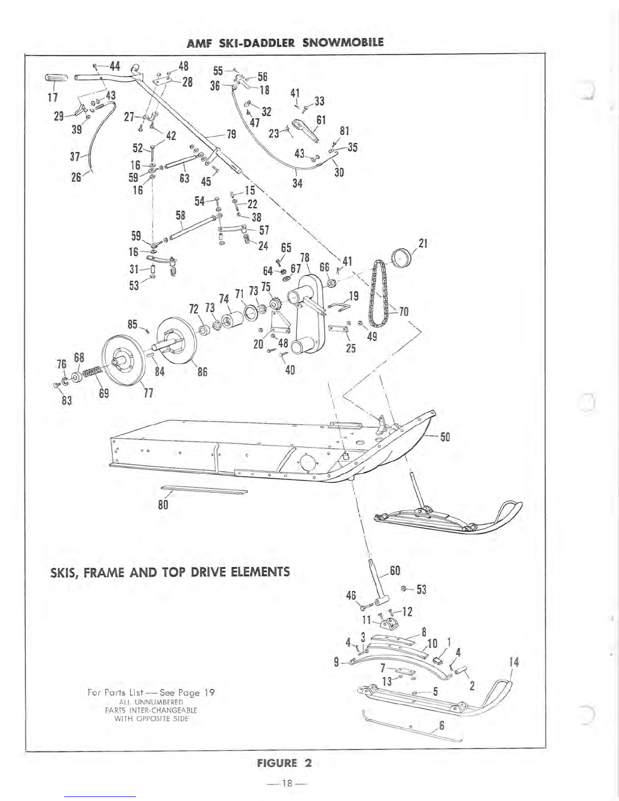
SKIS,
FRAME
AND
TOP
DRIVE
ELEMENTS
For Parts
List
-
See
P
age
19
A
LL
UNNUMBERED
PARTS
INTER·CHANGEABLE
WITH
OPPOSITE SIDE
FIGURE 2
-18 -
"
70
<3
~...
"-
o 9
49
)
25
/
•
•
c
c
AMF
SKI-DADDLER
SNOWMOBILE
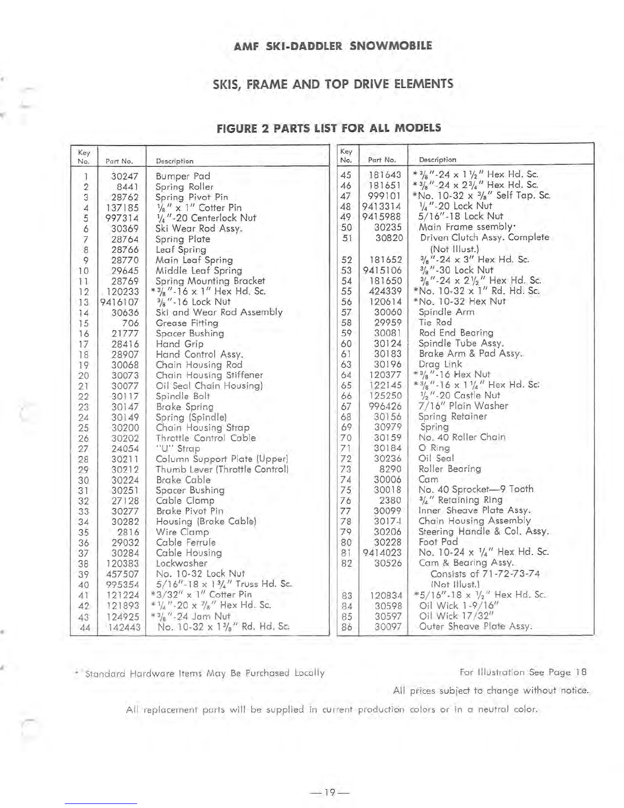
SKIS,
FRAME
AND
TOP DRIVE
ELEMENTS
FIGURE 2 PARTS LIST FOR
ALL
MODELS
Key
No
. Part No.
Description
Key
No
.
Part
No.
Description
1
30247
Bumper Pad
2 8441 Spring Roller
3
28762
Spring Pivot Pin
4
137185
1/8" X
1"
Cotter Pin
5
997314
1/4" -20 Centerlock
Nut
6
30369
Ski
Wear
Rod
Assy.
7
28764
Spring Plate
45
181643
*%"
-24 x
llj2"
Hex Hd.
Sc
.
46 181651
*%"-24
x
2%"
Hex Hd.
Sc
.
47 999101
*No
.
10-32
x
%"
Self Tap.
Sc.
48
9413314
1/4" -20 Lock
Nut
49
9415988
5/16"
-18 Lock
Nut
50
30235
Main
Frame
ssembly'
51
30820
Driven Clutch Assy. Complete
8
28766
Leaf Spring (Not !Ilust.)
9
28770
Main
Leaf Spring 52
181652
%"
-24 X
3"
Hex Hd.
Sc.
10
29645
Middle
Leaf Spring 53
9415106
%"
-30 Lock
Nut
11
28769
Spring
Mounting
Bracket
54
181650
%"
-24 x 21
/2" Hex Hd.
Sc.
12
120233
*3/
8
"-16
x
1"
Hex Hd.
Sc.
55
424339
*No.
10-32 x
1"
Rd.
Hd.
Sc
.
13
9416
107
%"
-16 Lock
Nut
56
120614
*No
. 10-32 Hex
Nut
14
30636
Ski
and
Wear
Rod
Assemb
ly
57
30060
Spindle
Arm
15
706
Grease Fitting 58
29959
Tie
Rod
16
21777
Spacer Bushing 59 30081
Rod
End
Bearing
17
28416
Hand
Grip
60
30124
Spindle
Tu
be Assy.
18
28907
Hand
Control Assy.
61
30183
Brake
Arm
& Pad Assy.
19
30068
Chain
Housing
Rod
63
30196
Drag Link
20
30073
Chain
Housing Stiffener 64
120377
*%"
-16 Hex Nut
21
30077
Oil
Seal Chain Housing) 65
122145
*
%"
-16 x 11
/4"
Hex Hd.
Sc:
22
30117
Spindle
Bolt
23
30147
Brake S
pring
66
125250
lj2"
-20 Castle
Nut
67
996426
7/
16"
Plain
Washer
24
30149
Spring (Spindle) 68
30156
Spring Retainer
25
30200
Chain Housing Strap
26
30202
Throttle Control Cable 69
30979
Spring
70
301
59
No
.
40
Roller Chain
27
24054
"U"
Strap
71
30184
o Ring
28 30211
Column
Support
Plate (Upper)
72
30236
Oil Seal
29
30212
T
humb
Lever (
Th
rottle Control)
73
8290
Roller Bearing
30
30224
Brake
Cable
74
30006
Cam
31
30251 Spacer Bushing 75
30018
No
.
40
Sprocke
t-
9 Tooth
32
271
28
Cable
Clamp
76
2380
3//'
Retaining Ring
33 30277 Brake Pivot
Pin
77
30099
Inner Sheave
Pl
at
e Assy.
34
30282
Housing (Brake Cable)
78
3017.+ Chain Housing
Assembly
35
2816
Wire
Clamp
79
30206
Steering Ha
ndle
& Col.
As-sy.
36
29032
Cable
Ferrule 80
30228
Foot Pad
37 30284
Cabl
e Housing
81
9414023
No
.
10-
24 X 1/4" Hex Hd.
Sc.
38 12
0383
Lockwasher 82 30
526
Cam & Bearing Assy.
39
457507
No.
10-32 Lock
Nut
Consists
of
71-
72
-
73-
74
40
995354
5/16"
-18 x 1
%"
Truss Hd.
Sc.
(Not I!lust
.)
41
121224
*3/
32"
x
1"
Cotter Pin 83
120834
*5
/
16"
-18 x
1//'
Hex Hd.
Sc.
42
121893
* 1/4"
-20
x
?fa"
Hex Hd.
Sc.
84
30598
Oil
Wick
1-9
/1
6"
43
124925
*%"-24
Jam
Nut
85 30597
Oil
Wick
17/
32"
44
142443
No
. 10-32 x 1
%"
Rd
. Hd.
Sc.
86
30097
Outer
Sheave Plate Assy.
*
Standard
Hardware
Items
May
Be
Purchased Locally For
Illustration
See
Page 18
All
prices subiect
to
change
without
notice.
Ali replacement parts
will
be
supplied
in current
production
colors
or
in a neutral color.
-19-

AMF
SKI-DADDLER
SNOWMOB
ILE
ENGINE,
ELECTRICAL
AND
FUEL
ELEMENTS
10
~
,
I I I
r...J
I I I I
~
~~
~
-
25
f D@ I
~
-
54
~
I I ,J
tf
: i
~
I
1-64
~-24
,
521
I I I
5
~
@
!
"-@!
@I
@
I I
Jepl;J;,
I
65
'
-
~~
.50,
I
,I
~
I I eo
'"
'5
I
...
1~.I~I9I
-
47
I , I _ 1
' I
~
I
! A ,!!
~
;
I !
f"1
51
i
a I
LJ
l)
Ll
___
1
2
-======6
e-
\
12
)9
FIGURE 3
-20
-
I
15
/
63
I
16
I
/
14
67
I
For Parts List -See
Page
21
ALL UNNUMBERED
PARTS
INTER-CHANGEABLE
WITH
OPPOSITE SIDE
67
18
[
17
/
-.~
I I J
62
61
66
•
)
This manual suits for next models
3
Table of contents
Other Ski-Daddler Offroad Vehicle manuals


Popular Offroad Vehicle manuals by other brands


Polaris
Polaris A12MH46AX Service manual

Polaris
Polaris Sportsman 9921309 owner's manual

Columbia ParCar
Columbia ParCar Gasoline and Electric Golf and Industrial Four Wheel... Service manual

Ducati Energia
Ducati Energia FREE DUCk Operating and maintenance manual

Yamaha
Yamaha KODIAK 700 YFM70KDXH owner's manual

Yamaha
Yamaha Apex RX10PA 2011 Supplementary service manual