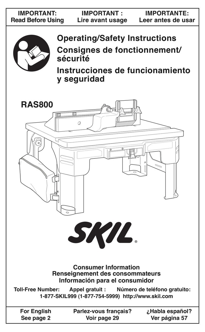
Skil SRT1039 User manual

WARNING: To reduce the risk of injury, the user must read and understand the
Owner’s Manual before using this product. Save these instructions for future reference.
AVERTISSEMENT : Afin de réduire les risques de blessure, l’utilisateur doit lire et
comprendre le guide d’utilisation avant d’utiliser cet article. Conservez le présent guide
afin de pouvoir le consulter ultérieurement.
ADVERTENCIA : Para reducir el riesgo de lesiones, el usuario debe leer y comprender
el Manual del operador antes de utilizar este producto. Guarde estas instrucciones para
consultarlas en caso sea necesario.
Owner’s Manual
Guide d’utilisation
Manual del propietario
For Customer Service
Pour le service à la clientèle
Servicio al cliente
Router Table
Table à Toupie
Mesa de Fresado
1-877-SKIL-999 OR www.skil.com
Model/ Modelo/ Modèle: SRT1039

2
TABLE OF CONTENTS
General Safety Warning for Bench Tools ............................3
Specific Safety Warnings for the Router Table......................4-5
Improper Fence Location and Workpiece Feed .......................6
Important Information about Extension Cords........................6
Grounding Instructions ...........................................7
Symbols ....................................................8-11
Parts List ..................................................12-13
Get To Know Your Router Table ...................................14
Specifications .................................................14
Router Table Setup ..........................................15-20
Router Table Operation.......................................21-22
General Routing Operations With The Router Table ...............23-26
Maintenance ..................................................27
Limited Warranty of SKIL Consumer Corded Power Tools .............28
WARNING
• Some dust created by power sanding, sawing, grinding, drilling and other construction
activities contains chemicals known to the State of California to cause cancer, birth defects or
other reproductive harm. Some examples of these chemicals are:
– Lead from lead-based paints.
– Crystalline silica from bricks, cement, and other masonry products.
– Arsenic and chromium from chemically-treated lumber.
• Your risk from these exposures varies, depending upon how often you do this type of work.
To reduce your exposure to these chemicals:
– Work in a well-ventilated area.
– Work with approved safety equipment, such as dust masks that are specially designed to
lter out microscopic particles.
– Avoid prolonged contact with dust from power sanding, sawing, grinding, drilling, and
other construction activities. Wear protective clothing and wash exposed areas with soap
and water. Allowing dust to get into your mouth or eyes or to lie on the skin may promote
absorption of harmful chemicals.

3
GENERAL SAFETY WARNINGS FOR BENCH TOOLS
Keep guards in place and in working order.
Remove adjusting keys and wrenches. Form a habit of checking to see that keys and
adjusting wrenches are removed from the tool before turning it on.
Keep the work area clean. Cluttered areas and benches invite accidents.
Don’t use in a dangerous environment. Don’t use power tools in damp or wet locations or
expose them to rain. Keep the work area well lit.
Keep children away. All visitors should be kept a safe distance from the work area.
Make workshop childproof with padlocks and master switches, or by removing starter
keys.
Don’t force tool. It will do the job better and safer at the rate for which it was designed.
Use the right tool. Don’t force tool or attachment to do a job for which it was not designed.
Wear proper apparel. Do not wear loose clothing, gloves, neckties, rings, bracelets, or other
jewelry which may get caught in moving parts. Nonslip footwear is recommended.
Wear protective hair covering to contain long hair.
Always use safety glasses. Also use a face or dust mask if the cutting operation is dusty.
Everyday eyeglasses only have impact resistant lenses. They are NOT safety glasses.
Secure work. Use clamps or a vise to hold work when practical. It’s safer than using your
hand and it frees both hands to operate the tool.
Don’t overreach. Keep proper footing and balance at all times.
Maintain tools with care. Keep tools sharp and clean for the best and safest performance.
Follow instructions for lubricating and changing accessories.
Disconnect tools before servicing or when changing accessories, such as blades, bits,
cutters, and the like.
Reduce the risk of unintentional starting. Make sure switch is in the off position before
plugging in.
Use recommended accessories. Consult the owner’s manual for recommended accessories.
The use of improper accessories may cause risk of injury to persons.
Never stand on the tool. Serious injury could occur if the tool is tipped or if the cutting tool is
unintentionally contacted.
Check damaged parts. Before further use of the tool, a guard or other part that is damaged
should be carefully checked to determine whether it will operate properly and perform its
intended function. Check for alignment of moving parts, binding of moving parts, brakeage of
parts, mountings, and any other condition that may affect tool’s operation. A guard or other part
that is damaged should be properly repaired or replaced.
Direction of feed. Feed work into a blade or cutter only against the direction of rotation of the
blade or cutter.
Never leave a tool running unattended. Turn power off. Don’t leave the tool until it comes to
a complete stop.

4
SPECIFIC SAFETY WARNINGS FOR THE ROUTER TABLE
For your own safety, read owner’s manual before using Router or Router Table.
Always wear eye protection.
Lift router table only by the table edges. Lifting table by any other surface could cause
personal injury.
Do not use the router table until all assembly and installation steps have been
completed. Prior to each use, verify that fasteners and the router clamps are tight. A
loose table or router is unstable and may shift in use, resulting in property damage or serious
personal injury.
Disconnect the router from the power supply before installing router into the table,
making adjustments, changing accessories, removing the router from the table,
performing maintenance, or storing the tool. Such precautionary safety measures reduce
the risk of unintentional tool operation.
Do not plug router motor power cord into standard wall outlet. Always plug router cord
into the router table switch box. Power tool switches and controls need to be within your
reach in emergency situations.
Do not permit fingers to touch terminals on the plug when inserting or removing plug
from the outlet. Risk of Electric Shock.
Before connecting router or vacuum to router table switch box, ensure that the router
or vacuum switch is off and that the router table switch box is unplugged. Such
precautionary safety measures reduce the risk of unintentional tool operation.
Before using the router table, verify that the router is securely clamped to the router
table base. While working, periodically check the router base fastener clamping
tightness. Vibrations from cutting operations can cause router motor clamps to loosen and the
router motor may fall from the table.
Before starting to work, ensure that the power cords from the router accessories, the
switch box, and the extension cord do not and cannot come in contact with the router
or any moving parts of the router. Such precautionary safety measures reduce the risk of
injury due to loss of control.
Do not use the router table without the overhead guard unless required by a particular
cutting operation. Replace the guard immediately after completion of cutting operation.
Remove all dust, chips, and any other foreign particles that can affect its function. The
guard will aid in keeping hands from unintended contact with the rotating bit.
Do not use bits that have a cutting diameter that exceeds the clearance hole in the
tabletop insert plate or insert rings. The bit could contact the insert plate or insert ring,
throwing fragments.
Never use dull or damaged bits. Damaged bits can snap during use. Dull bits require more
force to push the workpiece, possibly causing the bit to break or the material to kick back.
Handle sharp bits with care. Such precautionary safety measures reduce risk of injury.
Do not alter insert ring or insert plate bit hole. Match the cutting diameter of the bit to
the inner diameter of the insert ring or insert plate bit hole such that the difference is
no less than 1/16” (1.6mm) on a side. Insert rings are meant to reduce the gap between the
cutting diameter of the bit and the table so that workpieces maintain full support of the table
while routing.
Install bit in accordance with instructions in the router manual. Securely clamp the
router bit in the collet chuck before making any cuts. Securing the bit before cutting
reduces the risk of the bit becoming loose during operation.

5
Never place your fingers near a spinning bit or under the guard when the router is
plugged in. Such precautionary safety measures reduce the risk of injury.
Never hold the workpiece on the outfeed side of the bit. Pressing the workpiece against
the outfeed side of the fence may cause material binding and possible kickback, pulling your
hand into the bit.
Guide the workpiece with the fence to maintain control of the workpiece. Do not place
the workpiece between the router bit and fence while routing the edge. This placement
will cause the material to become wedged, making kickback possible.
Only use routers for working with wood, wood-like products, plastic, or laminates. Do
not use router and router table for cutting or shaping metals. Be sure workpiece does
not contain nails or other hard objects. Cutting nails may cause loss of control of the tool or
workpiece.
Never start the tool when the bit is engaged in the material. The bit-cutting edge may grab
the material, causing loss of control of the workpiece.
Feed the workpiece only against the rotation of the bit. Do not “back feed” the
workpiece into the bit. The bit rotates counterclockwise as viewed from the top of the table.
“Back feeding” will cause the workpiece to “climb” up on the bit, pulling the workpiece and
possibly your hands into the rotating bit.
Do not feed the workpiece into the bit where the majority of the workpiece is between
the fence and the bit. This creates a “fence trap” which is a hazardous situation due to the bit
being exposed. This will cause the work to “climb-cut” away from the tabletop and may lead to
loss of control during operation.
Do not cut material that is warped, wobbly, or otherwise unstable. The router table is
designed to cut flat, straight, and squared materials. If the material is slightly curved
but otherwise stable, cut the material with the concave side against the table or fence.
Cutting the material with the concave side up or away from the table may cause the warped or
wobbly material to roll and kick back, causing the user to lose control.
Use auxiliary infeed and outfeed supports for long or wide workpieces. Oversize
workpieces without adequate support can ip off the table or cause the table to tip.
Use push stick, vertically and horizontally mounted featherboards (spring sticks), and
other jigs to hold down the workpiece. Push sticks, featherboards, and jigs eliminate the
need to hold the workpiece near the spinning bit.
Never let go of the workpiece when routing until the cut has been completed and the
workpiece is completely clear of the bit. Such precautionary safety measures reduce the
risk of injury and property damage. Featherboards aid in holding the workpiece in position
when routing on a router table. They are not intended to hold the workpiece in place alone
when the workpiece is in contact with the bit, or at any other time when the bit is turning.
Always hold the workpiece against the router table fence when routing. Such
precautionary measures increase accuracy in routing and improve control of the workpiece,
reducing the risk of injury.
Never leave the router unattended while it is running or before it comes to a complete
stop. Such precautionary safety measures reduce the risk of injury and property damage.
Do not use the table as a workbench or work surface. Using it for purposes other than
routing may cause damage and make it unsafe to use in routing.
Never stand on the table or use as a ladder or scaffolding. The table could tip or the cutting
tool could be accidentally contacted.
When servicing the tool, use only recommended SKIL replacement parts. Use of
unauthorized parts or failure to follow maintenance instructions can result in personal injury.

6
IMPROPER FENCE LOCATION AND WORKPIECE FEED
WARNING Do not feed the workpiece
where the majority of the
workpiece is between the fence and the bit.
This creates a “fence trap” which is dangerous
for two reasons:
• The front of the bit is exposed during the
cutting operation (Fig. A).
• The bit can “Climb-cut,” where the bit enters
the workpiece in the same direction as the
feed direction. This is likely to cause the
workpiece to “climb” away from the tabletop
and may lead to loss of control during
operation (Fig. A).
WARNING Feed the workpiece only
against the rotation of the
bit. Do not “back feed” the work into the bit.
The bit rotates counterclockwise as viewed
from the top of the table. “Back feeding” the
work is dangerous for two reasons:
• It will cause climb-cutting where the
workpiece can “climb” off the tabletop in
the direction of the bit rotation, pulling the
workpiece and possibly your hands into the
rotating bit (Fig. B).
• It is difcult to keep the workpiece against
the fence face as the bit rotation will push the
workpiece away from the fence.
IMPORTANT INFORMATION ABOUT EXTENSION CORDS
WARNING An extension cord with adequate size conductors that is capable of
carrying the current for your tool must be used. This will prevent
excessive voltage drop, loss of power, or overheating. Grounded tools must use 3-wire
extension cords that have 3-prong plugs and receptacles.
NOTE: The smaller the gauge number, the heavier the cord.
RECOMMENDED SIZES OF EXTENSION CORDS FOR 120-VOLT ALTERNATING
CURRENT TOOLS
Tool's
Ampere
Rating
Cord Size in A.W.G Wire Size in mm2
Cord Length in Feet Cord Length in Meters
25 50 100 150 15 30 60 120
3-6 18161614 0.75 0.75 1.5 2.5
6-8 18 16 14 120.75 1.0 2.5 4.0
8-10 18 1614120.75 1.0 2.5 4.0
10-12 161614 12 1.0 2.5 4.0 -
12-16 1412- - ----
Fig. A
Direction of
feed
Workpiece
Exposed bit
Fig. B
Workpiece
Correct
direction of
feed
Incorrect
direction
Climb-cutting

7
GROUNDING INSTRUCTIONS
In the event of a malfunction or breakdown, grounding provides a path of least resistance for
electric current to reduce the risk of electric shock. This tool is equipped with an electrical cord
that has an equipment-grounding conductor and a grounding plug. The plug must be plugged
into a matching outlet that is properly installed and grounded in accordance with all local codes
and ordinances.
Do not modify the plug provided. If it will not t into the outlet, have the proper outlet installed
by a qualied electrician.
Improper connection of the equipment-grounding conductor can result in a risk of electric
shock. The conductor with insulation that has an outer surface that is green with or without
yellow stripes is the equipment-grounding conductor. If repair or replacement is necessary, do
not connect the equipment-grounding conductor to a live terminal.
Check with qualied electrician or service personnel if the grounding instructions are not
completely understood, or if in doubt as to whether the tool is properly grounded.
Use only 3-wire extension cords that have 3-prong grounding plugs and 3-pole receptacles
that accept the tool’s plug.
Repair or replace damaged or worn cord immediately.
This tool is intended for use on a circuit that has
an outlet (sketch B). The tool has a grounding
pin (sketch A). A temporary adapter (sketches
C and D) may be used to connect this plug to
a 2-pole receptacle (sketch C), if a properly
grounded outlet is not installed by a qualied
electrician. The green-colored rigid ear, lug, and
the like, extending from the adapter must be
connected to a permanent ground, such as a
properly grounded outlet.
A.
B. C.
D.
Grounding
pin
Grounded means
Cover of
grounded
outlet box
Metal
screw

8
SYMBOLS
Safety Symbols
The purpose of safety symbols is to attract your attention to possible dangers. The safety
symbols and the explanations with them deserve your careful attention and understanding. The
symbol warnings do not, by themselves, eliminate any danger. The instructions and warnings
they give are no substitutes for proper accident prevention measures.
WARNING Be sure to read and understand all safety instructions in this Owner's
Manual, including all safety alert symbols such as “DANGER”, “WARNING”,
and “CAUTION” before using this tool. Failure to following all instructions listed below may result
in electric shock, re, and/or serious personal injury.
The denitions below describe the level of severity for each signal word. Please read the
manual and pay attention to these symbols.
This is the safety alert symbol. It is used to alert you to potential
personal injury hazards. Obey all safety messages that follow this
symbol to avoid possible injury or death.
DANGER DANGER indicates a hazardous situation which, if not avoided, will
result in death or serious injury.
WARNING WARNING indicates a hazardous situation which, if not avoided,
could result in death or serious injury.
CAUTION CAUTION, used with the safety alert symbol, indicates a hazardous
situation which, if not avoided, will result in minor or moderate
injury.
Damage Prevention and Information Messages
These inform the user of important information and/or instructions that could lead to equipment
or other property damage if they are not followed. Each message is preceded by the word
“NOTICE”, as in the example below:
NOTICE: Equipment and/or property damage may result if these instructions are not followed.
WARNING The operation of any power tools can result in foreign
objects being thrown into your eyes, which can result
in severe eye damage. Before beginning power tool operation, always
wear safety goggles or safety glasses with side shields and a full face
shield when needed. We recommend a Wide Vision Safety Mask for use
over eyeglasses or standard safety glasses with side shields. Always use
eye protection which is marked to comply with ANSI Z87.1.

9
SYMBOLS (CONTINUED)
IMPORTANT: Some of the following symbols may be used on your tool. Please study them
and learn their meaning. Proper interpretation of these symbols will allow you to operate the
tool better and more safely.
Symbol Name Designation/Explanation
VVolts Voltage (potential)
AAmperes Current
Hz Hertz Frequency (cycles per second)
WWatt Power
kg Kilograms Weight
min Minutes Time
s Seconds Time
Wh Watt-hours Battery capacity
Ah Ampere-hours Battery capacity
øDiameter Size of drill bits, grinding wheels, etc.
n0No load speed Rotational speed, at no load
nRated speed Maximum attainable speed
…/min Revolutions or reciprocations per
minute (rpm)
Revolutions, strokes, surface speed,
orbits, etc. per minute
OOff position Zero speed, zero torque...
1,2,3,…
Ⅰ,Ⅱ,Ⅲ, Selector settings Speed, torque, or position settings.
Higher number means greater speed
Innitely variable selector with off Speed is increasing from 0 setting
Arrow Action in the direction of arrow
Alternating current (AC) Type or a characteristic of current
Direct current (DC) Type or a characteristic of current
Alternating or direct current
(AC / DC) Type or a characteristic of current
Class II tool Designates Double Insulated Construction
tools.
Protective earth Grounding terminal
Li-ion RBRC seal Designates Li-ion battery recycling
program
Read the instructions Alerts user to read manual

10
Symbol Name Designation/Explanation
Wear eye protection symbol Alerts user to wear eye protection
Always operate with two hands Alerts user to always operate with two
hands
Do not use the guard for cut-off
operations
Alerts user not to use the guard for
cut-off operations

11
SYMBOLS (CERTIFICATION INFORMATION)
IMPORTANT: Some of the following symbols for certication information may be used on your
tool. Please study them and learn their meaning. Proper interpretation of these symbols will
allow you to operate the tool better and more safely.
Symbol Designation/Explanation
This symbol designates that this tool is listed by Underwriters Laboratories.
This symbol designates that this component is recognized by
Underwriters Laboratories.
This symbol designates that this tool is listed by Underwriters
Laboratories, to United States and Canadian Standards.
This symbol designates that this tool is listed by the Canadian
Standards Association.
This symbol designates that this tool is listed by the Canadian
Standards Association, to United States and Canadian Standards.
This symbol designates that this tool is listed by the Intertek Testing
Services, to United States and Canadian Standards.

12
PARTS LIST
Refer to parts list below.
WARNING If ANY of the parts are missing, DO NOT attempt to assemble, install, or
use your router table until the missing parts have been found or replaced
and your router table has been properly and correctly assembled per this manual.
• For missing parts or technical assistance, call 1-877-SKIL-999.
• In order to simplify handling and to minimize any damage that may occur during shipping,
your router table comes mostly assembled. Repositioning of some parts will be required.
• Separate all parts from the packaging materials and check each part against the illustrations
and the parts list to make sure that all parts have been included. Do this before discarding
any of the packaging material.
Item Description Quantity
ARouter table assembly (including 6pcs pre-assembled bolts and 4pcs pre-
assembled screws) 1
BLeft and right table legs 1
CFence assembly 1
DFeatherboard assembly for fence 1
EFeatherboard assembly with a slide bar for tabletop surface 1
FMiter gauge assembly 1
GInsert ring set (3 rings per set)
G-1 Insert ring w/ Ø 11/16” (17.5mm) hole 1
G-2 Insert ring w/ Ø 1-1/4” (32mm) hole 1
G-3 Insert ring w/ Ø 1-3/4” (44.5mm) hole 1
HStarter pin 1
I5mm combination wrench (hex/ Phillips) 1
A
Router Table Assembly
4pcs Screws
6pcs Bolts
C
B
D

13
E
G
G1
G2
G3
H I
F
Tools Needed (Not Supplied)
4mm Hex Wrench

14
GETTING TO KNOW YOUR ROUTER TABLE
Fig. 1
Out-feed Clamping
Knob
Sideways
Clamping Knobs
Fence Assembly
Clamping Knob
Fence Assembly
Clamping Knob
Overhead guard
Out-feed fence
Insert ring
Featherboard
Toolbox
Fastening hole
Table leg
Integrated
safety switch
Router release
mechanism
Quick-clamp router
mounting Plate
Starter pin
Tabletop
Miter gauge
Featherboard
In-feed fence
Vacuum port
SPECIFICATIONS
Model No. SRT1039
Rating 120V~,60Hz,15A
Table size 26"x16"x14" (66x40.6x35.6 cm)
Miter slot 3/4" (19 mm)
Fence length 24" (60.96 cm)
Maximum Cutter Diameter 1-5/8’’ (41.3 mm)

15
ROUTER TABLE SETUP
WARNING Always unplug the router table before attaching accessories or
making any adjustment.
Attaching the Legs to the Table (Fig. 2)
NOTE: The router table assembly has six hex socket bolts pre-installed on the table base for
attaching the two table legs.
1. Place the router table assembly upside down on a at, level surface.
2. Loosen the three bolts on the right side of the table base.
3. Open the toolbox door and lower one of the legs onto the table base as shown. Make sure
that two bolts are inserted through the two holes in the toolbox.
4. Push the leg towards the center of the table, until the third bolt is inserted into the slot at the
center of the inner side of the leg. At the same time make sure that the tongue of the switch
mounting plate ts into the slot of the leg.
5. Tighten the three securing bolts with the included 5mm combination wrench.
6. Repeat the above process with the other table leg.
NOTE: The opening direction of both toolboxes should be on the side of the integrated safety
switch.
a
b
Fig. 2
Table base
Switch mounting plate Tongue
Toolbox
Slot
Removing the Quick-Clamp
Router Mounting Plate from the
Table Base (Fig. 3a and 3b)
This router table includes a quick-clamp router
mounting system, which has been pre-installed
at the factory prior to shipment.
1. Using the included 5mm combination wrench,
loosen and remove the four Phillips screw
assemblies which are securing the mounting
plate to the table (Fig. 3a). Save the bolts for
future use.
Fig. 3a

16
2. Place the router table assembly upside down
on a at, level surface (Fig. 3b).
3. Push the clamp-handle to the left to open the
router release mechanism (a).
4. Lift up the Tab 1 on the mounting plate to
remove it from the table base (b).
Attaching the Quick-Clamp
Mounting Plate to the SKIL
Routers RT1322-00
(Fixed Base Only) and RT1323-00
WARNING Disconnect the router
from the power supply
before installing router into the table,
making adjustments, changing accessories,
removing the router from the table,
performing maintenance, or storing the tool.
Such precautionary safety measures reduce
the risk of unintentional tool operation.
1. Place the router upside down so that it is
resting on its top cap (Fig. 4a)
2. Remove the plastic subbase from your router
by removing the three screws using the
included 5mm combination wrench. Keep the
three screws to be used in the future step 4.
NOTE: If you wish to mount the router with the
subbase, you may need to purchase longer
fasteners. Using the subbase reduces the
range of the cutting depth.
3. If you want to use a vacuum during your
work, this is a convenient time to install the
vacuum adaptor on the router. See your
router manual for the information about the
vacuum adaptor assembly.
4. Align the three mounting plate holes with the
router base holes, also make sure to align the
depth-adjustment rod on the router with the depth-adjustment hole on the mounting plate.
5. Securely mount the quick-clamp mounting plate to your router using the three screws from
Step 2 (Fig. 4b).
6. Always make sure the screws are fully seated on the mounting plate and the router base is
rmly against the mounting plate to ensure secure mounting.
NOTE: The Mounting plate must be mounted with the Tab 2 facing up.
a
b
Fig. 3b
Clamp-
handle
Tab 1
Fig. 4a Subbase
Fig. 4b
Tab 2
Quick-clamp
Mounting Plate
Depth-Adjustment
Hole

17
Installing the Quick-Clamp
Mounting Plate and Router to the
Router Table
WARNING Before using the router
table, verify that the
router is securely clamped in the router
table base. While working, periodically
check the router base fasteners clamping
tightness. Router motor vibration can loosen
fasteners during use, causing the router to fall
from the table.
1. Place the router table assembly upside down
on a at, level surface.
2. Align the notches on the mounting plate with
the protruding parts on the table base, then
insert the edge of the mounting plate (with
two notches) under the pressing plate on the
table base (Fig. 5a).
3. Put down the mounting plate slowly until
its right edge is against the clamp-handle
of the router release mechanism and seats
at on the table base. The clamp-handle
will snap in place to lock the mounting plate
automatically.
4. Flip the router table upright, with the legs
standing on a at, level surface.
5. Align the four holes on the tabletop with the
holes on the mounting plate.
6. Insert the four Phillips screw assemblies
through the four holes in the router tabletop
surface and the holes in the mounting plate. Securely tighten the screws with the 5mm
combination wrench (Fig. 5b).
Installing the Insert Ring (Fig.6)
This router table includes three tabletop insert
rings with the following different opening
diameters: (G-1) 11/16” (17.5mm) opening
diameter, (G-2) 1-1/4” (32mm) opening diameter
and (G-3) 1-7/8” (44.5mm) opening diameter.
WARNING Insert rings are meant to
reduce the gap between the
cutting diameter of the bit and table so that
workpieces maintain full support of the table
while routing. The proper size insert ring
depends on the size and shape of the cutter.
When inserted, the insert ring opening should
be within 1/4” (6.3mm) of the outermost edge
of the cutter.
WARNING Do not alter insert ring or insert plate bit hole. Match the cutting diameter of
the bit to the inner diameter of the insert ring or insert plate bit hole such
that the difference is no less than 1/16” (1.6mm) on a side.
Fig. 5b
a
b
Fig. 5a
Pressing
plate
Protruding
Part Notch Clamp-handle
Fig. 6
Tab

18
WARNING Do not use the router table with bits over 1-3/4” (44.5mm) in diameter. Bits
larger than 1-3/4” can contact insert plate or insert ring, throwing fragments.
The insert ring should t into the tabletop hole completely. Use a ne le or emery board to
remove excess plastic or rough edges that may cause the insert ring to protrude above the
table surface.
1. Select the insert ring that best accommodates the router bit to be used.
2. Position the insert ring over the insert opening in the router table.
3. Press down evenly over the tabs until the insert ring locks into place.
4. To remove, pull up gently until the tabs disengage. When not in use, store insert rings in one
of the toolboxes or another convenient place.
WARNING Do not use, attempt to change, or remove tabletop insert rings from
the table unless the router is off and unplugged. Such precautionary
safety measures reduce the risk of unintentional tool operation.
Attaching the Fence Assembly to
the Tabletop (Fig. 7)
The fence comes pre-assembled. Loosen
the two fence assembly clamping knobs but
don’t remove them from the two bolts before
attaching the fence assembly to the tabletop.
1. Attach the fence to the tabletop by inserting
the two round-head, square-neck bolts on
the fence into the holes of the keyhole slots
on the tabletop, making sure the bolt heads
are below the inner surface of the tabletop
and can slide freely within the keyhole slot.
2. Tighten the fence assembly clamping knobs
to secure the fence assembly in the desired
position.
NOTE: Use the scale on the tabletop as a guide when aligning the fence for routing operations.
Once the fence is positioned and aligned correctly, tighten the fence assembly clamping knobs
SECURELY.
Attaching the Miter Gauge (Fig. 8)
1. Attach the miter gauge to the table by sliding
the miter-gauge bar into the slot on the table.
2. To adjust the miter angle, loosen the miter
gauge knob, rotate the miter gauge to the
desired angle and tighten the knob again.
Fig. 7 Fence Assembly
Clamping Knobs
Bolt
Keyhole Slot
Fig. 8
Bar
Miter-gauge
Knob

19
Attaching the Featherboards
NOTE: The front and back side of each featherboard is marked to indicate the proper feed
direction.
The featherboards come pre-assembled. Loosen but do not remove the large clamping knobs
from each bolt.
Attach the featherboard (without the slide bar) to the fence
1. Attach the featherboard to the fence by inserting the two round-head, square-neck bolts into
the slot in the fence, making sure the bolt head are snapped into the slot and can slide freely
(Fig. 9a).
2. Tighten the large clamping knobs to secure the featherboard to the fence (Fig. 9b).
Fig. 9a Fig. 9b
Feed Direction Mark
Attach the featherboard (with a slide bar) to
the tabletop surface (Fig. 9c)
1. Attach the featherboard to the tabletop
surface by inserting the slide bar, attached
the feather board, into the slot on the table,
making sure the slide bar can slide freely
within the slot.
2. Tighten the large clamping knobs to secure
the feather board to the tabletop.
Fig. 9c
Slide bar

20
Permanent Attachment to a
Workbench (Fig. 10)
1. Place the router table on a sturdy surface,
such as workbench.
2. While holding the router table in place, mark
the four locations of the fastening holes in
each of the legs onto the work surface.
3. Remove the router table.
4. Drill a Ø3/8”-15/32” (9.5mm-12mm) hole into the
workbench at each of the four marked locations.
5. Place the router table on the workbench and
align the holes in the table legs with the holes
in the workbench.
6. Secure the router table to the workbench with four bolts 5/16” (M8) x L and nuts (not included).
– L=2-1/2” (63mm) for 1” thickness of workbench
– L=3” (76mm) for 1-1/2” thickness of workbench
7. Tighten the bolts securely.
To Adjust the Cutting Depth (Fig. 11)
The router table features a depth-adjustment
hole to permit over-table depth adjustment
(OTA) for SKIL routers RT1322-00 (xed base
only) and RT1323-00.
1. Loosen the motor clamp on the router.
See your router manuals for the detailed
instructions.
2. Insert a 4mm hex wrench (not included)
through the depth-adjustment hole and into
the depth-adjustment rod of the router, then
turn the hex wrench to move the router collet
down or up.
3. When the desired cutting depth is set, tighten
the motor clamp.
NOTE: See your router manuals for the detailed instructions about the motor clamp operation.
Fig. 10
Fastening Hole
Fig. 11
OTA
Table of contents
Languages:
Other Skil Indoor Furnishing manuals
Popular Indoor Furnishing manuals by other brands

Ercol
Ercol Capena 3573 instruction manual

Mooreco
Mooreco Compass MakerSpace 9169 Series Assembly instructions

leco
leco 39212 103 manual

Weelko
Weelko Practi 1021A quick start guide

Politorno
Politorno ESTANTE COM VISTAS Assembly instructions

Noble House Home Furnishings
Noble House Home Furnishings ROCKING CHAIR Assembly instructions