Skoda ABA 700 002 User manual

ŠkodaOriginální příslušenství
ŠkodaOriginal Zubehör
ŠkodaGenuine Accessories
SIMPLY CLEVER
Objednací číslo/ Bestellnummer/ Order Number
Montážní návod
Montageanleitung
Fitting instructions
Instrucciones de montaje
Instructions de montage
Istruzioni di montaggio
Monteringsanvisning
Montageaanwijzing
Instrukcja montażowa
Montážny návod
Руководство по монтажу
Szerelési útmutató
Instrucţiuni de montaj
ŠkodaFabia (5J)
ŠkodaFabia
Combi (5J)
Škoda
Roomster (5J7)
Zadní reproduktory
Hintere Lautsprecher
Rear speakers
ABA 700 002

1
2

3
4

5

6

7
8

9

CZ
ZADNÍ REPRODUKTORY
Produkty příslušenství jsou určeny k odborné montáži. Škoda Auto doporučuje prová-
dět montáž u smluvních partnerů.
Sadu zadních reproduktorůlze montovat na vozy s levostranným i pravostranným
řízením.
- 1 -
Seznam dílůsady zadních reproduktorů
Název dílu KusůPozice
Hlubokotónový reproduktor 2 A
Výškový reproduktor 2 B
Svazek elektrické instalace „autorádio • B-sloupek“ 1 C
Svazek elektrické instalace
„B-sloupek • hlubokotónový reproduktor“ 2 D
Svazek elektrické instalace
„hlubokotónový reproduktor • výškový reproduktor 2 E
Svorkovnice 4-pólová (dutinková) 2 F
Svorkovnice 2-pólová (nožová) 2 G
Nýt trhací 8 H
Spojovací dutinka (zatavovací) 4 J
Páska stahovací 10 K
Příchytka 10 L
Páska stahovací s příchytkou 1 M
Montážní návod 1
Postup montáže
Demontáž a zpětnou montáž jednotlivých dílůproveďte dle dílenských příruček.
- Po dobu montáže mějte odpojený akumulátor (je-li ve voze kódované autorádio, zjistěte
nejprve jeho kód).
- Vyjměte a odpojte autorádio.
- Demontujte:
- střední díl přístrojové desky,
- panel střední konzoly (popřípaděloketní opěrku - je-li ve výbavěvozu),
- spodní panel B-sloupku (oběstrany vozu),
- lištu prahu zadních dveří (oběstrany vozu),
- výplňzadních dveří a záslepku otvoru pro umístění reproduktoru (oběstrany vozu),
- Upozornění - u vozůFabia (5J) a Fabia Combi (5J) demontujte navíc nosičagregátu
zadních dveří s ohledem na těsnění nosiče agregátu (oběstrany vozu).,
- uvolněte pružnou průchodku v B-sloupku (oběstrany vozu) a zadní vkládané koberce včet-
něpříchytek (jsou-li ve výbavěvozu).
Jednotlivé úkony při montáži zadních reproduktorůproveďte na obou stranách vozu
stejným způsobem.

CZ - 2 -
- Schéma umístění svazkůelektrické instalace ve voze.
- 3 -
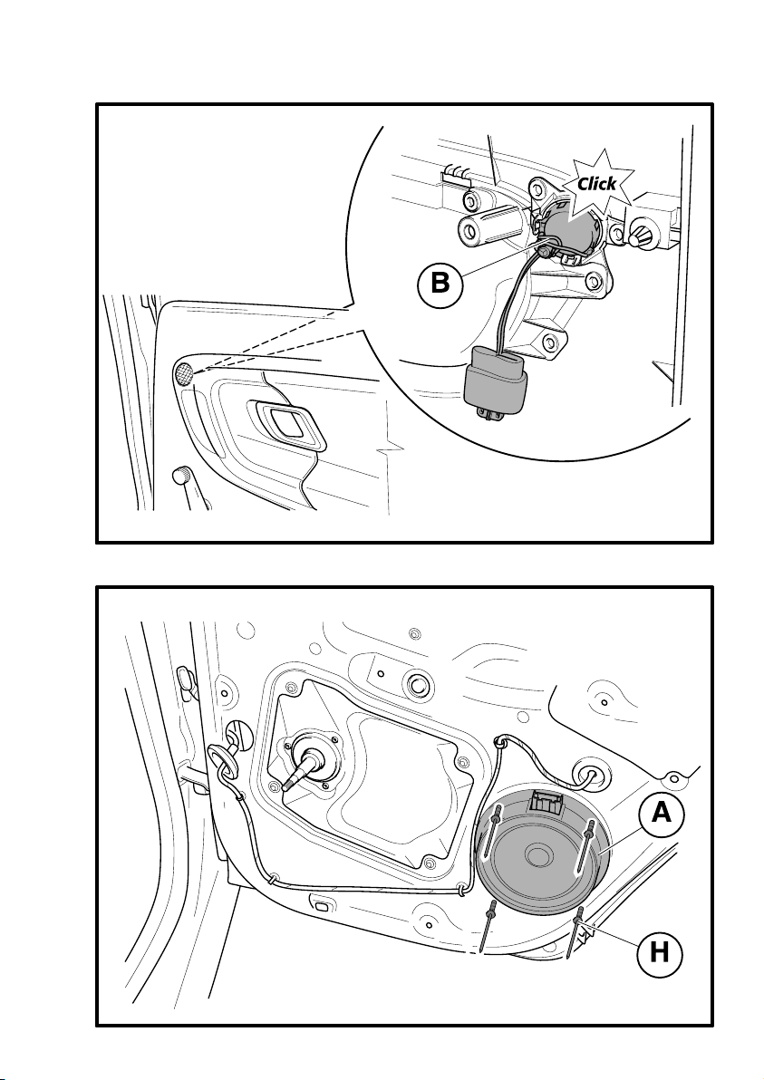
- Výškový reproduktor (B) nacvakněte do otvoru ve výplni dveří.
- 4 -
- Hlubokotónový reproduktor (A) ustavte do správné polohy a upevněte pomocí nýtů(H) do
otvoru v zadních dveřích.
Zapojení svazkůelektrické instalace zadních reproduktorů
Všechny svazky elektrické instalace zadních reproduktorůprotáhněte dle obrázku 2.
- 5 -
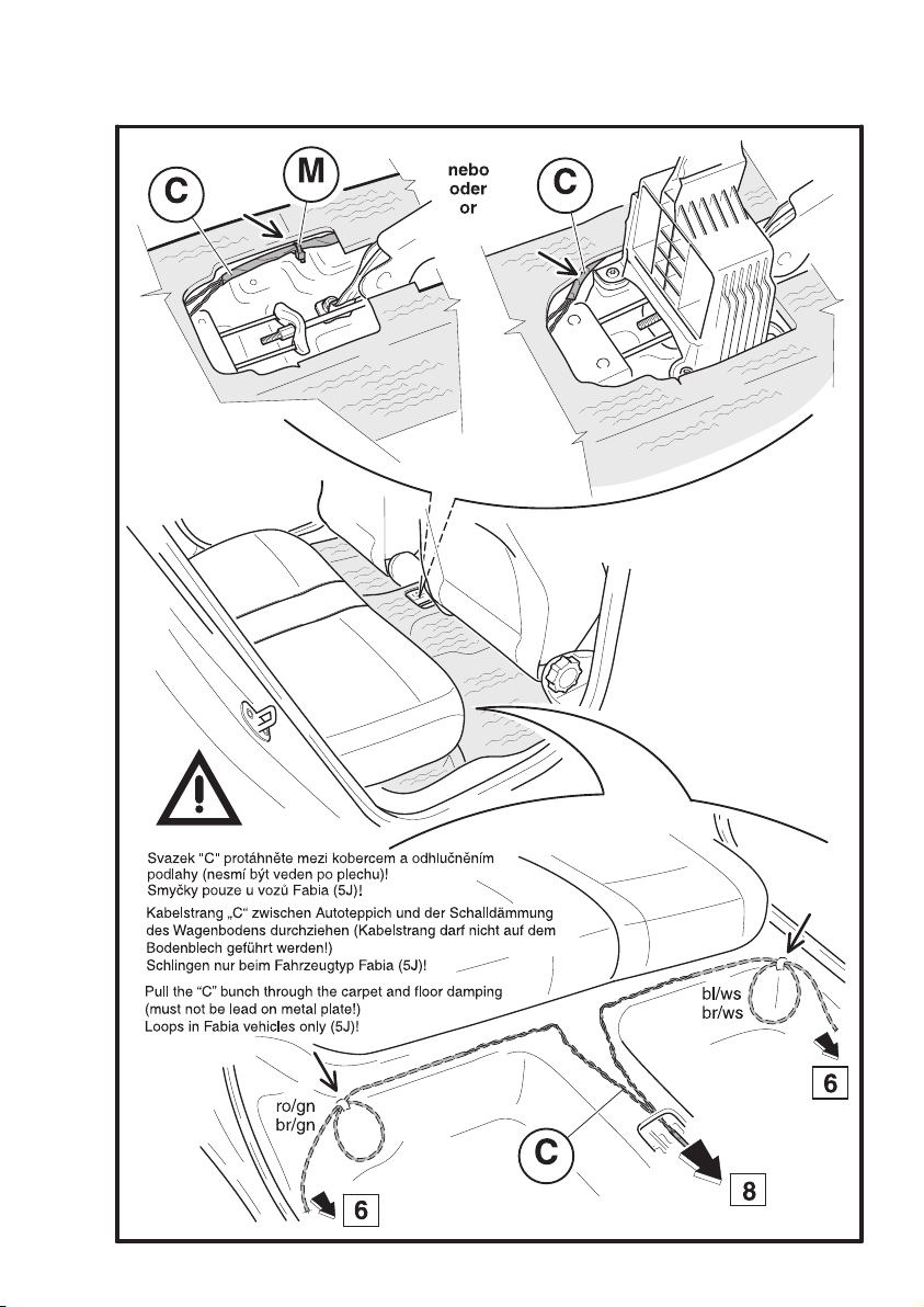
- Svazek elektrické instalace (C) veďte od zadních sedadel pod kobercem a dále po středovém
tunelu po jeho levé straně(kolem konzoly loketní opěrky, ruční brzdy a konzoly řadicí páky)
směrem dopředu až k plechové konzole přístrojové desky. Dále pak podél svazku stávající
elektrické instalace vozu až do otvoru pro autorádio (viz obr. 8). Upozornění. U pravostran-
ného řízení veďte svazek stejným způsobem, ale po pravé stravé stranětunelu.
- Není-li loketní opěrka ve výbavěvozu použijte k uchycení svazku elektrické instalace staho-
vací pásku s příchytkou (M).
- Rozdvojení vodičů ve svazku elektrické instalace (pro levou a pravou stranu vozu)
soustřeďte přibližnědo místa výkroje v koberci vozu.
- Levá strana vozu (ve směru jízdy) - modro/bílý vodič, hnědo/bílý vodič.
- Pravá strana vozu (ve směru jízdy) - červeno/zelený vodič, hnědo/zelený vodič.
- 6, 7 -
- Část svazku elektrické instalace (C) modro/bílý a hnědo/bílý vodičveďte dle obr. 5 pod
kobercem na levou stranu vozu k B-sloupku. Dále podél stávající elektrické instalace vozu
do otvoru pro pružnou průchodku dveří. (Druhou část svazku elektrické instalace (C) červe-
no/zelený vodič, hnědo/zelený vodičveďte stejným způsobem na pravou stranu vozu).
- Svazek elektrické instalace (D) protáhněte průchodkou dveří.
Upozornění. U vozůFabia (5J) a Fabia Combi (5J) dbejte na správné umístění svazku elektric-
ké instalace (D) v prostoru dveří(obr. 7).
- 9 -
- Vodiče svazkůzapojte následujícím způsobem.
Autorádio
- Originální autorádio (svorkovnice T8d)
- modro/bílý vodič(svazku C) - PIN 4
- hnědo/bílý vodič(svazku C) - PIN 8
- červeno/zelený vodič(svazku C) - PIN 1
- hnědo/zelený vodič(svazku C) - PIN 5

CZ
- Neoriginální autorádio (svorkovnice ISO 8-pólová)
- modro/bílý vodič(svazku C) - PIN 7
- hnědo/bílý vodič(svazku C) - PIN 8
- červeno/zelený vodič(svazku C) - PIN 1
- hnědo/zelený vodič(svazku C) - PIN 2
Osazenou svorkovnici T8d (popř. svorkovnici ISO) zasuňte do svorkovnice autorádia.
Připojte autorádio.
Vodiče v B-sloupku
- Levá strana vozu - je-li ve výbavěvozu svorkovnice T11a
- modro/bílý vodič(svazku C) - PIN 9
- hnědo/bílý vodič(svazku C) - PIN 8
- modro/bílý vodič(svazku D) - PIN 9
- hnědo/bílý vodič(svazku D) - PIN 8
- Pravá strana vozu - je-li ve výbavěvozu svorkovnice T11b
- červeno/zelený vodič(svazku C) - PIN 9
- hnědo/zelený vodič(svazku C) - PIN 8
- červeno/zelený vodič(svazku D) - PIN 9
- hnědo/zelený vodič(svazku D) - PIN 8
Osazené svorkovnice T11 zasuňte do sebe.
Upozornění. Nejsou-li svorkovnice T11 ve výbavěvozu, propojte vzájemněvodiče
svazku (C) a svazku (D) a zajistěte je pomocí spojovacích dutinek (J) dle obr. 6 (dbejte
na správnost barev vodičů při jejich propojování). Spojovací dutinky zatavte horko-
vzdušnou pistolí.
Hlubokotónový reproduktor (svorkovnice (F) 4-pól. dutinková)
- Levá strana vozu
- modro/bílý vodič(svazku D) - PIN 3
- hnědo/bílý vodič(svazku D) - PIN 1
- modro/bílý vodič(svazku E) - PIN 4
- hnědo/bílý vodič(svazku E) - PIN 2
- Pravá strana vozu
- červeno/zelený vodič(svazku D) - PIN 3
- hnědo/zelený vodič(svazku D) - PIN 1
- červeno/zelený vodič(svazku E) - PIN 4
- hnědo/zelený vodič(svazku E) - PIN 2
Výškový reproduktor (svorkovnice (G) 2-pólová nožová)
- Levá strana vozu
- modro/bílý vodič(svazku E) - PIN 1
- hnědo/bílý vodič(svazku E) - PIN 2
- Pravá strana vozu
- červeno/zelený vodič(svazku E) - PIN 1
- hnědo/zelený vodič(svazku E) - PIN 2

CZ - Osazené svorkovnice (F) a (G) zapojte do příslušných svorkovnic reproduktorů.
Svazek elektrické instalace (D) upevněte ve dveřích pomocí příchytek (L).
U vozůŠkoda Fabia (5J) upravte přebytečnou délku svazku elektrické instalace (C) do
smyčky dle obr. 5. Smyčku vložte pod koberec a popřípaději upevněte vhodnou lepicí
páskou. Dbejte na to, aby vodiče svazku nemohly být poškozeny příchytkami koberců.
Na vhodných místech upevněte svazky elektrické instalace zadních reproduktorůpo-
mocí stahovacích pásek (K) tak, aby nemohlo dojít k jejich poškození a během jízdy ne-
docházelo k vibracím nebo rušivým zvukům v interiéru vozu, maximálněvšak po 20ti
centimetrech.
Namontujte zpět všechny demontované díly (v případěnutnosti vyměňte poškozené příchyt-
ky). Připojte akumulátor a proveďte všechny úkony související s odpojením a znovu připoje-
ním akumulátoru.
Pomocí diagnostického přístroje nakódujte originální autorádio pro provoz s předními i zad-
ními reproduktory.
Zkontrolujte správné ustavení pružných průchodek do sloupkůa do dveří, aby nedo-
cházelo k zatékání do vozu.
Vyzkoušejte funkci reproduktorů.

DE
HINTERE LAUTSPRECHER
Die Zubehörteile sind zur fachgerechten Montage bestimmt. Škoda Auto empfiehlt, die
Montage von Vertragspartnern durchführen zu lassen.
Das hintere Lautsprecher-Set kann in Wagen mit Links- und Rechtslenkung montiert
werden.
- 1 -
Teileverzeichnis des hinteren Lautsprechersets
Teilebezeichnung Stückzahl Position
Tieftonlautsprecher 2 A
Höhenlautsprecher 2 B
Kabelsatz zur Installation von „Autoradio • B-Säule“ 1 C
Kabelsatz zur Installation von
„B-Säule • Tieftonlautsprecher“ 2 D
Kabelsatz zur Installation von
„Tieftonlautsprecher • Höhenlautsprecher 2 E
Klemmleiste (4-polige Buchsenklemme) 2 F
Klemmleiste (2-polige Messerklemme) 2 G
Reißniete 8 H
Verbindungshülse (schmelzbar) 4 J
Kabelbinder 10 K
Befestigungsclip 10 L
Kabelbinder mit Clip 1 M
Montageanleitung 1
Montagevorgang
Den Aus- und Wiedereinbau der einzelnen Teile laut der entsprechenden Werkstatthand-
bücher vornehmen.
- Für die Dauer der Montage muss der Akkumulator abgeschlossen sein (wenn im Wagen
ein codiertes Autoradio eingebaut ist - zuerst dessen Code feststellen).
- Autoradio herausnehmen und abschließen.
- Zu demontierende Teile:
- der mittlere Teil des Armaturenbrettes,
- Verkleidung der Mittelkonsole (ggf. die Armstütze - sofern in der Ausstattung enthalten),
- untere Verkleidung der B-Säule (an beiden Wagenseiten)
- Leiste an der Hintertürschwelle (an beiden Wagenseiten),
- die Füllung der Hintertür und den Blindstopfen in der Öffnung zur Anbringung des Laut-
sprechers (an beiden Wagenseiten),
- Hinweis - bei den Modellen Fabia (5J) und Fabia Combi (5J) muss darüber hinaus auch
der Träger des Aggregats der Hintertür demontiert werden - wegen der Dichtung des
Aggregatträgers (an beiden Wagenseiten).,
- die Gummitülle (Kabeldurchführung) in der B-Säule (an beiden Wagenseiten) und die hin-
teren ausgelegten Autoteppiche samt den Befestigungsclips lösen (sofern in der Wagenaus-
stattung enthalten).

DE
Die einzelnen Montageschritte sind auf gleiche Weise an beiden Wagenseiten auszu-
führen.
- 2 -
- Schema der Anordnung der Kabelstränge zur elektrischen Installation im Wagen.
- 3 -
- Den Höhenlautsprecher (B) in die Öffnung der Türfüllung einstecken (rastet ein).
- 4 -
- Tieftonlautsprecher (A) in seine korrekte Lage bringen und mithilfe der Nieten (H) in der
vorgesehenen Öffnung in der Hintertür befestigen.
Anschließen der Kabelstränge der hinteren Lautsprecher
Alle zum Anschluss der hinteren Lautsprecher dienenden Kabelstränge wie auf der Abbil-
dung 2 dargestellt durchziehen.
- 5 -
- Den Kabelstrang (C) von den Hintersitzen unter dem Autoteppich und anschließend im Mit-
telkanal (Tunnels) an dessen linker Seite (vorbei an der Konsole der Armstütze, der Hand-
bremse und der Schalthebelkonsole) bis nach vorn zur Blechkonsole des Armaturenbretts
führen. Des Weiteren am Kabelbaum der bestehenden elektrischen Installation des Wagens
entlang bis zur Montageöffnung des Autoradios (siehe Abb. Nr. 8). Hinweis. Bei Rechtslen-
kung ist der Kabelstrang auf gleiche Weise, jedoch an der rechten Seite des Kanals (Tunnels)
entlang zu führen.
- Wenn keine Armstütze in der Ausstattung des Wagens ist - Kabelbinder mit Befestigungs-
clips (M) zur Befestigung des Kabelstranges verwenden.
- Die Verzweigung der Kabel des Kabelstranges (zur linken und rechten Wagen-
seite) ungefähr an der Stelle vornehmen, wo sich die Ausbuchtung im Autoteppich
befindet.
- Linke Wagenseite (in Fahrtrichtung) - blau-weißer Leiter, braun-weißer Leiter.
- Rechte Wagenseite (in Fahrtrichtung) - rot-grüner Leiter, braun-grüner Leiter.
- 6, 7 -
- Einen Teil des Kabelstranges (C) - den blauweißen und braunweißen Leiter wie in Abb. 5
dargestellt unter dem Autoteppich zur linken Wagenseite bis zur B-Säule führen. Des Wei-
teren am Kabelbaum der bestehenden elektrischen Installation des Wagens entlang bis zur
Öffnung für die Gummitülle (Kabeldurchführung) in der Wagentür. (Den anderen Teil des
Kabelstranges (C), d.h. den rot-grünen und braun-grünen Leiter auf gleiche Weise an der
rechten Wagenseite entlang führen).
- Den Kabelstrang (D) durch die Gummitülle (Kabeldurchführung) in der Wagentür ziehen.
Hinweis. Bei den Modellen Fabia (5J) und Fabia Combi (5J) auf die korrekte Anordnung der
Kabelstränge (D) im Türbereich (Abb. 7) achten. 7).

DE
- 9 -
- Die einzelnen Leiter der Kabelstränge auf folgende Weise anschließen.
Autoradio
- Originalautoradio (Klemmleiste T8d)
- blau-weißer Leiter (von Kabelstrang C) - PIN 4
- braun-weißer Leiter (von Kabelstrang C) - PIN 8
- rot-grüner Leiter (von Kabelstrang C) - PIN 1
- braun-grüner Leiter (von Kabelstrang C) - PIN 5
- Nichtoriginales Autoradio (Klemmleiste ISO 8-polig)
- blau-weißer Leiter (von Kabelstrang C) - PIN 7
- braun-weißer Leiter (von Kabelstrang C) - PIN 8
- rot-grüner Leiter (von Kabelstrang C) - PIN 1
- braun-grüner Leiter (von Kabelstrang C) - PIN 2
Die besetzte Klemmleiste T8d (ggf. Klemmleiste ISO) in die Klemmleiste des Autoradios
einstecken. Autoradio anschließen.
Leiter in der B-Säule
- Linke Wagenseite - sofern sich Klemmleiste T11a in der Wagenausstattung befindet
- blau-weißer Leiter (von Kabelstrang C) - PIN 9
- braun-weißer Leiter (von Kabelstrang C) - PIN 8
- blau-weißer Leiter (von Kabelstrang D) - PIN 9
- braun-weißer Leiter (von Kabelstrang D) - PIN 8
- Rechte Wagenseite - sofern sich Klemmleiste T11b in der Wagenausstattung befindet
- rot-grüner Leiter (von Kabelstrang C) - PIN 9
- braun-grüner Leiter (von Kabelstrang C) - PIN 8
- rot-grüner Leiter (von Kabelstrang D) - PIN 9
- braun-grüner Leiter (von Kabelstrang D) - PIN 8
Die besetzten Klemmleisten T11 ineinander stecken.
Hinweis. Sofern sich keine Klemmleisten T11 in der Wagenausstattung befinden, müs-
sen die Leiter der Kabelstränge (C) und (D) miteinander verbunden werden - führen Sie
dies mithilfe der Verbindungshülsen (J) gemäß Abb. 6 durch (achten Sie beim gegen-
seitigen Verbinden der Leiter auf die richtige Farbkombination). Die Verbindungshül-
sen mittels Heißluftpistole verschmelzen.
Tieftonlautsprecher (Klemmleiste (F) 4-polige Buchsenklemme)
- Linke Wagenseite
- blau-weißer Leiter (von Kabelstrang D) - PIN 3
- braun-weißer Leiter (von Kabelstrang D) - PIN 1
- blau-weißer Leiter (von Kabelstrang E) - PIN 4
- braun-weißer Leiter (von Kabelstrang E) - PIN 2
- Rechte Wagenseite
- rot-grüner Leiter (von Kabelstrang D) - PIN 3
- braun-grüner Leiter (von Kabelstrang D) - PIN 1

DE
- rot-grüner Leiter (von Kabelstrang E) - PIN 4
- braun-grüner Leiter (von Kabelstrang E) - PIN 2
Höhenlautsprecher (Klemmleiste (G) 2-polige Messerklemme)
- Linke Wagenseite
- blau-weißer Leiter (von Kabelstrang E) - PIN 1
- braun-weißer Leiter (von Kabelstrang E) - PIN 2
- Rechte Wagenseite
- rot-grüner Leiter (von Kabelstrang E) - PIN 1
- braun-grüner Leiter (von Kabelstrang E) - PIN 2
- Die besetzten Klemmleisten (F) und (G) an den entsprechenden Klemmleisten der Laut-
sprecher anschließen.
Kabelstrang (D) mithilfe der Befestigungsclips (L) an der Tür anbringen.
Beim Modell Škoda Fabia (5J) die überflüssige Länge des Kabelstrangs (C) durch eine
Schlinge verkürzen - siehe Abb. 5. Die Schlinge unter den Autoteppich legen und mit ei-
nem geeigneten Klebband fixieren. Achten sie darauf, dass der Kabelstrang nicht durch
die Teppichclips beschädigt wird.
Alle Kabelstränge der hinteren Lautsprecher an geeigneten Stellen so mittels Kabelbin-
dern (K) befestigen, dass ihre Beschädigung vermieden wird und dass es während der
Fahrt zu keinen Vibrationen oder sonstigen störenden Geräuschen im Wageninnern
kommt, höchstens jedoch in einem Abstand von 20 Zentimetern.
Alle demontierten Teile wieder anbringen (im Bedarfsfall beschädigte Befestigungsclips
austauschen). Den Akkumulator anschließen und alle mit dem Abtrennen und erneuten
Anschließen des Akkumulators zusammenhängenden Tätigkeiten ausführen.
Das Originalradio mithilfe eines diagnostischen Geräts zum Betrieb mit den vorderen und
hinteren Lautsprechern codieren.
Den richtigen Sitz der Gummitüllen (Kabeldurchführungen) in den Türsäulen und
Türen kontrollieren, um das Eindringen von Wasser in den Wagen zu vermeiden.
Funktion der Lautsprecher testen.

GB
REAR SPEAKERS
The accessories products are intended for professional assembly. Škoda Auto recom-
mends to execute the assembly with the help of contract partners.
The rear speakers set can be fitted in cars with left hand and right hand driving.
- 1 -
List of parts of the rear speakers set
Part Name Pieces Item
Deep tone speaker 2 A
High tone speaker 2 B
Harness of electric installation "car radio • B-pillar“ 1 C
Harness of electric installation
"B pillar • deep tone speaker“ 2 D
Harness of electric installation
"deep tone speaker • hight tone speaker 2 E
4-pole terminal board (socket type) 2 F
2-pole terminal board (plug type) 2 G
Rivet, bursting 8 H
Connecting tube (sealing) 4 J
Tightening tape 10 K
Fastener 10 L
Tightening tape with fastener 1 M
Fitting instructions 1
Procedure of installation
When removing the individual parts and re-fitting them, proceed in accordance with the
Workshop Manuals.
- Have the accumulator disconnected during the fitting (when a coded car radio is in the
car, find out its code first).
- Take the car radio out and disconnect it.
- Remove:
- the central part of the instrument panel,
- the central console panel (or the elbow rest - if included in the equiment of the vehicle),
- the lower panel of the B-pillar (both sides of the car),
- the rear doorsill bar (both sides of the car),
- the rear door panel and the blind flange of the hole for placement of the speaker (both sides
of the car),
- Notice - further dismantle the rear door carrier aggregate, considering the seal of the
aggregate carrier - applies for Fabia (5J) and Fabia Combi (5J) vehicles (both sides of
the car).,
- release the flexible bushing in the B-pillar (both sides of the car) and the rear inline carpets,
including clamps (if included in the equipment of the vehicle).
Perform the individual operations of the fitting of rear speakers on both sides of the car
in the same way.

GB
- 2 -
- Scheme of pulling through the harness of electric installation.
- 3 -
- Snap the high tone speaker (B) into the hole in the door panel.
- 4 -
- Set the deep tone speaker (A) into correct position and fix it with the help of rivets (H) in the
rear door opening.
Connection of harnesses of electric installation of rear speakers
Pass all harnesses of electric installation of the rear speakers according to figure 2.
- 5 -
- Lead the electric installation harness (C) from the rear seats under the carpet and then along
the central tunnel on its left side (around the elbow rest console, hand brake and the speed
lever console) to the front, up to the metal-plate console of the dashboard. Then along the
existing electric installation harness of the vehicle to the hole for the car radio (see Fig. 8).
Advice. Lead the harness in the same way for the right hand drive, but on the right side of
the tunnel.
- If the elbow rest is not included in the equipment of the vehicle, use the tightening tape with
fastener (M) to fasten the electric installation harness.
- Locate the diverging of conductors in the electric installation harness (for the left and
right side of the vehicle) approximately to the point of cut-out in the carpet of the
car.
- Left side of the vehicle (in the travel direction) - blue/white cable, brown/white
cable.
- Right side of the vehicle (in the travel direction) - red/green cable, brown/green
cable.
- 6, 7 -
- Lead a part of the electric installation harness (C) blue/white cable and brown/white
cable as shown on Fig. 5 under the carpet to the left side of the vehicle to the B-pillar.
Then along the existing electric installation of the vehicle downwards to the hole for flexible
foor bushing. (Lead the other part of the electric installation harness (C) red/green cable,
brown/green cable in the same way to the right side of the vehicle).
- Pull the harness of electric installation (D) throuh the door bushing.
Advice. For Fabia (5J) and Fabia Combi (5J) vehicles ensure correct positioning of the electric
installation harness (D) in the area of the door (Fig. 7).
- 9 -
- Connect the harness cables in the following way.
Car radio
- Original car radio (terminal box T8d)
- blue/white cable (of harness C) - PIN 4

GB
- brown/white cable (of harness C) - PIN 8
- red/green cable (of harness C ) - PIN 1
- brown/green cable (of harness C) - PIN 5
- Non-original car radio (8-pole terminal box ISO)
- blue/white cable (of harness C) - PIN 7
- brown/white cable (of harness C) - PIN 8
- red/green cable (of harness C ) - PIN 1
- brown/green cable (of harness C) - PIN 2
Insert the fitted terminal box T8d (or terminal box ISO) into the car radio terminal box.
Connect the car radio.
B-pillar cables
- Left side of the vehicle - if the T11a terminal box is included in the equipment of the
vehicle
- blue/white cable (of harness C) - PIN 9
- brown/white cable (of harness C) - PIN 8
- blue/white cable (of harness D) - PIN 9
- brown/white cable (of harness D) - PIN 8
- Right side of the vehicle - if the T11ba terminal box is included in the equipment of the
vehicle
- red/green cable (of harness C ) - PIN 9
- brown/green cable (of harness C) - PIN 8
- red/green cable (of harness D) - PIN 9
- brown/green cable (of harness D) - PIN 8
Plug the T11 fitted terminal boxes in.
Advice. If the T11 terminal boxes are not included in the equipment of the vehicle,
interconnect the cables of harness (C) and harness (D) and secure them with the help
of connecting tubes (J), as shown on Fig. 6 (during this interconnectiong make sure the
colours of the cables are correct). Seal the connecting tubes in with a hot gun.
Deep tone speaker (4-pole terminal board (F) - (socket type)
- Left side of the vehicle
- blue/white cable (of harness D) - PIN 3
- brown/white cable (of harness D) - PIN 1
- blue/white cable (of harness E) - PIN 4
- brown/white cable (of harness E) - PIN 2
- Right side of the vehicle
- red/green cable (of harness D) - PIN 3
- brown/green cable (of harness D) - PIN 1
- red/green cable (of harness E) - PIN 4
- brown/green cable (of harness E) - PIN 2

GB
Deep tone speaker (2-pole terminal board (G) - post type)
- Left side of the vehicle
- blue/white cable (of harness E) - PIN 1
- brown/white cable (of harness E) - PIN 2
- Right side of the vehicle
- red/green cable (of harness E) - PIN 1
- brown/green cable (of harness E) - PIN 2
- Connect the fitted terminal boxes (F) and (G) into the corresponding terminal boxes of the
speakers.
Fasten the harness of electric installation (D) in the door using fasteners (L).
For the Škoda Fabia (5J) vehicles, adapt excessive length of the electric installation har-
ness (C) in loop, as shown on Fig. 5. Put the loop under the carpet and fasten it with
a suitable adhesive tape, if needed. Make sure the cables of the harness cannot be
damaged by the carpet fasteners.
Fix the harnesses of electric installation of the rear speakers on suitable spots with
the help of contracting bands (K), so that they cannot be damaged and that no vibra-
tions or disturbing noises are produced during the drive in the car interior, but at each
20 centimetres at most.
Re-fit all the removed parts (change defective clamps, if needed). Connect the car battery and
perform all operations related with the disconnection and re-connection of the car battery.
Encode the original car radio for operation with front and rear speakers with the help of a
diagnostic tool.
Check the right setting of flexible bushings in the pillars and in the doors, so that no
water can penetrate into the car.
Test the speaker function.

ES
ALTAVOCES TRASEROSESP
Los productos de los accesorios deben ser montados por un especialista. Škoda Auto
recomienda realizar el montaje en talleres autorizados.
El juego de altavoces traseros se puede colocar en coches con dirección tanto a la
izquierda como a la derecha.
- 1 -
Despiece del juego de altavoces traseros
Nombre de la pieza Cantidad Posición
Subwoofer (altavoz de tonos graves) 2 A
Altavoz de tonos agudos 2 B
Manojo de instalación eléctrica
“radio de coche • pilar de carrocería“ 1 C
Manojo de instalación eléctrica
“pilar de carrocería • subwoofer“ 2 D
Manojo de instalación eléctrica
“subwoofer • altavoz de agudos“ 2 E
Cuadro de bornes de 4-polos (de emboquillado) 2 F
Cuadro de bornes de 2-polos (de cuchillas) 2 G
Remache de arranque 8 H
Tubo emboquillado de unión (de fundir) 4 J
Cinta de compresión 10 K
Abrazadera 10 L
Cinta de compresión con abrazadera 1 M
Instrucciones para el montaje 1
Procedimiento del montaje
El desmontaje y el remontaje de las diferentes piezas debe realizarse según los manuales
correspondientes.
- Durante el montaje el acumulador debe estar desconectado (si la radio del coche está
codificada, averiguar primero su código).
- Sacar y desconectar la radio del coche.
- Desmontar:
- la parte central del salpicadero,
- el panel de la consola central (y si forma parte del equipamiento del coche, también el
apoyabrazos),
- el panel inferior del pilar de la carrocería (a los dos lados del coche),
- el listón del umbral de la puerta trasera (a los dos lados del coche),
- el relleno de la puerta trasera y la tapa ciega de la abertura para la colocación del altavoz
(a los dos lados del coche),
- Advertencia – en los modelos Fabia (5J) y Fabia Combi (5J) desmontar además el
soporte de la unidad de la puerta trasera con miras al aislamiento del soporte de la
unidad (a los dos lados del coche).,
Table of contents
Languages: