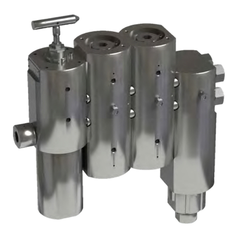
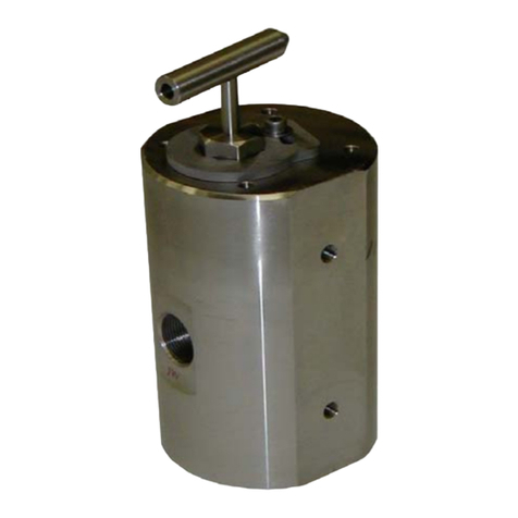
SkoFlo Industries BPR15000MFC-MA User manual

Pioneering an Industry
Surface Back Pressure Regulator
Medium Flow, Manual Operation
Operations and
Maintenance Manual
Industries
DOC-03704 Rev B
BPR15000MFC-MA

Surface Back Pressure Regulator BPR15000MFC-MA
Operations and Maintenance Instructions 1
TABLE OF CONTENTS
About SkoFlo ........................................................................................ 2
General Information........................................................................... 2
1. Product Overview ...................................................... 2
2. Guidelines for Using this Manual ........................ 2
3. Warning, Caution, Notice ....................................... 2
4. Abbreviations and Acronyms................................ 2
Installation & Maintenance............................................................. 3
5. Installation Procedures............................................ 3
6. Start-up Procedures.................................................. 3
7. Operation Notes and Warnings........................... 3
8. Maintenance Notes................................................... 4
9. Storage........................................................................... 4
10. Trouble Shooting Improper Valve
Performance............................................................................. 5
Appendix A – General Arrangement & Bill of Materials
(BOM)............................................................................................. 6
Appendix B – BOM – Primary Stage.........................................11
Appendix C – BOM – Pressure Stage.......................................12
Appendix D – BOM – Check Stage ...........................................13

Surface Back Pressure Regulator
BPR15000MFC-MA
Operations and Maintenance Instructions 2
ABOUT SKOFLO
Our experience and track record speak for themselves.
SkoFlo has delivered over 20,000 valves since 1988. We are
the only company that proves our products by testing in
surface applications before deploying them subsea. The
result is that SkoFlo valves have amassed over 25 million
continuous operating hours. This level of experience is
unparalleled and provides the basis for being the solution
provider to our served market.
SkoFlo Surface Back Pressure Regulator (BPR) is the
industry leader in the oil and gas marketplace and
regulating pump discharge pressure in chemical injection
systems.
GENERAL INFORMATION
1. Product Overview
The BPR is designed to maintain a constant set pressure in
pump discharge lines feeding the chemical injection
system. As pressure rises in the pump discharge line, the
BPR will maintain pressure levels at a Set Point while
allowing the unused fluid to return to the chemical
holding tank.
BPRs should be used in any pump discharge line where
the pressure must remain at a constant level and unused
fluid can be routed back to the fluid holding tank.
BPRs are not designed to be used as Pressure Safety
Devices.
BPRs provide a constant pressure to the system with
continuous spill-off to the chemical tank that is
independent of the flow rate. The BPR15000MFC series
has a maximum operating pressure of 15,000psi and
supports a flow range of 0.5 – 15 GPM.
2. Guidelines for Using this Manual
The following instructions are provided to ensure a safe
and proper installation.
−Read all instructions prior to installation and operation
of this product.
−Follow all warning and caution notes.
−Install this product as specified in the instructions
provided by SkoFlo.
−Prior to use, educate personnel in the proper
installation, operation, and maintenance of this
product.
−Only use replacement parts specified by SkoFlo.
3. Warning, Caution, Notice
Throughout this manual there are steps and procedures
which, if not followed, may result in a hazard. The
following flags are used to identify the level of potential
hazard.
! WARNING
WARNING IS USED TO INDICATE THE PRESENCE OF A
HAZARD WHICH CAN CAUSE SEVERE INJURY, DEATH, OR
SUBSTANTIAL PROPERTY DAMAGE IF THE WARNING IS
IGNORED.
! CAUTION
CAUTION IS USED TO INDICATE THE PRESENCE OF A
HAZARD WHICH CAN CAUSE INJURY OR PROPERTY
DAMAGE IF THE WARNING IS IGNORED.
! NOTICE
NOTICE IS USED TO NOTIFY PEOPLE OF INSTALLATION,
OPERATION, OR MAINTENANCE INFORMATION,
WHICH IS IMPORTANT BUT NOT HAZARD RELATED.
4. Abbreviations and Acronyms
BPR Back Pressure Regulator
BOM Bill of Materials
GA General Arrangement
MA Manual
NPT National Pipe Thread
PPE Personal Protective Equipment
PSI Pounds per Square Inch

Surface Back Pressure Regulator BPR15000MFC-MA
Operations and Maintenance Instructions 3
INSTALLATION &MAINTENANCE
5. Installation Procedures
Install the valve so that the flow is in the proper direction.
The "INLET" and "OUTLET" connections are indicated in
the general arrangement drawing in Appendix A. The
connections offered include the following:
−¾” MP – those connections are suitable for
Autoclave Engineers or Butech fittings.
−1” MP – those connections are suitable for
Autoclave Engineers or Butech fittings.
−Grayloc Hub 1GR5 (Short)
−Grayloc Hub 1GR7 (Long)
The "VENT" connection is not under pressure and will see
fluid only if the piston seal is leaking. This connection is
1/4" NPT and may be routed to a drain or atmospheric
container if desired. The "VENT" must remain free and
unrestricted, and should be visible.
The supply pump pulsations must be adequately
dampened with a pulsation dampener to avoid setting up
a resonant vibration in the SkoFlo valve.
6. Start-up Procedures
1. Open the supply isolation valve to the back-
pressure regulator slowly.
2. Turn the pressure adjustment handle clockwise
until you are at the desired pressure. Always start
at a pressure below the set pressure and increase
to the desired setting.
3. The BPR is now set and further adjustments aren't
required. Tighten the lock nut on the handle to
avoid inadvertent changes to the adjustment.
7. Operation Notes and Warnings
The SkoFlo Back Pressure Regulator has hard seats and is
not designed to provide complete "bubble-tight" shut off.
If tight shutoff is required, separate isolation valves should
be used for shutting off the flow. Overtightening the
handle will not further reduce flow. If the back pressure
does not increase when turning the handle clockwise. See
"Trouble Shooting Improper Valve Performance".
! WARNING
WEAR PROPER PERSONAL PROTECTIVE EQUIPMENT (PPE)
AS REQUIRED BY SITE SAFETY PERSONNEL WHEN
INSTALLING AND TESTING.
MAINTAIN SAFE WORKING DISTANCES AS DETERMINED
BY SITE SAFETY PERSONNEL WHEN TESTING.
CONSULT SKOFLO IF ANY PRODUCT CONCERNS ARISE
DURING HANDLING.
! CAUTION
DO NOT FLOW BACKWARDS THROUGH THE SKOFLO
VALVE. INTERNAL SEALS ARE DESIGNED FOR ONE
DIRECTION ONLY AND COULD POSSIBLY BECOME
DISLODGED.
! CAUTION
DO NOT ADJUST THE VALVE FROM OPEN TO CLOSED
POSITION UNLESS VALVE IS PRESSURIZED TO AVOID
THE POSSIBILITY OF DISLODGING THE STEM SEAL.
! NOTICE
INSTALL A PULSATION DAMPENER BETWEEN THE
PUMP DISCHARGE AND THE SKOFLO BACK PRESSURE
REGULATOR AS REQUIRED TO AVOID POSSIBLE
DAMAGE AND NOISE FROM HARMONIC PULSATIONS.
! NOTICE
INSTALL RELIEF VALVE AND/OR BURST PLATE
UPSTREAM OF THE SKOFLO BACK PRESSURE
REGULATOR AS REQUIRED.
! CAUTION
THE VENT FROM THE SPRING CHAMBER MUST NOT BE
BLOCKED. LEAVE OPEN TO ATMOSPHERE, OR ROUTE TO
A DRAIN COLLECTION POINT AT ATMOSPHERIC
PRESSURE. THIS VENT WILL ONLY HAVE FLUID IN THE
EVENT OF A LEAKING PISTON SEAL.
! NOTICE
WHEN LIFTING THE SKOFLO VALVE, LIFT USING
M12 X 1.75 EYEBOLTS IN SIDE OF BODY. DO
NOT LIFT USING THE HANDLE AS THIS CAN
DAMAGE THE HANDLE.

Surface Back Pressure Regulator
BPR15000MFC-MA
Operations and Maintenance Instructions 4
8. Maintenance Notes
Anytime that the valve is serviced, the pressure drop
across the primary stage must be verified and can be reset
by adjusting the Top Cap on the first Pressure Stage.
Refer to Appendix A & C for component details.
1. With valve at no inlet pressure:
−Install a 15,000 PSI gauges into Inlet and first
pressure stage test port (adjacent to inlet)
using 3/8" Autoclave fittings.
−Remove the Top Cap Lock Screw on the first
Pressure Stage.
−Tighten the Top Cap, then back it out if
necessary until a node lines up with the Lock
Screw hole.
2. Apply flow to the inlet at 7,000 -10,000 PSI.
3. Read the pressure differential between the 2
gauges. If the differential is less than 2500 PSI:
−Stop the flow to the valve, allowing all
pressure to drain.
−Back out the Top Cap ONE node ONLY.
! CAUTION
NEVER
OPEN
THE
TOP
CAP
MORE
THAN
4
NODES
FROM
TIGHTENED POSITION AND NEVER UNDER PRESSURE.
4. Repeat the flow test and readjust until the
differential is 2,500-3,500 PSI.
5. Replace the Top Cap Lock Screw and torque to 10-
foot pounds.
! CAUTION
WATCH
THE
WEEP
HOLE
IN
THE
SIDE
OF
THE
BODY
ADJACENT TO THE TOP CAP MOUNTING HOLES.IF FLUID
IS DETECTED,SHUT DOWN POWER IMMEDIATELY. THE
TOP CAP COULD BE OPEN TOO FAR OR THE SEAL IS
DAMAGED.
Replacing Seals: When replacing valve seals, it is
recommended that the new seals be lubricated with Parker
Super Lube or equivalent. Install backup ring on low
pressure side of O-ring. For more details, see seal kits
sheets (2) in Appendix C, D or E. Make sure the backup
ring is lined up at the joint.
Fastener & Torque Summary
NOTE: Loctite #271 requires heat (such as a propane
torch) to disassemble.
Recommended Spare Parts
9. Storage
When storing SkoFlo valves prior to first use, it is
recommended that the valves be stored indoors. If stored
outdoors, apply a light coating of protectant to the
exterior of the valve. The shipping plugs in the HP INLET,
RELIEF, and VENT should remain in place.
When storing SkoFlo valves after being in use, dismantle,
clean thoroughly and reassemble. Then store as noted
above.
Parts
Joined
Fastener
Description
Thread
Compound
Torque
Required
Cap Lock
Screws
M8 -25 SHCS
Grade 70 316SS
Never Seize
10 -12 FT LB
Tie Rod
Nuts
7/8 NC Teflon
Coated Nut
Never Seize
80-90 FT LB
In/Out
Adapters
Machined
Components
Never Seize
400-425 FT LB
Autoclave
Plugs
Machined
Components
Never Seize
20-25 FT LB
Holder
Machined
Components
Loctite #271
40-50 FT LB
Second Pin
Holder
Machined
Components
Loctite #271
40-50 FT LB
Description Part # Qty
Primary Stage Seat Holder with Seat
22048
1
Primary Stage Ceramic Pin
20544
1
Pressure Stage Ceramic Seat
20628
1
Check Stage Carbide Pin
20714 1
Complete Seal Kit EPDM:
22098
1
•
Primary Stage Seal Kit EPDM
22102
1
•
Pressure Stage Seal Kit EPDM 22104 3
•
Check Stage Seal Kit EPDM 22106 1
Complete Seal Kit FFKM: 22099 1
•Primary Stage Seal Kit FFKM
22103
1
•Pressure Stage Seal Kit FFKM
22105
3
•
Check Stage Seal Kit FFKM
22107
1

Surface Back Pressure Regulator BPR15000MFC-MA
Operations and Maintenance Instructions 5
10. Trouble Shooting Improper Valve
Performance

Surface Back Pressure Regulator BPR15000MFC-MA
Operations and Maintenance Instructions 6
APPENDIX A–GENERAL ARRANGEMENT &BILL OF MATERIALS (BOM)

Surface Back Pressure Regulator BPR15000MFC-MA
Operations and Maintenance Instructions 7

Surface Back Pressure Regulator BPR15000MFC-MA
Operations and Maintenance Instructions 8

Surface Back Pressure Regulator BPR15000MFC-MA
Operations and Maintenance Instructions 9

Surface Back Pressure Regulator BPR15000MFC-MA
Operations and Maintenance Instructions 10

Surface Back Pressure Regulator BPR15000MFC-MA
Operations and Maintenance Instructions 11
APPENDIX B–BOM –PRIMARY STAGE

Surface Back Pressure Regulator BPR15000MFC-MA
Operations and Maintenance Instructions 12
APPENDIX C–BOM –PRESSURE STAGE

Surface Back Pressure Regulator BPR15000MFC-MA
Operations and Maintenance Instructions 13
APPENDIX D–BOM –CHECK STAGE

SkoFlo Industries
14241 NE 200th Street
Woodinville, WA 98072 USA
Tel 1-425-485-7816
Fax 1-425-368-1696
www.skoflo.com
DOC-03704 Rev. B
Table of contents
Other SkoFlo Industries Controllers manuals
Popular Controllers manuals by other brands
Interpump Group
Interpump Group W3.0 operating instructions
salmson
salmson COFFRETS EC-DRAIN Installation and starting instructions

Bosch
Bosch Rexroth Indramat ECODRIVE DKC02.1 Series Project planning manual
Insta
Insta InstaLight Vario operating instructions
Auber Instruments
Auber Instruments WS-1500EPM Operation & instruction manual
Siemens
Siemens 91-HF Installation and service instruction
