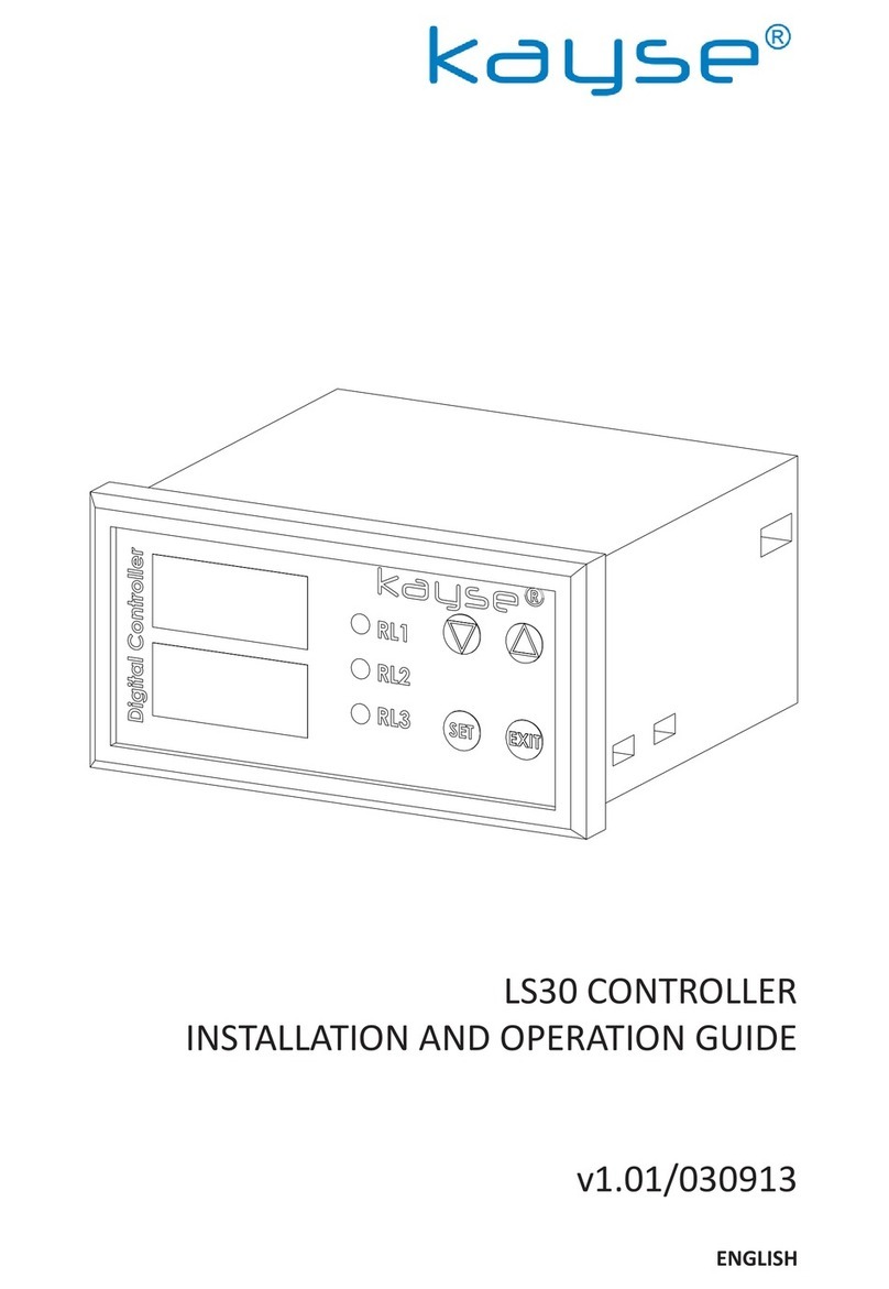
kayse LS20 Operating instructions

LS20 CONTROLLER
INSTALLATION AND OPERATION GUIDE
v1.00/051217
ENGLISH

LS20 CONTROLLER INSTALLATION AND OPERATING GUIDE
2
page
3
5
8
13
15
READ THIS DOCUMENT CAREFULLY BEFORE COMMISSIONING
THE DEVICE,
ELECTRICAL CONNECTION OF THE DEVICE MUST BE MADE BY
AUTHORIZED PERSONNEL OTHERWISE THERE IS DANGER OF
SERIOUS INJURY OR DEATH,
THIS DOCUMENT LATER SHOULD BE KEPT IN AN EASILY ACCES-
SIBLE PLACE,
ENERGY STRICTLY SHOULD NOT BE GIVEN TO THE DEVICE EX-
CEPT FOR CONNECTION SCHEMA AND TECHNICAL INFORMA-
TION GIVEN IN THIS GUIDE,
APPLICATIONS DEFINED IN THIS GUIDE AS INAPPROPRIATE CAN
TERMINATE WARRANTY OF PRODUCT,
IF YOU THINK THIS GUIDE IS NOT HELPFULL PLEASE CONTACT
US FROM OUR CONTACT INFORMATION,
•
•
•
•
•
•
INDEX
1. GENERAL
2. MOUNTING
3. ELECTRICAL CONNECTIONS
4. START UP
5. MALFUNCTION

LS20 CONTROLLER INSTALLATION AND OPERATING GUIDE 3
1. GENERAL
1.2 Block Diagram
1.1 Device Descripon
LS20 Controller devices are the devices that can control 3 dif-
ferent integrated relays by using data received from PS1x Limit
Switch series, PS3x Limit Switch series or LS20 Level Control
Equipments. With this data can be controlled motor, pump,
on-o valve, solenoid valve, audible or/illuminated alarm type
of three dierent devices by 3 each NO(Normally Open) +
NC(Normally Closed) relay contacts.
LS20 CONTROLLER
Logic Inputs Outputs
Relay 1 Dry Contact
Relay 2 Dry Contact
Relay 3 Dry Contact
Relay 1 Start
Relay 1 Stop
Relay 2 Start
Relay 2 Stop
Relay 3 Start
Relay 3 Stop

4
1.3 Technical Informaons
Logic Inputs
Relay Outputs
Supply
Power Consumpon
Working Temp.
Storage Temp.
: 6 Pieces Logical Signal Inputs
: 3 Pieces NO+NC Dry Contact Relay
Outputs (250 VAC / 3A max.)
: Standard 230 VAC (± %10)
Oponal 24 VDC (± %10)
: 2-3 W
: 0 +50 OC
: -40 +70 OC
1.4 Content of the Package
LS20 Controller is being shipped with terminal connecons, 2
each xing stands and this document in a carton box.
2. MOUNTING
2.1 Dimenons
LS20 CONTROLLER INSTALLATION AND OPERATING GUIDE

LS20 CONTROLLER INSTALLATION AND OPERATING GUIDE 5
2.2 Panel Cung Dimensions

LS20 CONTROLLER INSTALLATION AND OPERATING GUIDE
6
2.3 Assembly Environment and the Working Condions
LS20 Controller devices should be denitely used with at least
one panel protecon class IP65 or by installing within the box.
In contrary the oxidaon can occur in the electrical equipments.
Using of LS30 Controllers in medium of big evaporaon can not
be recommended from the point of life cycle.
ATTENTION : LS20 Controller should be denitely energized
while lling or draining the tank level because of needing trig-
ger to set or reset relays. In contrary it may cause overowing
or unexpected draining.
2.4 Mounng Type

LS20 CONTROLLER INSTALLATION AND OPERATING GUIDE 7
2.5 Assembly Sequencing
Place the device to the panel that has been manufactured ac-
cording to 2.2 Panel Cung Dimenons place the device by fac-
ing the screen yourself,
According to the 2.4 Mounng Type ghten the xing stands
within box by means of a suitable screw driver by installing the
side channels located at the sides of device,
In order to make the electricity connecon remove the termi-
nals at the a of device,
By means of a suitable screw driver make connecons as per 3.
Electrical Connecons,
3. ELECTRICAL CONNECTIONS
3.1 Basic Electrical Connecons
The electricity connecons of device should be made by an au-
thorized electrician. In addion cable connecons should be
maximum 1.5 mm2 in cross secon.
1
COM
11
2
ST ART1
12
Relay
Output(R1)
3
STOP1
13
4
START2
14
5 15
Relay
Output(R2) STOP2
6
START3
16
7
STOP3
17
8
9 19
Relay
Output(R3)
10
220V AC
POWER SUPPLY
50/60 Hz
20
•
•
•
•

LS20 CONTROLLER INSTALLATION AND OPERATING GUIDE
8
3.2 Supply Voltage Connecons
Energizing of device other than supply voltage tolerances may
severely damage the device. At connecon of devices with 220
VAC measures should be taken against electrical shock. At de-
vices with 24 VDC supply voltage, the direcons of -/+ poles
does not dierent.
L N
(General
Purpose
Fuse)
3 - 6A
220 VAC
220 VAC
POWER SUPPLY
50/60 Hz
+ -
(General
Purpose
Fuse)
3 - 6A
24 VDC
24 VDC
POWER SUPPLY

LS20 CONTROLLER INSTALLATION AND OPERATING GUIDE 9
3.3 Logic Input Connecons
In case of reversed operaon, the relay inputs 'start' and 'stop'
posions should be changed. For alarm applicaons. In alarm
applicaons, buon switch can be used instead of limit switch-
es for manual stop operaon. ('COM' and 'Stop' inputs).
3.3.1 PS10 / PS11 Limit Switches Connecons
1
2
3
4
5
6
7
8
9
10
11
12
13
14
15
16
17
19
20
START
STOP
LS20 CONTROLLER BACK SIDE

LS20 CONTROLLER INSTALLATION AND OPERATING GUIDE
10
3.3.2 PS30 / PS31 Limit Switches Connecons
1
2
3
4
5
6
7
8
9
10
11
12
13
14
15
16
17
19
20
START
STOP
LS20 CONTROLLER BACK SIDE

LS20 CONTROLLER INSTALLATION AND OPERATING GUIDE 11
3.3.3 LS20 Level Control Equipment Connecons
The drawing is given as example because LS20 Level Control
Equipments are manufactured according to requests.
1
2
3
4
5
6
7
8
9
10
11
12
13
14
15
16
17
19
20
LS20 CONTROLLER BACK SIDE
Common
Start
Stop
Level Control Equipment
LS20
Start
Stop

LS20 CONTROLLER INSTALLATION AND OPERATING GUIDE
12
3.4 Relay Output Connecons
Devices which draws heavy current and are coiled such pump
controlled by relay outputs, solenoid valve or siren should nec-
essarily be controlled in indirect way by means of auxiliary re-
lay and contactor. Otherwise, failure to do so may cause relay
contact to malfuncon or cause the device, which must be sup-
posed to work but due to the contacng point, to stop its op-
eraons and cause serious damage to the system (for example,
overows of tank).
NOT : It has been drawn by considering that all of equipments of con-
necon schemac are operang with 220 VAC power. According to dif-
ferent power values connecon way may vary.
1
2
3
4
5
6
7
8
9
10
11
12
13
14
15
16
17
19
20
LN
(General
Purpose
Fuse)
220 VAC
3 A
RELAY (or
Contactor)
LOAD
LS20 CONTROLLER BACK SIDE
Relay
Output(R1)
Relay
Output(R2)
Relay
Output(R3)220 VAC
POWER SUPPLY
50/60 Hz

LS20 CONTROLLER INSTALLATION AND OPERATING GUIDE 13
3.5 Cabling
Cable connecons should be maximum 1.5 mm2 cross secon.
Otherwise the clamp connecons may not be possibly done.
In general cabling, mul-wire and nned cables should be pre-
ferred to extend the operang life of the device and reduce the
possibility of contact failure caused by oxidaon. PS1x / PS3x
Limit Switch connecons to be made to logic inputs can use 2
x 0.75 mm2 cross-secon cables. LS20 Level Controllers must
be selected according to the number of contacts as they are
custom made specically for the applicaon.
4. START UP
The LS20 Controller can operate without any programming pro-
cess when the electrical connecons are made correctly. In the
screen, there are red - green LEDs only showing the operang
status of the output relays. In this way, the working and stopped
devices can be monitored.
Start Leds
o o
Sto
Leds

LS20 CONTROLLER INSTALLATION AND OPERATING GUIDE
14
LS20 Controllers' work logic is just to seal the output relays.
When the signal is received by "Start" input, the corresponding
relay is set and sealed and the connected device starts to work.
When the signal is received by “Stop” input, the relevant relay
is reset and sealing is broken and the connected device ends its
operaon.
LS20 Controllers must be energized when there is discharge or
lling at the tank, as they receive level informaon instantane-
ously. Otherwise, the level change may not be detected, so it may
be the case that the tank is overowed or discharged at an unde-
sirable amount.
LS20 Controllers can be energized aer the electrical connecons
are completed as per arcle "3. ELECTRICAL CONNECTIONS”. In
case that LS20 Controller devices and Limit Switches such as PS1x
/ PS3x other than LS20 Level Controllers will be used, it may be
necessary to send informaon to detect the level informaon af-
ter the inial power up. In the working scenario, aer the rst
energy is supplied;
If a device that needs to be run is not working, then apply an ex-
ternal magnet or the magnet side of water-gauge located in the
devices of Level Indicator of MLG Series into the “Start” or (for
example if solenoid valve does not funcon and in case that it is
controlled by the Relay 2 at LS20 Controller) into “Start 2” input
into the body of PS1x/PS3 in the manner almost to touch it;
check whether the device, that you wanted see working, does
work or not.
•

LS20 CONTROLLER INSTALLATION AND OPERATING GUIDE 15
In case that a device, which was not supposed work, is working;
then apply an external magnet or the magnet side of water-
gauge located in the devices of Level Indicator of MLG Series
into the “Stop” input or (for example if pump is working and in
case that it is controlled by the Relay 1 at LS20 Controller) “Start
1” input into the body of PS1x/PS3x Limit Switch in the manner
almost to touch it; check whether the device, that you do not
want to see it working, stop to work or not.
Once these operaons are done correctly, the LS20 Controller
will not have to be intervened again. In case of long-term en-
ergy interrupons, re-commissioning may be necessary.
•
5. MULFUNCTION
5.1 Mulfuncon Dedecon
In case that the device(s)
to be controlled did not
work even aer you made
the electric connecons of
LS20 Controller as per ar-
cle “3. ELECTRICAL CON-
NECTIONS”;
Please read carefully the arcle
“4. START UP” and make sure
that the device is to detect level
informaon correctly.
In case that the device(s)
to be controlled are work-
ing connuously even aer
you made the electric con-
necons of LS20 Controller
as per arcle “3. ELECTRI-
CAL CONNECTIONS”;
Please read carefully the arcle
“4. START UP” and make sure
that the device is to detect level
informaon correctly.

LS20 CONTROLLER INSTALLATION AND OPERATING GUIDE
16
In case that none
of the LEDs at
the screen does
not work even
aer you made
them energized;
Make sure that supply voltage reaches
to LS20 Controller. If the energy correctly
reaches to the Controller, LS20 may be out
of order. Pass through arcle 5.3.
In case that
devices con-
nected to the
LS20 Controller
even when the
level at the tank
changes;
Check the status of relays by means of Sta-
tus LEDs at the screen. Make sure that the
LED of Start connected to the malfuncon-
ing device is on.
In case that Stop LED is on;
• Tank level may not reach to the point of
start signal. Re-check the tank.
• Make sure that the sensor connecons of
logic input are made properly, addional
make a malfuncon diagnosis as per the
arcle 5.2.
In case that Start LED is on;
• Disconnect LS20 Controller from its pow-
er source. Remove the clamp of number 1
to 10 connected to the relay output. Take
measurements from clamps 2 & 3, 5 & 6,
9 & 10 at Ω of your measuring instrument.
For all measurements, you should read a
shortcut circuit (a resistance value close to
zero).The relays connected to the clamps
that cannot be assumed as shortcut may
be out of order. Proceed to the arcle 5.3.

LS20 CONTROLLER INSTALLATION AND OPERATING GUIDE 17
5.2 Determinaon of Sensor Defects
5.2.1 Determinaon of PS1x / PS3x Limit Switches Defects
There is no dierence between Limit Switches of PS1x and ve
PS3x Series in terms of their electrical structures. Only their
mechanical properes or their connecon types to the MLG
Series Level Indicators may vary. The PS1x and PS3x Series
Limit Switches are available with plug-in or cable connecons
(see "PS Series Limit & Bistable Switches Installaon and Op-
eraon Manual" for connecon and contact features).
Limit Switches only provide contact when they are at the same
point as the level amount. When the level is below or above
the level, the contact is in open-circuit posion. In order for a
test execuon to make, apply an external magnet or the mag-
net side of water-gauge located in the devices of Level Indica-
tor of MLG Series into the body of PS1x/PS3x Limit Switch in
the manner almost to touch it; A short circuit (a resistance
value near zero) must be read in Ω posion of the measuring
instrument. If the open circuit is read, the PS1x / PS3x Limit
Switches may be defecve. You can proceed to the arcle 5.3.

LS20 CONTROLLER INSTALLATION AND OPERATING GUIDE
18
5.2.2 Determinaon of LS20 Level Control Equipments De-
fects
LS20 Level Controllers also have a NO (Normally Open) con-
tact structure, such as PS1x and PS3x Series Limit Switches.
Tesng of the contacts is the control of switching the contacts
to the closed posion by moving the oat on the LS20 Level
Controller. When measurement is taken in Ω posion of the
measuring instrument, short circuit (near zero resistance val-
ue) must be read out by bringing the oat over the set contact
points in the factory.
More than one contact can be observed at a distance of 2-3
cm for the same contact. This situaon is related to contact
sensivity and this does not deem to indicate a failure.
LS20 Level Controllers do not have a standard test procedure
as they are custom built specic to the applicaon. for appli-
caon specic producon. The test should be performed tak-
ing the connecon diagram of the product into consideraon.
In case that these measurement values are not obtained, pro-
ceed to the arcle 5.3.

LS20 CONTROLLER INSTALLATION AND OPERATING GUIDE 19
Note the informaon regarding to the malfuncon,
Note the label informaon and serial number of the device,
Contact with the factory by using communicaon informaon
located at the back side of this Document.
5.3 Things To Be Done Before Service
In case that no soluon is found even if the trouble shoong has
been done as per the arcle “5.1”;
•
•
•

KAYSE END. MAM. SAN. TIC. A.S.
Tepeoren ITOSB 7th Street No:4 34959 Tuzla
ISTANBUL/TURKEY
Tel : +90 216 304 00 65 teknik@kayse.com.tr
Fax : +90 216 304 14 54 www.kayse.com.tr
Table of contents
Other kayse Controllers manuals
Popular Controllers manuals by other brands

SJE Rhombus
SJE Rhombus VFDC-4100 user manual

Ascon tecnologic
Ascon tecnologic KM5P Series Engineering manual

Buderus
Buderus Logamatic TC100 Installation and operating instructions

Weathermatic
Weathermatic smartline SL800 owner's manual

Samson
Samson 43-6 Mounting and operating instructions

Danfoss
Danfoss AMI 140 Series instructions