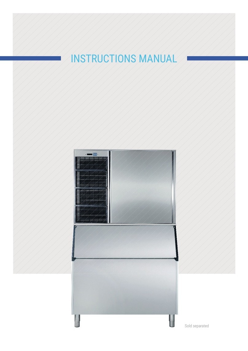
Skope ITV ICE QUEEN User manual

EN
ES
FR
DE
PO
IT
E
DA
NE
SV
BO
PO
PY
CE
TÜ
GRANULAR ICE
USER MANUALUSER MANUAL


English_IQ_3
THIS MANUAL IS PART OF THE PRODUCT. READ IT CAREFULLY IN ORDER TO USE AND
MAINTAIN THE EQUIPMENT CORRECTLY. IT IS IMPORTANT TO KEEP IT FOR FUTURE
TROUBLESHOOTING AND REFERENCE.
WARNING
The inallation of this equipment should be done by the Technical Assiance Service department.
The inlet jack should always be placed on an accessible location.
ALWAYS disconnect the power supply from the machine BEFORE any cleaning or maintenance
service.
Any change needed on the electrical inallation for the appropriate connection of the machine,
should be exclusively performed by qualied and certied professional personnel only.
Any use by the ice maker not intended to produce ice, using drinking water, is considered
inappropriate.
It is extremely dangerous to modify or intend to modify this machine, and shall make any type
warranty void.
This machine should not be used by children or handicapped without the proper supervision and
monitoring.
Children should be monitored to assure that they should not play near the equipment.
This machine is not intended to be used outdoors nor exposed to the rain.
Connect the equipment to the drinking water network.
The machine should be connected using the power cable supplied with the equipment. The
connection is not intended for xed cabling.
IT IS MANDATORY TO GROUND THE EQUIPMENT.
To avoid possible discharges on individuals or damages to the equipment, the machine
should be grounded pursuant local and/or national regulations as the case may be.
THE MANUFACTURER SHALL BE HELD HARMLESS IN CASE OF DAMAGES ARISING DUE
TO THE LACK OF THE GROUND INSTALLATION.
In order to assure the proper operation and eciency of this equipment, it is of paramount
importance to follow the recommendations of the manufacturer, SPECIALLY THOSE RELATED
TO CLEANING AND MAINTENANCE OPERATIONS, which should be performed moly by
qualied personnel only.
CAUTION:
Do not try to perform repairs. The intervention of non-qualied personnel, besides of being
dangerous, could result in serious malfunctioning. In case of damages, contact your diributor.
We recommend to always use original replacement and spare parts.
Perform all discharge and recovery of materials or wae according the national regulations in
force.
EN

English_IQ_4
1| RECEPTION OF THE MACHINE
Inspect the outside packing. In case of damages, MAKE THE CORRESPONDING CLAIM TO
THE CARRIER.
To conrm the exience of damages, UNPACK THE MACHINE IN THE PRESENCE OF THE
CARRIER and ate any damage on the equipment on the reception document, or on a separate
inrument. As from May 1, 1998, we complie with the European regulations on management of
packing and packing wae, inserting the “Green Dot Label” on all their packages.
Always ate the machine number and model. This number is printed on three locations:
1.1 PACKING
On the outside, it contains a label with the manufacturing number (1).
1.2 EXTERIOR OF THE EQUIPMENT
On the back of the equipment, there appears a label
with the same characteriics as the previous one (1).
1.3 NAMEPLATE
On the back of the machine.
Check that in interior of the machine the
inallation kit is complete and comprises:
- ¾ gas pipe, lters and manual.
- 22 mm drain hose in models 45 and 85
and in water cooled machines
- In some models, shims are included.
- Warranty and serial number.
SHOULD BE KEPT OUTSIDE THE REACH OF CHILDREN, AS THEY ARE A SOURCE OF
POTENTIAL HAZARD.
2| INSTALLATION
THIS ICE MAKER IS NOT DESIGNED FOR OUTDOOR OPERATION.
CAUTION:
The machines are designed to operate at room temperature between 5ºC (41ºF) and 43ºC
(109.40ºF), with inlet water temperature between 5ºC (41ºF) and 35ºC (95ºF).
The reduction motor is excessively forced if operated under the minimum temperatures. Above the
maximum temperature, the life of the compressor is shortened and the production is subantially
less.
Do not place anything over the maker or facing the front louver.
(1)

English_IQ_5
In case the front louver is not enough, the exit is either total or partially obructed or due to its
placement it will receive hot air from another device, we recommend, in case it is not possible to
change the location of the machine, TO INSTALL A WATER CONDENSER.
IT IS IMPORTANT THAT THE WATER PIPING DO NOT PASS BY OR NEAR SOURCES OF
HEAT SO AS NOT TO LOSE ICE PRODUCTION.
THREAD THE SUPPORT LEGS TO THE BASE OF THE MACHINE ON THE HOUSING SET TO
SUCH END AND REGULATE THE HEIGHT AS TO HAVE THE EQUIPMENT PERFECTLY
LEVELED.
2.1 WATER AND DRAINAGE
Water quality has a remarkable inuence on the appearance, hardness
and avour of the ice as well as, on the machines condensate by water,
on the life of the condenser.
2.2 CONNECTIONS TO THE WATER NETWORK
Use a exible pipe (1.3 m – 4.27 feet length) with the two lter joints
supplied with the machine. We rongly discourage the use of two-exit
bibs and two switches as, due to an error could close that back one,
leaving the machine without water supply. This could result on a
damage call without actually exiing one.
Pressure should be eablished between 0.7 and 6 Bar (10 / 85 psi.)
If pressures overpass such values, inall the necessary corrective
devices.
IN MODULAR MACHINES
Base jack
Bib
Discharge hose
Water connection hose
Jack
Ventilation louver
>4”
>10 cm
Jack Base jack
Bib
Silo drainage
Water connection hose
Condenser discharge outlet
>4”
>10 cm

English_IQ_6
2.4 ELECTRICAL CONNECTION
IT IS MANDATORY TO GROUND THE EQUIPMENT.
To avoid possible discharges on individuals or damages to the equipment, the machine
should be grounded pursuant local and/or national regulations as the case may be.
THE MANUFACTURER SHALL BE HELD HARMLESS IN CASE OF DAMAGES ARISING DUE
TO THE LACK OF THE GROUND INSTALLATION.
The machine is supplied with a 1.5 m (4.92 feet) cable of length. In case the supply cable is
damaged, it should be replaced by a cable of special assembly to be furnished by the manufacturer
or po-sale service. Such replacement should be performed by qualied technical service only.
The machine should be places in such a way as to allow a minimum space between the back and
the wall to allow an easy access and without risks to the cable jack.
Safeguard the base of the jack.
It is convenient to inall adequate switches and fuses.
The line up to the jack should have a minimum section of 2.5 mm2 (0.0038 in2)
2.3 CONNECTION TO DRAINAGE
Drainage should be located lower to the machine level, at 150 mm (5.91 inches) minimum.
It is convenient that the drainage pipe is of 30 mm (1.18 in) of interior diameter and with a minimum
gradient of 3 cm (1.18 in) per meter (see gure).
CORRECT
DESCENDING
INCORRECT INCORRECT
ASCENDING ASCENDING
AFVOERlLIJN
Modular makers should be inalled over deposits or silos, following
the inructions contained in this manual.
The resiance and ability of the container-machine/s assembly
should be veried, as well as the faening elements.
2.5 INSTALLATION OF MODULAR EQUIPMENTS OVER DEPOSITS OR SILOS

English_IQ_7
2.7 WATER LEVEL
The function of the water level is to maintain the necessary ow on the evaporator, and using the
magnetic micro device incorporated, op the operation of the machine until the water reaches
again the container. The models 400, 550 and 1100 have a water pressoat replacing the micro-
magnetic.
The optimum level is located on the horizontal indicated in the gure, and its regulation is made
following the indications appearing below.
2.6 ASSEMBLY OF THE DISPERSION CONE*
This device diributes the ice in the silos, and avoids ice compression
under the exit pipe.
Changing its position, the ice could be directed to any direction.
*NOT INCLUDED
FLOAT VALVE REGULATION
FLOAT
PROBE
SAFETY OVERFILL Turn upwards to increase the level,
and downwards to decrease it.
(Grab from the metallic arm, NEVER
FROM THE FLOAT)

English_IQ_8
NOTE: In case input water pressure is higher that 6 Bar (85 psi), inall a pressure reducer. THE
BIBB CONNECTION PRESSURE SHOULD NEVER BE REDUCED.
Once the inallation inructions are followed (ventilation, site conditions, temperatures, water
quality, etc.), proceed as follows:
1. In the case of modular modules, remove the cover to access the inallation kit (lters,
connection hoses, dispersion cones, etc.).
2. In case of compact models, open the deposit door to access the inallation kit.
3. Open the water inlet. Verify the exience of leakages.
4. Connect the machine to the electrical network.
5. Verify that there are no vibrations or frictions on the elements.
6. After the 10 minutes of the timer inalled in the electric panel, the machine will art the
operation.
7. In the case of modular models (mainly in three-phase equipments), having the cover removed,
verify that the motor is rotating in the correct direction.
8.Verify that after 15 minutes, the fro on the aspiration pipe is at 20 mm (0.78 in) of the compressor.
CAUTION:
INSTRUCT THE USER ABOUT MAINTENANCE, INFORMING THAT MAINTENANCE AND
CLEANING OPERATION ASWELLASDAMAGESDUETO THELACKOFSUCHOPERATIONS:
ARE NOT INCLUDED ON THE WARRANTY.
The technical inaller shall invoice traveling cos, hours and materials used on such operations.
MINIMUM 10 psi (0,7 Bar)
MAXIMUM 85 psi (6 Bar)
3.1 PREVIOUS CHECKUP
a) Is the machine leveled?
b) Voltage and frequency are the same as those on the nameplate?
c) Are the discharges connected and operating?
d) ** If air condensed: Is the air circulation and its temperature appropriate?
e) ** Is water pressure appropriate?
MAXIMUM 43ºC / 109,40ºF 35ºC / 95ºF
MINIMUM 5ºC / 41ºF 5ºC / 41ºF
ROOM WATER

English_IQ_9
4 | MAINTENANCE AND CLEANING INSTRUCTIONS
CAUTION: Maintenance and cleaning operations and damages as the lack of those activities: Are
not included on the warranty.
If a good maintenance is performed, the machine will continue producing a good quality ice and
will be free of damages.
Maintenance and cleaning intervals will depend on the conditions of the location and water quality.
CAUTION: At lea, one revision and cleaning should be performed every six months.
On duy environments, it might be necessary to clean the condenser on a monthly basis.
4.1 MAINTENANCE AND CLEANING PROCEDURES:
** CAUTION: For all cleaning and maintenance operations: Disconnect the machine from the
power supply.
1. Water condenser
1. Disconnect the machine.
2. Disconnect the water inlet or close the bib.
3. Disconnect the water inlet and outlet from the condenser.
4. Prepare a solution at the 50% of phosphoric acid and diilled or demineralized water.
5. Make the solution circulate through the condenser. (The solution is more eective if hot –
between 35ºC [95ºF] and 40ºC [104ºF]).
DO NOT USE HYDROCHLORIC ACID.
2. Air Condenser
1. Disconnect the machine.
2. Disconnect the water inlet or close the bib.
3. Clean the louvered area with the help of an aspirator with a brush, non-metallic brush or low-
pressure air.
1. Disconnect the machine, close the water and empty the ice-cube ock.
2. Use a dishcloth and bleach with detergent.
Use the same procedure as the one indicated for the container.
They are easily obructed during the r days of operation, MAINLY WITH NEW PIPING
INSTALLATIONS.
Loose the hose and clean it under water.
6. Water Leak Control
When working on the machine, always check the water connections, atus of the clamps and
hoses with the purpose of avoiding leakages and prevent damages or oods.

English_IQ_10
ESTE MANUAL FORMA PARTE DEL PRODUCTO. LEA DETENIDAMENTE ESTE
DOCUMENTO PARA UN CORRECTO USO Y MANTENIMIENTO DEL EQUIPO. ES
IMPORTANTE SU CONSERVACION PARA POSIBLES CONSULTAS POSTERIORES.
ADVERTENCIAS
La inalación de ee aparato debe ser realizada por el Servicio de Asiencia Técnica.
La clavija de toma de corriente debe quedar en un sitio accesible.
Desconectar SIEMPRE la maquina de la red eléctrica ANTES de proceder a cualquier operación
de limpieza o manutención.
Cualquier modicación que fuese necesaria en la inalación eléctrica para la perfecta conexión
de la máquina, deberá ser efectuada exclusivamente por personal profesionalmente cualicado y
habilitado.
Cualquier utilización del productor de cubitos que no sea el de producir hielo, utilizando agua
potable, es considerado inadecuado.
Modicar o tratar de modicar ee aparato, además de anular cualquier forma de garantía, es
extremadamente peligroso.
El aparato no debe ser utilizado por niños pequeños o personas discapacitadas sin supervisión.
Los niños pequeños deben ser vigilados para asegurar que no juegan con el aparato.
Conectar a la red de agua potable.
La máquina se debe conectar mediante el cable de alimentación suminirado con la misma. No
eá previa para ser conectada a una canalización ja.
ESTE APARATO DEBE CONECTARSE OBLIGATORIAMENTE A TIERRA.
Para evitar posibles descargas sobre personas o daños al equipo, se bede conectar el
EL FABRICANTE NO SERA CONSIDERADO RESPONSABLE ANTE DAÑOS CAUSADOS
POR LA FALTA DE PUESTA A TIERRA DE LA INSTALACION.
Para garantizar la eciencia de ea maquina y su correcto funcionamiento, es imprescindible
ceñirse a las indicaciones del fabricante, SOBRE TODO EN LO QUE CONCIERNE A LAS
OPERACIONES DE MANTENIMIENTO Y LIMPIEZA, que en la mayor parte de los casos deberá
efectuarlas personal cualicado.
ATENCIÓN:
No tratar de repararlo por uno mismo. La intervención de personas no cualicadas, además de ser
peligrosa, puede causar graves desperfectos. En caso de avería, contactar con el diribuidor que
se lo ha vendido. Le recomendamos exigir siempre repueos originales.
Realizar la descarga y recuperación de los materiales o residuos en base a las disposiciones
nacionales vigentes en la materia.
ES

Español_IQ_11
1| RECEPCIÓN DE LA MÁQUINA
Inspeccionar exteriormente el embalaje. Si se ve roto o dañado, RECLAMAR AL TRANSPORTISTA.
Para concretar si tiene daños la máquina, DESEMBALARLA EN PRESENCIA DEL
TRANSPORTISTA y dejar conancia en el documento de recepción, o en escrito aparte, los
daños que pueda tener la máquina. Desde el día 1 de mayo de 1998 cumplimos con las normativas
europeas sobre la geión de Envases y residuos de Envases, colocando el diintivo punto
verde en los embalajes.
Hacer conar siempre el número de la máquina y modelo. Ee número ea impreso en tres
sitios:
1.1 EMBALAJE
Exteriormente lleva una etiqueta con el número de fabricación (1).
1.2 EXTERIOR DEL APARATO
En la parte trasera, en una etiqueta igual a la anterior (1).
1.3 PLACA DE CARACTERÍSTICAS
En la parte trasera de la máquina.
Vericar que en el interior de la máquina se encuentra
completo el KIT de inalación, compueo por:
- Acometida ¾ gas, ltros y manual.
- Manguera de desagüe (22 mm) en los modelos 45 y 85
y en las máquinas condensadas por agua.
- En algunos modelos, suplemento de las patas.
- Garantía y número de serie
UNA POTENCIAL FUENTE DE PELIGRO.
2| INSTALACIÓN
ESTE FABRICADOR DE HIELO NO ESTÁ DISEÑADO PARA FUNCIONAR EN EL EXTERIOR.
ATENCIÓN:
Las máquinas eán previas para funcionar con temperatura ambiente entre 5ºC y 43ºC, (41ºF
y 109ºF) y con temperaturas de entrada de agua comprendidas entre 5ºC y 35ºC (41ºF y 95ºF).
Por debajo de las temperaturas mínimas se fuerza en exceso el motor reductor. Por arriba de las
máximas la vida del compresor se acorta y la producción disminuye considerablemente.
No colocar nada sobre el fabricador ni frente a la rejilla delantera.
(1)

Español_IQ_12
Si la toma de aire delantera es insuciente, la salida queda obruida total o parcialmente, o si por
su colocación va a recibir aire caliente de otro aparato, aconsejamos encarecidamente, en caso
de no poder cambiar el emplazamiento de la máquina, INSTALAR UNA CONDENSADA POR
AGUA. ES IMPORTANTE QUE LA TUBERÍA DE ACOMETIDA DEL AGUA NO PASE POR O
CERCA DE FOCOS DE CALOR PARA NO PERDER PRODUCCIÓN DE HIELO.
ROSCAR LAS PATAS A LA BASE DE LA MÁQUINA EN LOS ALOJAMIENTOS DISPUESTOS
PARA TAL FIN Y REGULAR SU ALTURA DE MODO QUE EL EQUIPO QUEDE
PERFECTAMENTE NIVELADO.
EN MÁQUINAS MODULARES
Base enchufe
Grifo
Manguera desagüe
Manguera acometida agua
Clavija enchufe
Rejilla de ventilación
>4”
>10 cm
Clavija enchufe Base enchufe
Grifo
Desagüe silo
Manguera acometida agua
Desagüe salida condensador
>4”
>10 cm
2.1 AGUA Y DESAGÜE
La calidad del agua inuye notablemente en la apariencia, dureza y
sabor del hielo, y en las condensadas por agua en la vida del
condensador.
2.2 CONEXIÓN A LA RED DE AGUA
Utilizar la acometida exible (largo 1,3 m.) con las dos juntas ltro
suminiradas con la máquina. Desaconsejamos la utilización de los
grifos con dos salidas y dos llaves ya que por error pueden cerrar el
trasero con lo que la máquina se queda sin agua. Eo puede
acarrear la llamada por avería sin exiir éa.
La presión debe ear comprendida entre 0,7 y 6 Bar. (10 / 85 psi.)
Si las presiones sobrepasan eos valores inalar los elementos
correctores necesarios.

Español_IQ_13
2.3 CONEXIÓN AL DESAGÜE
El desagüe debe encontrarse más bajo que la máquina, como mínimo 150 mm.
El tubo de desagüe conviene que tenga un diámetro interior de 30 mm. y con una pendiente
mínima de 3 cm. por metro (véase la gura)
CORRECTO
DESCENDENTE
INCORRECTO
ASCENDENTE
INCORRECTO
2.4 CONEXIÓN ELÉCTRICA
ESTE APARATO DEBE CONECTARSE OBLIGATORIAMENTE A TIERRA.
Para evitar posibles descargas sobre personas o daños al equipo, se bede conectar el
EL FABRICANTE NO SERA CONSIDERADO RESPONSABLE ANTE DAÑOS CAUSADOS
POR LA FALTA DE PUESTA A TIERRA DE LA INSTALACION.
La máquina se suminira con un cable de 1,5 m. de longitud. Si el cable de alimentación eá
dañado, debe ser suituido por un cable o conjunto especial a suminirar por el fabricante o el
servicio poventa. Dicha suitución debe ser realizada por el servicio técnico cualicado.
Se deberá colocar la máquina de tal manera que se deje un espacio mínimo entre la parte poerior
y la pared para permitir la accesibilidad a la clavija del cable de manera cómoda y sin riesgos.
Prevenir la oportuna base de enchufe.
Es conveniente la inalación de un interruptor y de los fusibles adecuados.
La línea haa la base del enchufe deberá tener una sección mínima de 2.5 mm2
2.5 INSTALACIÓN DE EQUIPOS MODULARES SOBRE DEPÓSITOS O SILOS.
Los fabricadores modulares deben inalarse sobre depósitos o
silos, siguiendo las indicaciones contenidas en ee manual.
Se debe vericar la resiencia y eabilidad del conjunto recipiente-
máquina/s, así como la jación de los elementos.

Español_IQ_14
2.6 MONTAJE DEL CONO DE DISPERSIÓN* (MODELOS
Ee accesorio reparte el hielo en los silos, y evita que se apelmace
debajo del tubo de salida.
Variando su posición puede dirigirse el hielo en cualquier dirección.
*NO INCLUIDO
2.7 NIVEL DEL AGUA
La función del nivel del agua es mantener el ujo necesario de éa en el evaporador y, con el
micro magnético que incorpora, parar el funcionamiento de la máquina haa que el agua llegue
de nuevo a la cubeta. Los modelos 400, 500 y 1100 incorporan un presoato de agua en
suitución del micro magnético.
El nivel óptimo se encuentra en la horizontal que señala la gura, y su regulación se hace siguiendo
las indicaciones de la misma.
Doblar hacia arriba para subir el nivel
y hacia abajo para descenderlo
(coger sólo por el brazo metálico
NUNCA POR LA BOYA)
REGULACIÓN DE LA VÁLVULA DE FLOTADOR
BOYA
SONDA
REBOSADERO SEGURIDAD

Español_IQ_15
3| PUESTA EN MARCHA
3.1 COMPROBACIÓN PREVIA
a) ¿Eá la máquina nivelada?
b) ¿Es el voltaje y la frecuencia igual al de la placa?
c) ¿Eán los desagües conectados y funcionan?
d) ** Si es condensada por aire: ¿La circulación de ee y la temperatura del local son las
adecuadas?
MÍNIMA 10 psi (0,7 Bar)
MÁXIMA 85 psi (6 Bar)
MAXIMUM 43ºC / 109,40ºF 35ºC / 95ºF
MINIMUM 5ºC / 41ºF 5ºC / 41ºF
AMBIENTE AGUA
e) ** La presión de agua es la adecuada?
NOTA: Si la presión de entrada de agua es superior a 6 Bar (85 psi) inalar un reductor de
presión, NUNCA SE DEBE REDUCIR LA PRESION DEL GRIFO DE ACOMETIDA.
3.2 PUESTA EN MARCHA
Una vez seguidas las inrucciones de inalación (ventilación, condiciones del local, temperaturas,
calidad de agua etc.) proceder como sigue:
1. En los modelos modulares, retirar la cubierta superior para acceder al kit de inalación
(ltros, mangueras de acometida, cono de dispersión, etc...)
2. En los modelos compactos, abrir la puerta del depósito para acceder al kit de inalación.
3. Abrir la llave de paso de agua. Comprobar que no hay fugas.
4. Conectar la maquina a la red eléctrica.
5. Comprobar que no hay ningún elemento que roce o vibre.
6. Pasados los 10 minutos del temporizador inalado en el cuadro eléctrico, la máquina se
pondrá en funcionamiento.
7. En los modelos modulares (fundamentalmente en los equipos trifásicos), con la cubierta
superior quitada, comprobar que el giro del motor es en sentido correcto.
8. Comprobar que tras 15 minutos, la escarcha en el tubo de aspiración se queda a unos 20 mm
del compresor.
ATENCIÓN: INSTRUIR AL USUARIO SOBRE EL MANTENIMIENTO, HACIÉNDOLE SABER
QUE LAS OPERACIONES DE MANTENIMIENTO Y LIMPIEZA Y LAS AVERÍAS PRODUCIDAS
POR SU OMISIÓN: NO ESTÁN INCLUIDAS EN LA GARANTÍA.
El inalador facturara los viajes, tiempo y materiales empleados en eas operaciones.

Español_IQ_16
4| INSTRUCCIONES DE MANTENIMIENTO Y LIMPIEZA
ATENCIÓN: Las operaciones de mantenimiento y limpieza, y las averías producidas por su
omisión: No eán incluidas en la garantía.
Solamente si se efectúa un buen mantenimiento, la máquina seguirá produciendo buena calidad
de hielo y eará exenta de averías.
Los intervalos de mantenimiento y limpieza dependen de las condiciones del local de
emplazamiento y de la calidad del agua.
ATENCIÓN: Como mínimo una revisión y limpieza deberá hacerse cada seis meses.
En lugares muy polvorientos, la limpieza del condensador puede ser necesaria efectuarla cada
mes.
4.1 PROCEDIMIENTOS DE MANTENIMIENTO Y LIMPIEZA:
** ATENCIÓN: Para las operaciones de limpieza y mantenimiento: desconectar la máquina de la
corriente eléctrica excepto en la limpieza de la cuba de fabricación.
1. Condensador de agua
1. Desconectar la máquina.
2. Desconectar la entrada de agua o cerrar el grifo.
3. Desconectar la entrada y salida de agua del condensador.
4. Preparar una solución al 50% de ácido fosfórico y agua deilada o desmineralizada.
5. Hacerla circular por el condensador. (La mezcla es más efectiva con agua caliente - entre
35ºC [95ºF] y 40º C [104ºF] -) NO UTILIZAR ÁCIDO CLORHÍDRICO.
2. Condensador de aire
1. Desconectar la máquina.
2. Desconectar la entrada de agua o cerrar el grifo.
3. Limpiar la zona aleteada con ayuda de un aspirador provio de cepillo, brocha no metálica o
aire a baja presión.
1. Desconectar la maquina, cerrar el agua y vaciar el ock de hielo.
2. Utilizar una bayeta de cocina y detergente.
Utilizar el mismo procedimiento que con la cuba de ock.
Suelen obruirse los primeros días de ear la máquina en marcha, SOBRE TODO CON LAS
INSTALACIONES DE FONTANERÍA NUEVAS. Soltar la manguera y limpiarlos bajo el grifo del
agua.
Siempre que se intervenga en la máquina revisar todas las conexiones de agua, eado de las
abrazaderas y mangueras con el n de no dejar fugas y prevenir roturas e inundaciones.

Française_IQ_17
FR
UN CORRECT USAGE ET ENTRETIEN DU PRODUIT. CONSERVEZ CE MANUEL POUR
TOUTE CONSULTATION ULTERIEURE.
AVERTISSEMENTS
Cet appareil doit être inallé par le Service d’Assiance Technique.
L’interrupteur de la prise électrique doit être inallé dans un endroit accessible.
Débrancher TOUJOURS l’appareil du réseau électrique AVANT de procéder aux opérations de
nettoyage ou d’entretien.
Toute modication à eectuer au niveau de l’inallation électrique pour mieux inaller l’appareil,
doit être conée à un technicien qualié.
L’utilisation de l’appareil pour tout dein autre que la fabrication de glaçons en utilisant de l’eau
potable, e considérée incorrecte.
Les modications eectuées à l’appareil (même à titre d’essai), au-delà de faire tomber la garantie,
peuvent résulter extrêmement dangereuses.
Cet appareil ne doit pas être utilisé par des enfants ou des personnes handicapées sans
surveillance.
Ne pas permettre aux enfants de jouer avec l’appareil.
Ne pas utiliser l’appareil à l’extérieur. Ne pas exposer l’appareil à la pluie.
Raccorder l’appareil au réseau d’eau potable.
Utiliser uniquement le câble d’alimentation électrique fourni avec l’appareil. Il n’e pas prévu la
connexion directe de l’appareil à une canalisation xe.
CET APPAREIL DOIT OBLIGATOIREMENT ETRE MIS A LA TERRE.
LE FABRICANT NE PEUT ETRE RETENU RESPONSABLE DES DOMMAGES CAUSES PAR
An d’assurer l’ecacité de l’appareil, il faut suivre les inructions du fabricant, NOTAMMENT EN
CE QUI CONCERNE LES OPERATIONS DE NETTOYAGE ET D’ENTRETIEN, lesquelles devront
être par la plupart eectuées par un technicien qualié.
AVERTISSEMENT:
Ne pas essayer de réparer l’appareil soi-même. Toute réparation doit être eectuée par un
technicien qualié. En cas de défaut, adressez-vous au revendeur. Veuillez toujours exiger la
provision de pièces de rechange originelles.
Eectuer le déballage et récupération des matériaux selon les dispositions nationales en vigueur.

Française_IQ_18
Vérier la partie externe de l’emballage. Si le carton e endommagé, VEUILLEZ RECLAMER AU
TRANSPORTEUR.
Pour conater si l’appareil e endommagé, DEBALLER L’APPAREIL DEVANT LE
TRANSPORTEUR et rendre compte sur le document de réception de l’appareil -ou en document
séparé- les dommages qui puissent avoir subi l’appareil. Depuis le 1º mai 1998 nous marquons
ses emballages d’un “Point Vert” conformément aux normes européennes relatives aux
emballages et déchets d’emballages.
Marquer toujours le numéro de l’appareil et son modèle. Ce numéro e marqué à trois endroits
diérents :
1.1 EMBALLAGE
A l’extérieur de l’emballage se trouve une étiquette avec le numéro de fabrication (1).
A l’arrière se trouve une étiquette identique (1).
1.3 PLAQUE DE CARACTÉRISTIQUES
Située a l’arriere de la machine
Vérier que le KIT d’inalation se trouve a
l’intérieur de l’appareil. Celui-ci e composé de:
- Tuyau d’alimentation ¾ po, ltres et manuel.
- Tuyau de drainage de 22 mm en modèles 45 et 85
et en machines condensées par eau.
- Sur certains models, pieds de nivellement.
- Garantie et numéro de série.
ÊTRE LAISÉS À LA PORTÉE DES ENFANTS.
2 | INSTALLATION
AVERTISSEMENT:
Les machines sont conçues pour travailler avec un rang de température ambiante se situant entre
5ºC et 43ºC (41ºF et 109ºF), et des températures d’entrée d’eau situées entre 5ºC et 35ºC (41ºF
et 95ºF).
Par dessous des températures minimales le moteur de réduction travaille excessivement forcé.
(1)

Française_IQ_19
Par-dessus des températures maximales la vie du compresseur se raccourcie et la production de
glaçons diminue considérablement.
Ne rien placer sur l’appareil ni devant les fentes de ventilation.
Si l’entrée d’air par avant e insusante, ou la sortie d’air ree totale ou partiellement couverte,
ou bien comme conséquence de recevoir de l’air chaud d’un autre appareil, dans le cas où
l’appareil ne pourrait pas être replacé, nous conseillons
Prise murale
Robinet
Tuyau de vidange
Tuyau d’entrée d’eau
Fiche electrique
Febtes de Ventilación
>4”
>10 cm
Fiche electrique Prise murale
Robinet
Vidange réservoir
Tuyau d’entrée d’eau
Tuyau de vidange
>4”
>10 cm
INSTALATION DES MACHINES MODULAIRES
2.1 ALIMENTATION EN EAU ET VIDANGE
La qualité de l’eau e très importante pour l’aspect, la dureté et le goût
de la glace. Dans le cas des appareils condensés par eau, ceci e en
relation avec la vie du condensateur.
Utiliser le tuyau exible (1,3m) avec les deux écrous-ltres fournis avec
l’appareil. Nous déconseillons l’utilisation de robinets doubles, du fait
qu’on peut arriver à couper la provision d’eau de manière involontaire.
Ceci peut entraîner des visites du SAV sans motif.
La tension devrait être comprise entre 0,7 et 6 Bar (10 / 85 psi.)
Si les tensions vont dépasser ces valeurs indiquées, inaller les
éléments de correction nécessaires.

Française_IQ_20
2.4 CONNEXION ÉLECTRIQUE
CET APPAREIL DOIT OBLIGATOIREMENT ETRE MIS A LA TERRE.
LE FABRICANT NE SERA DONC PAS RESPONSABLE DES DOMMAGES CAUSES PAR LE
L’appareil e fourni avec un câble d’alimentation de 1,5 m. de long. Si le câble d’alimentation e
endommagé, il faut le remplacer par un câble ou ensemble qui devra être fournie par le fabriquant
ou par le Service Après Vente. Ce remplacement devra être eectué par un service technique
qualié.
Il e recommandé de placer l’appareil de manière à laisser un espace minimal entre le panneau
arrière de l’appareil et le mur, permettant l’accès à la che du câble d’alimentation de manière
aisée et sans risque.
Prévoir une prise électrique appropriée.
Il e recommandé de prévoir l’inallation d’un interrupteur ainsi que des fusibles appropriés.
La ligne jusqu’à la base de la prise électrique doit avoir un diamètre minimal de 2.5 mm2
indiquée dans la plaque, peuvent entraîner des dommages ou empêcher le démarrage de
2.3 RACCORDEMENT AU DRAIN DE VIDANGE
Le drain de vidange doit être situé plus bas que l’appareil, 150 mm minimum.
Il e recommandé que le tuyau de vidange soit d’un diamètre intérieur de 30 mm. avec une pente
minimale de 3 cm. par mètre (voir images).
CORRECT
DESCENDENT
INCORRECT INCORRECT
ASCENDENT
2.5 INSTALATION DE MACHINES MODULAIRES SUR DES
Les machines à glaçons peuvent être inallées sur des dépôts, suivant
les inructions du manuel.
Il faut vérier la résiance et la abilité de l’ensemble dépôt - machine à
glaçons, ainsi que les xations des éléments.
Table of contents
Languages:
Other Skope Ice Maker manuals

