5 Trouble Shooting Instructions
If the motor will not run, set the switch (B) to MAN and try to operate the motor via switch (C). If successful,
check the opening and closing connections to the automatic unit and the potentiometer, if necessary. If not
successful, check that 230 V ac is being supplied. If so, set switch (C) to open position (upwards), remove the
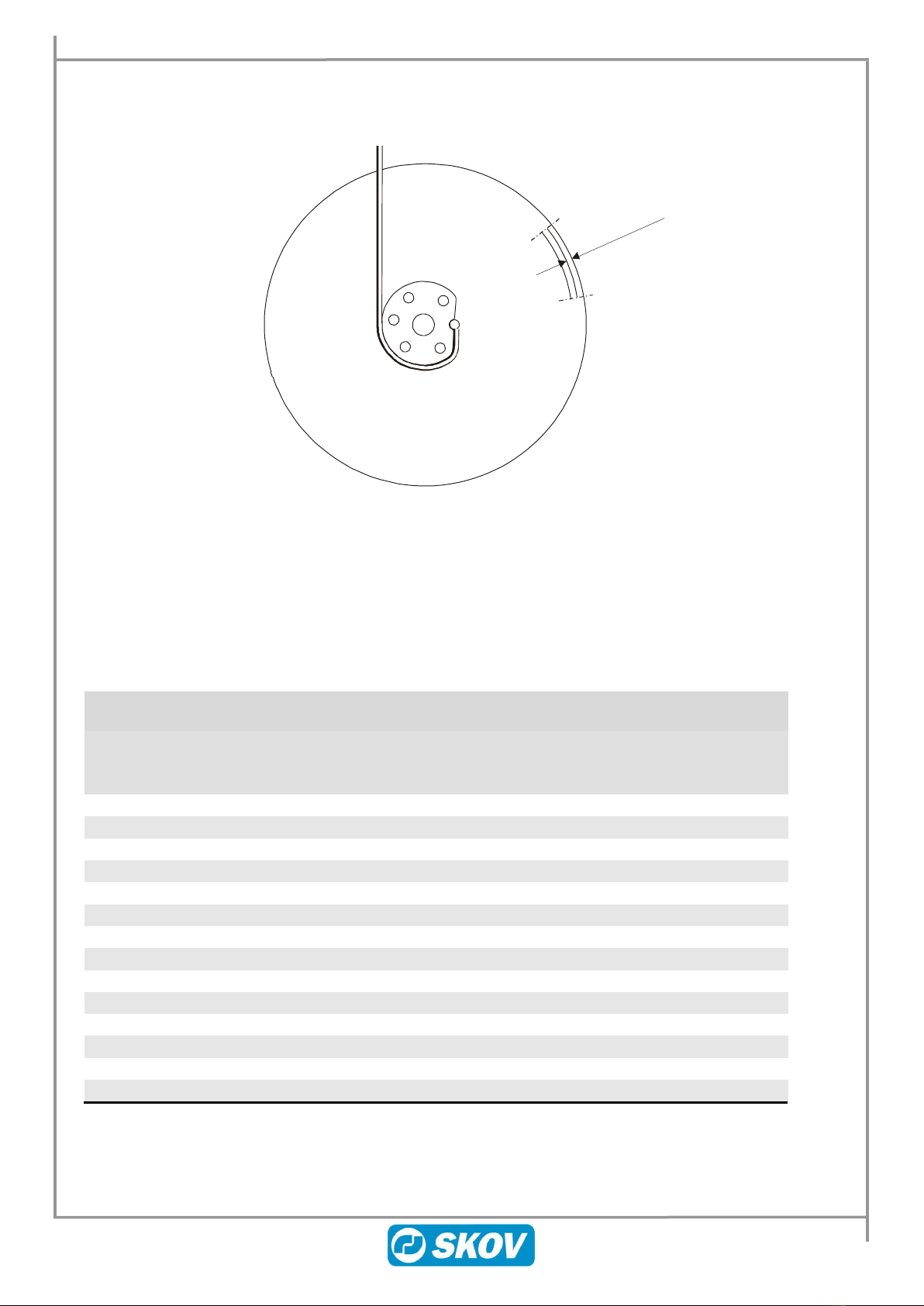
cover and measure the voltage between open (E) and neutral (N) on terminal J1 (Figure 5). If the voltage is
O.K. and the motor does not run, replace the gear motor or the motor capacitor (H). If the voltage is not O.K.,
replace the circuit board. If the opening limit switch (O on Figure 5) is activated, set switch (C) to close
position (downwards) and measure the voltage between close (G) and neutral (N) on terminal J1. If the external
motor temperature exceeds 110°C, a thermal cut-out (T) is activated and the motor cannot run.
Figure 5
5.1 Replacement of the circuit board
Mark the wires connected to opening, closing and to the potentiometer. Remove the plug, unscrew and remove
the wires of J1 and J4. Loosen the 3 bolts by means of the enclosed Allen key and pull out the circuit board.
Adjust the potentiometer shaft (P) on the new circuit board to fit into the hole of the large gear-wheel. Remount
the circuit board. If the motor is in a position where it is being activated by the limit switch, it is necessary to
help the arms of the limit switch contacts (O) and (S) on to the cam of the gear-wheel. The thermal cut-out (T)