SKP Pro Audio MAX TRIO-1310 User manual

1
MAX TRIO SERIES
PROFESSIONAL
POWER
AMPLIFIER
MAX TRIO-1310/2010
OWNER’S MANUAL

2
Safety Information
CAUTION: To reduce the risk of electric shock, do not remove any cover(or the rear section). No user serviceable parts
inside. Refer servicing to qualified service personnel only.
WARNING: To reduce of fire or electric shock, do not expose this appliance to rain and moisture. Electrical equipments
should NEVER be kept or stored in damp environments.
This symbol, wherever appears, is intended to alert the user to the presence of un-insulated
dangerous voltage within the appliance’s enclosure that may be of sufficient magnitude to a risk of
electric shock.
This symbol, wherever appears, is intended to alert the user to the presence of important operating
and maintenance (servicing) instruction in the literature accompanying this appliance.
This symbol means: indoor use only.
This symbol means: Read instructions.
Safety Instructions
1. Read Instructions All the safety and operating instructions should be read before this products is connected
and used.
2. Retain Instructions The safety and operating instructions should be kept for future reference.
3. Heed Waning All warnings on this appliance and in these operating instructions should be followed.
4. Follow Instruction All operating and other instructions should be followed.
5. Heat, Water and Moisture Do not place this appliance to close to any high heat sources such as radiators. Also
this appliance should be kept away from direct contact with liquids.
6. Ventilation The appliance should be situated so that it’s location or position does not interfere with it’s proper
ventilation. For example, the appliance should not be situated on a sofa, bed, or similar surface that may block the

3
ventilation opening; or keep the appliance away of those objects such as newspapers, carpet which may cover the
ventilation opening or impede the flow of air through the ventilation opening.
7. Power Source & Power Cord This appliance should be connected to a power supply only of the type described
in these operating instructions, or marked on the unit.
Power supply cord should be routed so that the are not likely to be walked upon or pinched by the items placed on or
against them. When removing the cord from a power outlet be sure to remove it by holding the plug attachment and
not by pulling on the cord.
Check the total maximum power of your AC wall outlet and make sure it has the enough power to match the Power
Consumption of this appliance, otherwise you could overload the wall outlet, which could cause fire.
8. Internal / External Voltage Selectors Internal of external voltage selector switches, if any, should only be reset
and re-equipped with a proper plug for alternative voltage by a qualified service technician . Do not attempt to alter
this yourself.
9. Object & Liquid Entry Take care to avoid any objects falling into or liquids are not spilled in to the inside of the
appliance.
10. Cleaning Unplug the appliance first and clean only with a dry cloth.
11. Non-use Period The power cord of the appliance should be unplugged from the outlet when left unused for long
periods of time.
12. Unpacking & Setup Please check your appliance for any damage after unpacking(before connecting) and
contact your dealer in case of any related complains. Take care of choosing your installation place and the correct AC
connection. If built in to a case, be aware that the depth and the weight of some kind appliance(such as Amplifier)
does require an additional fixing on the backside or the use of rack shelf supports. Never mount the amplifier in a rack
just by fixing it on the front plate – Manufacturer takes no responsibility in this case.
13. Damage Requiring Service Servicing is required when the appliance has been damaged in any way, such as
power cord or plug is damaged, liquid has been spilled or objects have fallen in the appliance, the appliance has been
exposed to rain or moisture, does not operate normally, or has been dropped. Refer all servicing to qualified service
personnel or contact your dealer. Do not attempt to repair by yourself.
Front panel:
1: Main switch
Used to turn the amplifier on and off. A few seconds after switching
on the amplifier it is ready for operation.
2: CH1/CH2 Gain controls
These potentiometers are used to control the input sensitivity of the amplifier for the satellites. Each channel has its own
control.
You can use these controls to set the maximum sound level of your setup:
●Turn both controls on the amplifier (1) to the left.
●Put on some music on and make sure the VU meters on your mixer are at 0dB. (from time to time the red zone is lit)
●Set the Master output from your mixer to maximum.
●Open the Gain controls from the amplifier (1) until the ma$imum desired sound level is reached.
4
●Make sure nobody can reach the Gain controls of the amplifier. You have just set the ma$imum level the DJ is able to
produce. Your neighbors will be glad….. (in some cases the DJ is not )
3. SUB bass gain control:This potentiometer is used to control the sensitivity of the sub bass amplifier. Put on some
music and turn this control slowly up until there?s a nice balance between the high/mid satellite speakers and the
subwoofer.
4: Protect LED:
The protection LED is on when the speakers are disconnected from the amplifier. This occurs in the following situations:
5: Clip LED
Turns on just before the maximum, distortion free, output level of the amplifier. The clip leds may turn on shortly from time
to time but they may certainly not turn on for longer periods. In this case you have to turn the output level down!
6: SUB phase invert indication LED
Truns on when the phase invert switch( rear panel) was pressed, indicate current SUB output phase was 180°inverted.
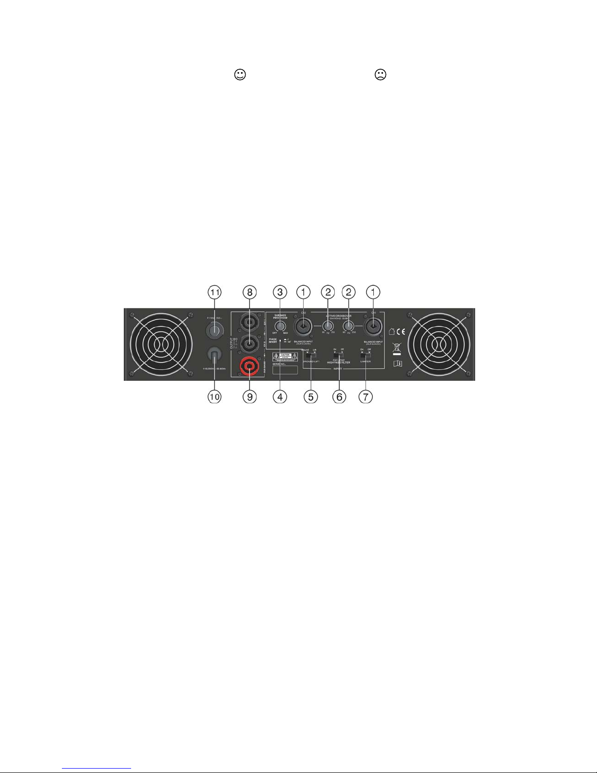
REAR PANEL:
1: CH1/CH2 XLR/JACK inputs
You can connect these balanced inputs to balanced and unbalanced line level audio sources (example: DJ-mixer)
2: X-OVER FREQ. control
(crossover frequency control) adjusts the cutoff frequency of the active filter. This crossover frequency can be set in a
range of 90 to 250Hz. It up to you to adapt its position to your own taste. For most subwoofers 90Hz to 150Hz seems to
be the best choice.
3: SUB processor
Controls the amount of low band signal, produced by the bass processor, from zero to maximum. The setting depends on
the application and can be adapted to your own taste.
Important : Note that the bass processor should be used with care to avoid possible speaker damage. Most smaller and
economical subwoofers are not capable of handling the low frequencies produced by this unit.
4: PHASE INVERT switch
Sometimes the conductors of the subwoofer are inversed which results in poor sound quality with a lack of low
frequencies: the opposite of what you expected! This can be corrected by inversing the (+) and (-) poles of the cabling to
your subwoofer or …… by pushing the PHASE INVERT switch! Use a thin pen to press the phase invert switch and
compare the results of both positions. The position with the most bass production is the right one!
5: GROUND LIFT switch
In some cases nasty hum noises can occur due to ground loops in your setup. Setting the Ground lift switch to the position
“lift”breaks the ground loop between the amplifier and the chassis grounds of various other components in your setup. As
a result the hum noises disappear.
5
6: HIGH PASS FILTER
With this switch you can choose to filter the satellite outputs or not. If you use small satellite speakers than we strongly
suggest to switch the high pass filter on to protect the small speakers. If you use bigger satellite speakers (for example
15” than you can switch this filter off. The satellite speakers will receive more low frequencies.
7: LIMITER switch
This amplifier has build-in limiters to protect both the amplifier and the connected speakers. We strongly suggest to put
this switch in on position at all times. Nevertheless if you are experienced or you use an external limiter you can switch the
internal limiters off.
8: CH1/CH2 outputs Speakon
use these Speakon compatible connectors to connect your mid/high satellite cabinets. Refer to chapter “connections”to
learn which cables are suitable.
(Speakon wire connector. 1+ 2+, 1- 2-)
9: SUBWOOFER output:use this Speakon compatible connector to connect your subwoofer cabinet. Refer to chapter
“connections” to learn which cables are suitable.
(Speakon wire connector. 1+ 2+, 1- 2-)
10: Mains input
When all audio cables are connected, you can connect this cable to mains outlet.
11: RESET button
this amplifier uses an automatic fuse. When the fuse is blown, simply press the button to rearm it.
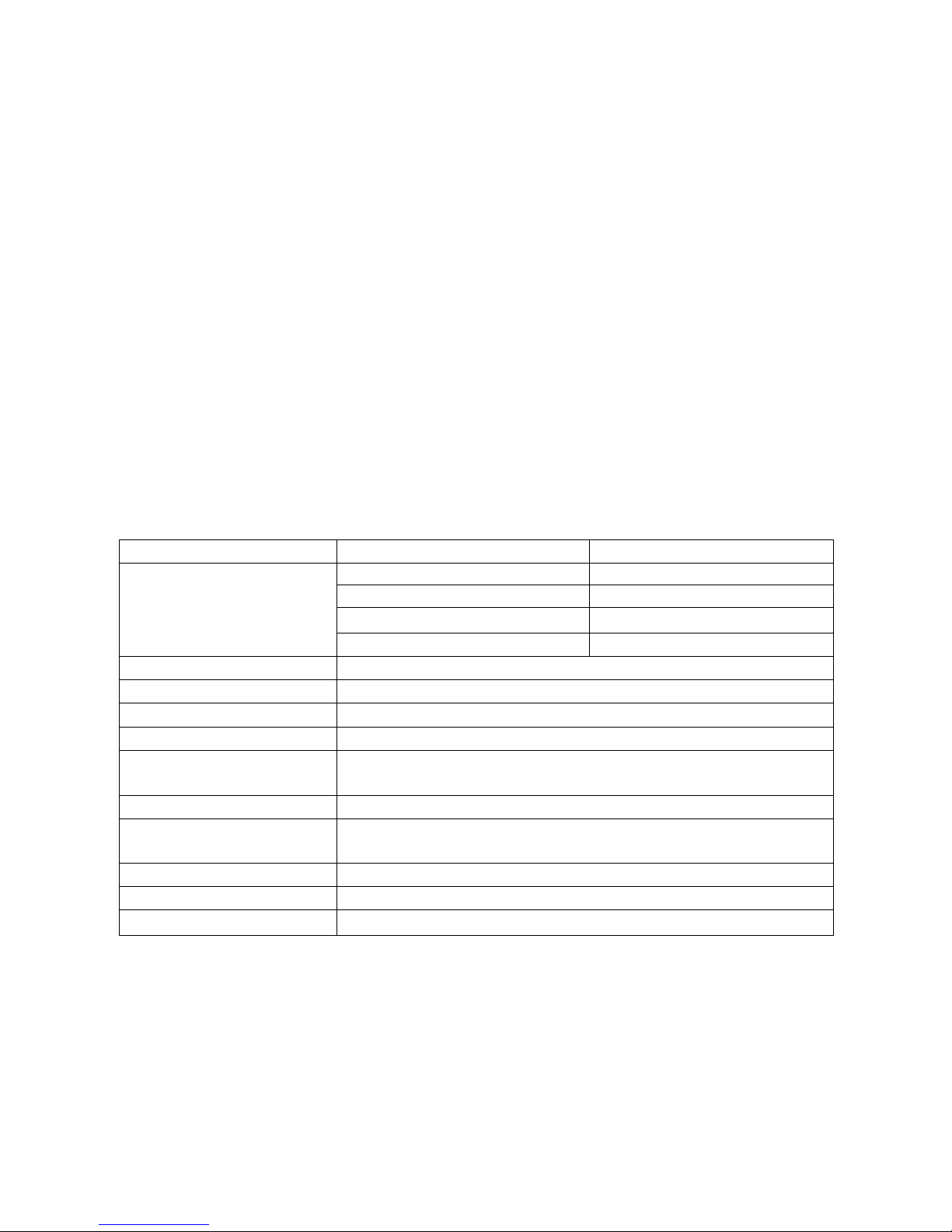
TECHNICAL PARAMETER OF TRIO SERIES AMPLIFIER:
Model MAX TRIO-1310 MAX TRIO-2010
OUTPUT STEREO 8
Ω
POWER STEREO 4
Ω
SUB 8
Ω
SUB 4
Ω
200W+200W 300W+300W
350W+350W 500W+500W
400W 600W
600W 1000W
FREQUENCY RESPONSE 20Hz--20KHz (0dB, -1.5dB)
INPUT SENSITIVITY 770mv
INPUT IMPEDANCE 20K
Ω
(BALANCE) 10K
Ω
(UNBALANCE)
S/N RATIO >90dB
CROSSTAL
@
RATEDOUTPUT
8Ω/1KHz
>65dB
DAMPING FACTOR/8
Ω
/1KHz >300
PROTECTION SOFT START. SHORT CIRCUIT.CURRENT LIMITED, DC FAULT, AC LINE FUSE,
THERMAL CUT
INDICATOR POWER,PROTECT,CLIP,SIGNAL,SUB phase revert
COOLING SYSTEM
2 x dual Speed Fans
MAINS POWER SUPPLY
AC 115V/230V 50/60Hz
Table of contents
Other SKP Pro Audio Amplifier manuals


Popular Amplifier manuals by other brands

Rotel
Rotel RA-1312 owner's manual

Luxman
Luxman SQ700X Operation manual

WiMo
WiMo challenger II GS 35 Operating manual and parts list

Galls
Galls Street Thunder ST280 Installation and operating instructions

Ground Zero
Ground Zero TITANIUM Series owner's manual

Lab.gruppen
Lab.gruppen FP+ Series FP 10000Q Operation manual

Link electronics
Link electronics Analog Pulse Distribution Amplifier DigiFlex... Specification sheet

Quanser
Quanser VoltPAQ-X2 quick start guide

US Blaster
US Blaster USB 7137 owner's manual

Janus
Janus AudioControl Director M4800 user guide

Steren
Steren AMP-017 instruction manual

DYNACO
DYNACO Stereo 120 manual


