Galls Street Thunder ST280 User manual

PLITSTR311 REV. G 7/25/14
ST280
SIREN AMPLIFIER & LIGHT CONTROLLER
INSTALLATION AND OPERATING INSTRUCTIONS
1340 Russell Cave Road / P.O. Box 5430 Lexington, KY 40505
Tel: ( 00) 477-7766 Fax: ( 00) 944-2557
www.galls.com
Street Thunder™
Street Thunder™Street Thunder™
Street Thunder™

-i-
TABLE OF CONTENTS
GENERAL DESCRIPTION 1
INSTALLATION NOTES 1
INSTALLER SELECTABLE OPTIONS 2-3
MOUNTING 4
ELECTRICAL CONNECTIONS 4-9
Wire Size and Termination 4
Mandatory Siren Electrical Connections 5
Optional Siren Electrical Connections 6
Siren Wiring Diagram 7
Lighting Electrical Connections
Button Label Insertion
Lighting Wiring Diagram 9
OPERATION 10-13
ON/OFF Switch 10
Lighting Slide Switch 10
Lighting Push Button Switches 11
Selector Switch (Rotary Knob) 11
Manual/Horn Rocker Switch 12
Volume Controls 13
Microphone 13
Auxiliary Input 13
Park Kill 13
Speaker Diagnostics 13
SERVICE 14-15
FUSES 14
TROUBLESHOOTING 15
SPECIFICATIONS 16
LIMITED WARRANTY 17
RETURNS 17
NOTICE
Due to continuous product improvements, we must reserve the right to change any specifications
and information contained in this manual at any time without notice. Galls and/or the
manufacturer make no warranty of any kind with regard to this manual, including, but not limited
to, the implied warranties of merchantability and fitness for a particular purpose. Galls and/or the
manufacturer shall not be liable for errors contained herein or for incidental or consequential
damages in connection with the furnishing, performance, or use of this manual.
INSTALLATION INFORMATION
MODEL:
ST280
SERIAL #:
PURCHASE DATE: INSTALLER:
DEALER: INSTALLATION DATE:
OPTION JUMPERS
Negative Auxiliary Switching Audible Beep disable
Negative Park Kill Switching 8 sec. gun lock S4
wo- one Enabled Auxiliary Override
hunder Disabled Pursuit Disable
Model and serial number located on bottom of unit

-1-
The ST2 0 Siren Amplifier is a premium 200W unit designed for single or dual 100W
speaker use and full lighting control.
The primary operating modes are Thunder, Yelp, Wail, Hands Free, Manual, PA, and
Radio. A Noise Canceling PA Override and push-button Horn Override are available
in all modes. A rocker switch is provided for momentary tone toggle operation in
the Thunder, Yelp, and Wail modes. It also allows manual siren control in the Manual
or PA modes. The Thunder function can be optionally replaced by Two-Tone or
disabled entirely with program jumpers. Another feature allows cycling through
Wail, Yelp, Thunder, and Standby by providing a signal to the horn ring auxiliary wire
when the function switch is in the Hands Free (HF) position. A Park Kill option is
provided for connection to a door switch, etc. to disable the siren when exiting the
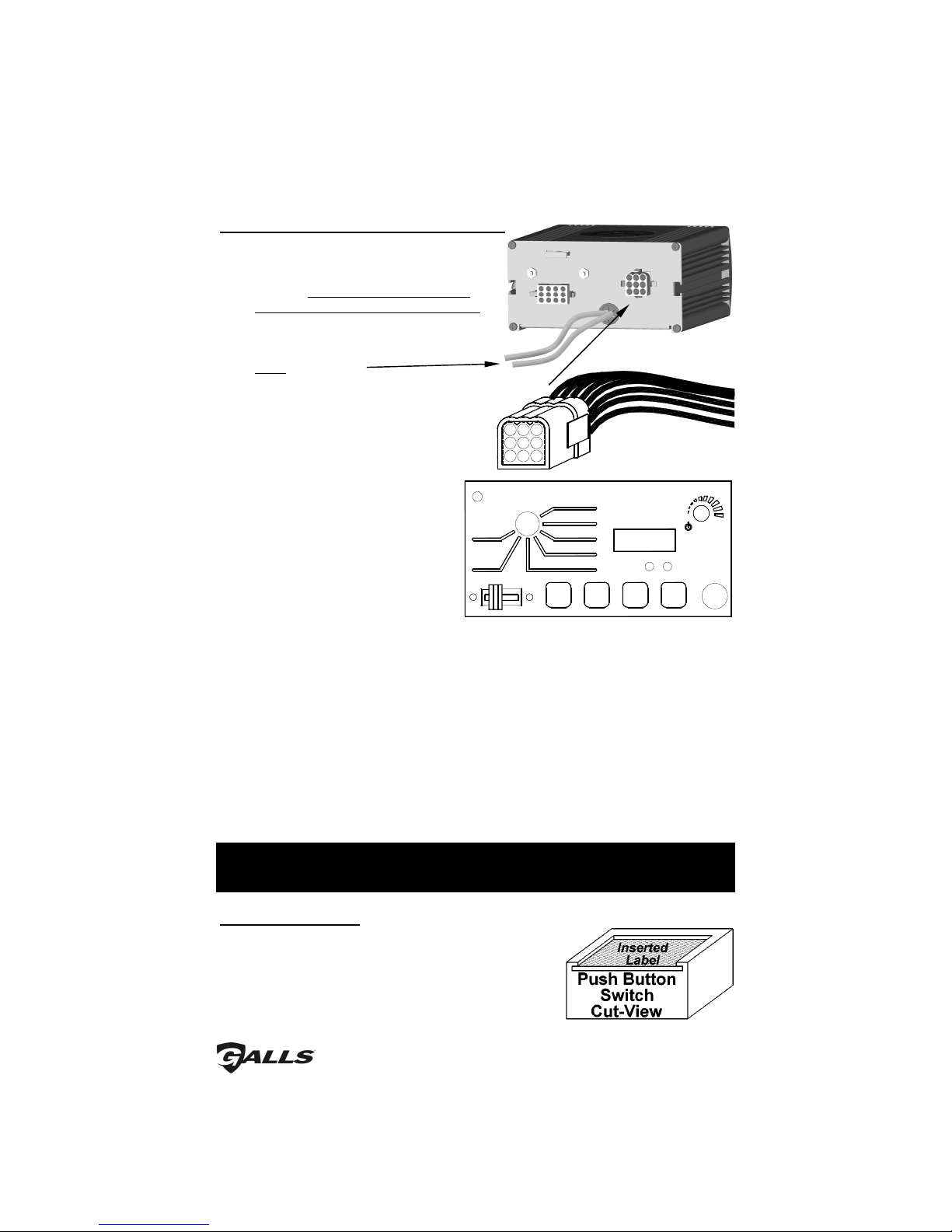
vehicle. Radio and PA volume controls are provided on the front panel. Also
located on the front panel are two LED's for speaker diagnostics.
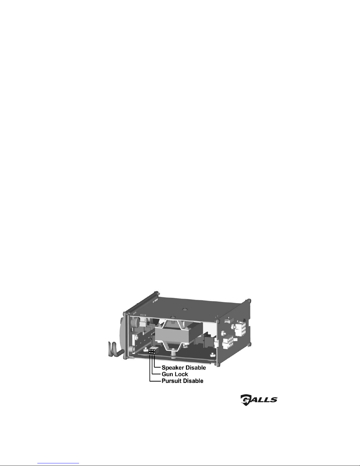
This unit additionally contains several distinct controls for operation of vehicle
devices. A slide switch allows quick pursuit mode operation. The far right slide
position can be set up to activate maximum lights and siren for pursuit mode. There
are four push buttons to control four different lighting or auxiliary functions.
The front panel is backlighted with LED's for night visibility. This compact unit utilizes
short circuit, high voltage, low voltage, and reverse polarity protection systems for
maximum service life.
General Description
Installation Notes
Proper installation of the unit is essential for years of safe, reliable operation. Please
read all instructions efore installing the unit. Failure to follow these instructions can
cause serious damage to the unit or vehicle and may void warranties.
Qualifications - The installer must have a firm knowledge of basic electricity, vehicle
electrical systems, and emergency equipment.
Keep These Instructions - Keep these instructions in the vehicle or other safe place
for future reference. Advise the vehicle operator of the
location.
Unpacking - Immediately inspect the contents for shipping damage. If any
damage is found, alert the carrier immediately.
Contents should include:
1 - unit with microphone
1 - wire harness with connector
1 - microphone bracket w/2 screws
1 - mounting hardware
1 - “U” bracket
1 - label set
1 - installation and operating instructions
Please contact your supplier immediately if any components are missing.

-2-
Installer Selectable Options (Jumper Settings)
The ST2 0 has several options that can be selected during installation. Jumpers on
the printed circuit board, inside the case, allow the installer to select these various
options. These options should be set before installation of the unit.
• Park Kill input polarity
• Auxiliary input polarity
• Two-tone replacement of Thunder tone
• Thunder Disable
• Slide Switch Pursuit Siren Disable
• Speaker (Audible Beep) Disable
• second timed gun lock release (S4)
Cover Removal - Remove the
four Philip head screws
located on the ack of the
unit. DO NOT REMOVE THE
SCREWS ON THE FRONT OF THE
UNIT! Slide the top cover off
the front face of the unit.
Take care not to damage the
microphone cord during this
procedure. This cover can be
removed completely from the
siren unit. Carefully slide the
cover over the microphone
and set it aside.
Park Kill Input Polarity -
The park kill (cutout)
input turns off any siren
tone output when
activated (i.e. vehicle
shifted into park, door
opened, etc.), and
remains off until a control
on the siren is activated
or changed. The wiring
diagram on page 7
shows two connection
examples.
The park kill input is normally activated by connecting the gray wire to positive
voltage. To activate by connecting it to ground (negative) instead, move the
jumper from the "PK-POS" pins to the "PK-NEG" pins.
After the cover has been removed, find the location of the option jumpers (see the
diagram below).

-3-
Auxiliary Input Polarity - The auxiliary input (green wire) is normally activated by
applying a positive voltage to the wire. To activate by connecting to ground
(negative), move the jumper from the "AUX-POS" pins to the "AUX-NEG" pins.
Auxiliary Input Function - The auxiliary input (green wire) allows activation by an
external source of either the Horn or the Manual push-button functions. This input is
usually wired into the vehicle horn switch. The wiring diagram on page 7 shows two
connection examples. NOTE: Permanent disconnection of the vehicle horn is NOT
recommended.
The siren is factory shipped with the auxiliary input option defaulted as the Horn
function (on only one of the "AUX" pins). To utilize the auxiliary input as the Manual
function instead of the Horn function, move the "AUX" jumper from one pin onto
both of the pins.
Two-Tone – The Thunder sound can be replaced by a Two-Tone sound by moving
the "TT" jumper from one pin onto both of the "TT" pins.
Thunder Disa le - The Thunder function can be completely disabled by moving the
"TD" jumper from one pin to both pins. This will also disable the Two-Tone function
used when the manual button is pressed while the mode switch is in the Thunder
position.
Pursuit Disa le - The farthest right slide switch position (L3) will normally activate the
siren output in the wail mode, along with all three light functions. Automatic
activation of the siren. If you prefer to NOT have the siren automatically activated
when the slide switch is moved to position three, move Pursuit Disable jumper onto
only one pin.
8 second timed gun lock release (S4) - The amplifier is shipped with the fourth push
button (S4) as a standard on/off button. It can be optionally selected to stay
activated for only seconds when pressed. To change button (S4) to a timed
unlock remove the Gun Lock jumper and place it only on one pin.
Speaker Disa le (Audi le eep disa le) - The audible beep heard when the light
control buttons on the siren are pressed can be disabled. If you move the Speaker
Disable jumper from both pins onto only one pin, the audible beep will cease.
(Installer Selectable Options ONT’D)

-4-
Mounting
SAFETY PRECAUTIONS
For the safety of the installer, vehicle operator, passengers and the community
please observe the following safety precautions. Failure to follow all safety
precautions and instructions may result in property damage, injury or death.
• Mount in a location with adequate ventilation to prevent overheating.
• Devices should be mounted only in locations listed in SAE standard J1 49.
• Controls should be placed within convenient reach of the driver.
• Assure clearances before drilling in vehicle.
• Sound levels produced by attached speakers can cause permanent hearing loss.
• Never operate this unit without adequate hearing protection for you and others
in the area. (OSHA 1910.95)
• Consider wire routing and access to connections.
• Install mounting bracket to vehicle using 1/4" hardware (not supplied).
• Drill 1/ ” holes and install the microphone bracket to the vehicle using the
two included screws.
Electrical onnections
Wire Size and Termination
Electrical connections to this unit are made through the green 12-terminal
connector located in the rear of the unit (See below - Part # CPSS-153).
Examine the charts on the following page to determine the proper gauge of the
wire to use. Please review the following recommendations when making your
electrical connections:
• For safety and reliability we highly recommend that you always use both Power
wires (pins 1 & 4) and both Ground wires (2 & 5).
• Use only high quality crimp connectors. Make sure all connections are tight.
• Minimize the number of splices to reduce voltage drop.
• Route wiring to prevent wear, overheating, and interference with air bag
deployment.
• Use grommets and sealant when passing through compartment walls.
• Ground connections should be made directly to the negative of the vehicle
battery. Where not possible, only connect to substantial chassis components.
• Install and check all wiring before connection to vehicle battery.
• CAUTION: All wires should e rated for at least 125% of their maximum current
load. All wires connected to the positive terminal of the attery should e fused
at the attery for their rated load.
• Review the charts on the following page that indicate the recommended wire
gauge, based upon the length of the wire run and the current that will pass
through the wire.

-5-
Mandatory Electrical Connections For Siren Functions
BLAC : (Pins 2 5) Ground - Connect these leads to the negative of the
battery, or to a good chassis ground. You MUST connect both
leads if you are using two 100-watt speakers. Be sure to use minimum
size #14 AWG wire.
RED: (Pins 1 4) Power - Connect both leads to the positive side of the battery, or
to a high current power buss. You MUST connect both leads if you are
using two 100-watt speakers. A power relay may also be used. Be sure to
use minimum size #14 AWG wire.
YELLOW: (Pin 11) Ignition Switched Power - Connect to +12VDC through a
switched power supply (possibly ignition). This will turn the siren on and
off. Be sure to use minimum size #1 AWG wire.
Note: The siren WILL NOT function unless +12VDC is present on this wire.
ORANGE: (Pin 9) Backlight Power - This lead supplies power for the backlighting of
the siren. Connect it to +12VDC from the dash lights, parking lights or
other switched source. Be sure to use minimum size #1 AWG wire.
BROWN: (Pins 7 12) Speaker Output - Connect one lead to each terminal or
lead of the speaker. Be sure to use minimum size #14 AWG wire. If
connecting a second speaker in parallel, you must o serve the polarity
of the speakers (phasing). Be sure that the positive terminals of oth
speakers are connected together to the same rown wire from the
siren. In which case, the negative terminals of both speakers would
also be connected together to the other brown wire.
Terminal
Description Color Typical
Current
1 Power Red 10A
2 Ground Black 10A
3 Radio Repeat Blue 0.1A
4 Power Red 10A
5 Ground Black 10A
6 Radio Repeat Blue 0.1A
7 Speaker Brown 4A
Park Kill Gray 0.1A
9 Backlighting Orange 0.1A
10 AUX Out Green 3A
11
Ignition
Switched
Power Yellow 0.1A
12 Speaker Brown 4A
WIRING GUIDE
Current
10'
20'
25'
< 2.0A 22 AWG 1 AWG 1 AWG
2.0-4.0A 1 AWG 16 AWG 16 AWG
4.1-5.5A 1 AWG 16 AWG 14 AWG
5.6- .0A 16 AWG 14 AWG 14 AWG
.1-12.0A 16 AWG 12 AWG 12 AWG
RE OMMENDED WIRE GAUGE
(Electrical onnections ONT’D)
11
9
1 2
6 5
7
1 0
4
2
31
Siren input and output
connections are made on
the back of the unit through
a 12-pin connector and
wiring harness.

-6-
(Electrical onnections ONT’D)
Optional Connections for Siren Functions:
BLUE: (Pins 3 6) Input From Radio - Used for radio repeat. Connect one
blue lead to each terminal of the radio speaker or output
connector of the radio. Most radio outputs are isolated, in which
case polarity would not be important. Radios with polarity sensitive
outputs should be connected w/ the blue wire from pin 6 to the
positive radio output, and the blue wire from pin 3 to the negative
radio output. Use #1 AWG wire.
GREEN: (Pin 10) AUX or Horn Ring - Used for remote Manual (or Air Horn)
control. Connect to the horn ring circuit or some other remote
switch. Circuit may be positive or negative with proper jumper
selection. See INSTALLER-SELECTABLE OPTION section (page 3 and
4) for jumper details.
NOTE: Cut lead short if not used & insulate w/ electrical tape.
GRAY: (Pin 8) Park Kill (Cut-off) – This wire is used to de-activate the siren
when the vehicle is exited. Connect to dome light or added door
switch. Circuit may be positive or negative with proper jumper
selection. See INSTALLER-SELECTABLE OPTION section (page 2) for
jumper details.
NOTE: Be sure to cut lead short if not used and insulate with
electrical tape.
Testing - Test all siren functions after installation to assure proper
operation. Test vehicle operation to assure no damage to vehicle.

-7-
(Electrical onnections ONT’D)
Positive
Switching AUX
Horn Jumper
Selected
Negative
Switching AUX
Horn Jumper
Selected
Backlighting Switch (Connect to
Dash Lights, Parking Lights, Etc.)
Siren Wiring Diagram
+12 VDC +12 VDC
Horn
Switch/Relay
VEHICLE
HORN
Horn
Switch/Relay
OR
ON/OFF Power Switch for Siren
(Possibly Connected to Ignition)
+12 VDC
VEHICLE
HORN
+12 VDC
+12 VDC
+
SIREN
AMPLIFIER
9 - Orange (#18 AWG)
11 - Yellow (#18 AWG)
12 - Brown (#14 AWG)
10 - Green (#18 AWG)
8 - Gray (#18 AWG)
6 - Blue (#18 AWG)
7 - Brown (#14 AWG)
2 - Black (#14 AWG)
4 - Red (#14 AWG)
5 - Black (#14 AWG)
3 - Blue (#18 AWG)
1 - Red (#14 AWG)
+
SPEAKER 2
11 OHMS
SPEAKER 1
11 OHMS
Negative Switching PK
Jumper Selected
Positive Switching PK
Jumper Selected
OR
Dome
Light
Door Switch
+
RADIO
+
Connect the Blue wires to
the terminals of speaker or
to the output jack of radio
BA ERY
Added Door
Switch

-8-
(Electrical onnections ONT’D)
Radio
PA
Thunder
Yelp
Wail
HF
Manual
Radio
Speakers 1 2
Manual Horn
S1 S2 S3 S4
L1 L2 L3
PA
5
2
9
3
6
7
1
4
Electrical Connections For Lighting Control
RED: (8 AWG) +12VDC Power -
The two large red wires exiting the back
of the siren should be connected to
+12VDC through a fuse rated for the
TOTAL current draw of ALL of the lights
controlled by this unit. They will supply
the power to the lights hooked up to the
9-pin connector. You must connect
BOTH red wires.
9-Pin Connector
(REFER TO THE LIGHT WIRE DIAGRAM ON
THE NEXT PAGE FOR PROPER WIRE SIZES!)
The electrical connections for slide switch
outputs, and for the push button light
functions outputs are located on the
square 9-pin connector (part #SWH-49)
on the back of the siren.
Empty (Pin 1)
Empty: (Pin 2)
Orange: (Pin 3) L1 Output – This power output is activated when the slide switch
is in the 1
st
, 2
nd
, or 3
rd
position.
Yellow: (Pin 4) S4 Output - Output power to lights controlled by S4 button.
Green: (Pin 5) S2 Output - Output power to lights controlled by S2 button.
Blue: (Pin 6) S3 Output - Output power to lights controlled by S3 button.
Violet: (Pin 7) S1 Output - Output power to lights controlled by S1 button.
Gray: (Pin 8) L2 Output – This power output is activated when the slide switch is
in the 2
nd
or 3
rd
position.
White: (Pin 9) L3 Output – This power output is activated when the slide switch is
in the 3
rd
position.
Testing - Test all siren and light functions after installation to assure proper
operation. Test vehicle operation to assure no damage to vehicle.
ButtonLa el Insertion
Once the wire connections have been made to S1
through S4, labels can be inserted into the switches.
The product is shipped with 30 different labels for these
push buttons. Select the desired label inserts
(provided). Insert the label into each button and tuck
it under the lip of the switch.

-9-
(Electrical onnections ONT’D)
AMPLIFIER
+
BA ERY
20A
20A
20A
20A
20A
20A
Red (#8 AWG)
Red (#8 AWG)
Lights to be activated when
Slide Switch is in Position 3
PIN 8 - GRAY (#12-16 AWG) - L2
PIN 4 - YELLOW (#12-16 AWG) - S4
PIN 3 - ORANGE (#12-16 AWG) - L1
PIN 9 - WHI E (#12-16 AWG) - L3
PIN 7 - VIOLE (#12-16 AWG) - S1
PIN 1 - EMP Y
PIN 2 - EMP Y
PIN 5 - GREEN (#12-16 AWG) - S2
20A PIN 6 - BLUE (#12-16 AWG) - S3
Lights to be activated by
Pushbutton Switch S1
Lights to be activated by
Pushbutton Switch S2
Lights to be activated by
Pushbutton Switch S3
Lights to be activated by
Pushbutton Switch S4
Lights to be activated when
Slide Switch is in Positions 2 & 3
Lights to be activated when
Slide Switch is in Positions 1, 2, & 3
Slide Switch Lights Pushbutton Lights
FUSE
Fuse the input wires at the
battery for the O AL amp
draw of all the lights combined

-10-
Operation
General
This unit is designed for easy operation under the stress associated with high-speed
pursuit. Most siren functions are accessible with one simple motion without
repetitive activation of switches or automatic timed switching that can interfere
with desired operation.
On/Off
The On/Off-PA volume control (PA) will both turn the ST2 0 unit
on and off, as well as control the public address volume. It is
located in the upper right hand corner of the front face.
When the unit is not in use, you may elect to leave this switch
in the OFF position. To turn the unit Off, rotate the switch
counter clockwise until it clicks. This will power down the unit
and will prevent accidental activation of any of the controls
on the face of the unit. Rotating the knob clockwise will
power up the ST2 0. THIS SWITCH MUST BE TURNED ON FOR
ANY OF THE FUNCTIONS TO WOR .
Lighting Slide Switch
The slide switch is designed for quick pursuit mode
operation. The far left position (OFF) will not activate
any outputs. Position 1 will activate the first set of
lights (connected to L1). Position 2 activates both
the first and second set of lights (connected to L1
and L2). Position 3 activates all three sets of lights
(connected to L1, L2 and L3), along with the siren.
Each output is protected with a 20A fuse.
Pursuit Mode - Position 3 (farthest right) is generally used for the full pursuit mode. It
allows for a quick procedure that will activate both the lights and the
siren in one motion. When the slide switch is moved to Position 3, all
three sets of lights will turn on and the siren will activate into the Wail
mode.
The siren may be disabled in the pursuit mode during installation if
desired. (Refer to the section on page 3 under INSTALLER SELECTABLE
OPTIONS).

-11-
(Operation ONT’D)
Selector Switch
Whenever +12VDC is applied to the
yellow wire, the siren will be "on" in
the selected mode. The rotary
selector switch controls the primary
operating function of the siren.
Lighting Push Button Switches
Four push button switches are provided to enable four separate functions. They
activate the corresponding outputs S1, S2, S3, and S4. (See pages 8-9)
S1 S2 S3 S4
Thunder - Ultra-fast changing tone used for maximum attention.
Yelp - A rapidly changing tone used in congested areas.
Wail - A slower changing tone used on highways.
HF (Hands Free) - Also known as Horn Ring Cycler, allows the user to cycle through
Wail, Yelp, Thunder and Manual by repeatedly pressing the horn
or other switch connected to the AUX input. Operating any other
switch resumes normal operation. Please note that this mode
disables the Manual push-button selection when a Wail, Yelp, or
Thunder tone is cycled to.
Manual - A silent mode that allows push-button Manual, push-button Horn,
and Public Address operation. The siren output winds down when
the Manual momentary rocker switch is released.
PA - A silent mode that allows push-button Manual, push-button Horn
and Public Address operation. The siren output terminates
immediately when the Manual momentary rocker switch is
released.
Radio - Also known as Radio Repeat, this function amplifies a radio
speaker input for re-broadcast outside the vehicle. The PA
remains functional, but no siren tones are available in this position.

-12-
(Operation ONT’D)
Manual/Horn Momentary Rocker Switch
The front panel of the ST2 0 contains a momentary rocker switch that operates the
Manual function when the left side is depressed and the Air Horn when the right
side is depressed.
Optional operation includes replacement of the Thunder tone with Two-
Tone or disabling the Thunder tone entirely. These options are selected
during installation and may be governed by State or Local laws.
Manual – Pressing the left side of this momentary rocker
switch provides a generally quicker changing
tone when the selector switch is in the Wail, Yelp
or Thunder positions. (See table on page 12).
These quicker tones are used at intersections
and very highly congested areas. Pressing the
button once changes to the next faster tone
and pressing again changes the tone back to
original tone. With the selector switch in the
Manual, PA or Hands Free position this switch
provides a manually activated Wail siren tone
while the button is being held. This is used to
momentarily alert motorists or in low noise areas.
(NOTE: THUNDER and TWO-TONE may be optionally swapped or disabled via
program jumpers. See the section on page 4 under INSTALLER-SELECTABLE
OPTIONS.)
Air Horn – Pressing the right side of this momentary rocker switch provides a
simulated air-horn tone while pressed. This can be used to either replace,
or to supplement the normal vehicle horn and is useful at intersections or
in high noise areas. This tone will override all other siren tones.
Rotary Switch
Position:
Pressing the MANUAL Rocker Switch
Does This:
HUNDER oggles the Output to WO- ONE
YELP oggles the Output to HUNDER
WAIL oggles the Output to YELP
HF (Hands Free) Creates a manual WAIL tone while button is being held that
sweeps down when the button is released.
MAN (Manual) Creates a manual WAIL tone while button is being held that
sweeps down when the button is released.
PA Creates a manual WAIL tone while button is being held that
stops immediately when the button is released.

-13-
(Operation ONT’D)
Volume Controls
The radio repeat volume (Radio) control is recessed in the
upper left hand corner of the front face. This should be set
when the vehicle is parked. First set the volume level of the
vehicle's two-way radio to its normal operating volume. Adjust
the siren's rotary selector switch into the RADIO position. Insert
a small, flat blade screwdriver into the RADIO volume
adjustment port. Turn clockwise direction to increase the
sound level.
The On/Off-PA volume control (PA) will both turn the unit on
and off, as well as control the public address volume. It is
located in the upper right hand corner of the front face.
When the unit is not in use, you may elect to leave this switch
in the OFF position. Turn the switch counter clockwise until it
clicks. This will power down the unit and will prevent
accidental activation of any of the controls on the face of the
unit. Rotating it clockwise will power up the ST2 0. As it is
turned clockwise, the outside volume of the PA will increase.
This should be set when the vehicle is parked. Set the PA
volume to the maximum level with no feedback (squeal).
Microphone
The attached noise-canceling microphone is used for public address operation
and overrides any siren tone when its push-to-talk (button on the side) is pressed.
Auxiliary Input
During installation an auxiliary input may be connected to the vehicle horn ring or
other switching device. It provides the same operation as pressing the Horn button
or optionally (via internal jumpers) the Manual rocker switch.
Park Kill (Cut-Out)
During installation, the Park Kill input may be connected to a door switch. It will
automatically turn off any siren tone when the door is opened. The siren tone will
continue to be cut off even when the door is closed. Changing any switch or input
will restore normal function.
Speaker Diagnostics
There are two diagnostic LED’s located BENEATH THE manual/Horn rocker switch..
These LED’s will only turn on while a tone is trying to be generated. Status of the
speakers are indicated as follows:
Steady - Speaker is connected and
operating properly.
Flashing - There is an electrical short in the
speaker or wires to the speaker.
Off - No speaker is connected, or
- The siren is not activated to output
a tone to the speaker, or
- The speaker or wire connection is
loose or is electrically open

-14-
Service
Fuses
There are several fuses in this unit that protect it from shorts, spikes, and other such
electrical problems that may possibly damage the unit.
The HRT is protected internally by a 2 amp self-resetting fuse. This is not user
serviceable, but will automatically reset once the short is removed.
The entire unit is protected by a 20 amp
automotive type fuse, located on the
back of the unit. If your unit completely
stops working, this fuse should be
checked.
Seven additional fuses are
located inside the control
box. These fuses protect
the seven high-current
light outputs. If only one
of your outputs is not
working correctly, it may
be that the corresponding
fuse for that output has
blown.
Cover Removal - Remove the four Philip head screws located on the ack of the
unit. DO NOT REMOVE THE SCREWS ON THE FRONT OF THE UNIT!
Slide the top cover off the front face of the unit. Take care not to
damage the microphone cord during this procedure. This cover
can be removed completely from the siren unit. Carefully slide
the cover over the microphone and set it aside.
After the cover has been removed, find the location of the fuses (see the diagram
below). Each high current light output is protected with a separate 20A
automotive blade fuse. Check each of these fuses to make sure they are all
working properly, and none have blown.

-15-
(Service ONT’D)
Trou leshooting
This unit is designed to provide years of reliable service under even the worst
conditions. Many times there may appear to be a problem with the unit when the
true problem is in the speaker(s) or improper installation. The following chart shows
typical symptoms and possible causes.
Symptom Possi le Cause Check
No power On/Off PA Vol. Not ON
Yellow wire is not powered
Connector loose
Siren 20A fuse blown
Loose connection at power
source
Be sure the On/Off PA Vol. Knob is not in the OFF position
Is yellow wire connected to switched +12VDC?
Check connector
Is power hooked up backwards? Positive ground vehicle?
Is an external fuse or circuit breaker used?
Are the negative leads connected to a good ground?
No siren tone -
PA works
No siren tone -
No sound
High voltage protection
Low voltage protection
Microphone button stuck
Park Kill polarity option set wrong
Park Kill activated
Bad speaker or speaker wiring
The input voltage must be less than 16 volts.
The input must be greater than 10V with the siren turned on.
Does microphone button release properly?
Is the PK jumper option properly configured?
Does the siren work when Park Kill input is disconnected?
Check for a short.
Check the PA Vol. In ON and turned up
Check for an open.
No PA PA volume not set properly Have you tried turning the PA volume control?
Distorted siren
sound
Speaker assembly loose
Intermittent Aux. Input connection
Low or high vehicle voltage
Is the speaker bell or tip loose?
Is the Aux. Input used and wired properly?
Input voltage must be between 10-16 volts while siren is on.
Intermittent
siren tone
High voltage protection
Low voltage protection
Microphone button activation
Circuit breaker in supply
connection
Shorted speaker or speaker wire
Is the vehicle voltage regulator working properly?
Is the connector tight on the back of the unit? Is there a
loose connection on a power lead? The input must be
greater than 10V with the siren turned on.
Is something lying on the microphone?
Is a circuit breaker used with at least a 50A rating?
Does the speaker have water damage, or is a wire
pinched?
Horn function
or
Manual or
Thunder stuck
on
Manual/Horn rocker switch stuck
Aux. Input improperly connected
Aux. Input Polarity Option set
wrong
Does the switch return fully when released?
Is the Aux. Input used and wired properly?
Is the AUX jumper option properly configured?
No Radio
No or Low
Radio
Unit not connected to radio
Radio volume too low
Radio outputs not isolated and/or
polarity hooked up backwards
Is the radio connected properly to the unit?
Can you hear the radio in the vehicle?
Have you tried turning the Radio volume control?
Are the radio wires connected to the correct polarity from
the radio output?
Wrong siren
tone
Two-Tone option jumper installed
Aux. Input set to wrong function
Is the TT jumper option properly configured?
Is the AUX jumper option configured properly?
Thunder not
working
Thunder disabled Is the TD jumper option configured properly?
One light
output not
working
Internal 20A fuse blown Check the output fuses inside the unit.

-16-
Specifications
Input Voltage 10 - 16 VDC (negative ground)
Input Current .0 Amps @ 13.6 VDC (single 100W speaker)
16.0 Amps @ 13.6 VDC (dual 100W speakers)
Standby Current Less than 15 mA
Audio Frequency 200Hz - 10 kHz + 3db
Speaker Output Power 105 WATTS RMS MAX. (15.0 VDC – single 100W speaker)
200 WATTS RMS MAX. (15.0 VDC –dual 100W speakers)
Siren Frequency 675Hz - 1633Hz
High Voltage Protection 16 - 1 VDC will cause siren output to cease, resumes at normal
voltage
Speaker Short Circuit
Protection Current
50 AMPS (battery must be capable of supplying this for unit to auto
shut-down with a speaker short)
Operating Temperature -15° F to +140°F
Siren Controls 7-position rotary switch (Radio, PA, Manual, HF, Wail, Yelp, Thunder)
Momentary Manual/Horn rocker switch
Auxiliary input (jumper programmable) for positive or negative horn
-Remote Manual or Hands Free operation
Park Kill input (jumper programmable) for positive or negative
activation
Thunder (and Two-Tone) disable (jumper programmable)
Two-Tone activation (swaps modes with Thunder) (jumper
programmable)
Diagnostic Indicators Two LED indicators provide diagnostic feedback, one for each
speaker
Light Controls 4 push-on/push-off buttons (1 programmable sec. time delay)
4-position slide switch (Off, L1, L1 & L2, L1 & L2 & L3 & Wail)
Light Output Ratings 20A fuse on each of the 7 light outputs. (4 push buttons, 3 slide
positions)
Siren Connections
(12-Pin Connector)
Detachable, 12-pin, positive locking connector with pigtail leads.
(2) Positive, (2) Negative, (1) Activation (on/off), (1) Backlighting,
(2) Speaker, (2) Radio, Auxiliary, Park Kill
Light Control
Connections
+12 – two AWG leads
L1, L2, L3 (Slide Switch) and S1, S2, S3, S4 (Push buttons) 9-pin
connector
Size 6" Wide, 6-1/2" Deep, 3" High
Shipping Weight 6 lbs.

-17-
To Return Merchandise…
Within the first 60 Days:
Please contact Galls ustomer Service Department at (800) 477-7766.
After 60 Days:
Please contact the manufacturer at (585) 226-9025.
If ou have an questions concerning this or an other Galls product, please
contact our ustomer Service Department at (800) 477-7766.
Limited Warranty
No Hassle Guarantee
Providing quality products to professionals who
protect and serve the public is our core purpose.
f you aren’t satisfied with a newly purchased item, simply return
it to us so we can repair it, replace it or refund your money.
Galls warrants this new product to be free from defects in material and workmanship, under
normal use and service, for a period of five (5) years from the date of delivery to the first user-
purchaser.
uring this warranty period the obligation of Galls is limited to repairing or replacing, as Galls
may elect, any part or parts of such product which after examination by Galls is determined to be
defective in material and/or workmanship.
This warranty does not cover labor charges for removal or re-installation of the product. Fuses
and lamps are not covered under this warranty.
This warranty does not extend to any unit that has been subjected to abuse, misuse, improper
installation, or which has not been adequately maintained, nor to units which have problems
related to service or modification at any facility other than the manufacturer.
THERE ARE NO OTHER WARRANTIES, EXPRESSE OR IMPLIE , INCLU ING BUT NOT
LIMITE TO, ANY IMPLIE WARRANTIES OF MERCHANTABILITY OR FITNESS FOR A
PARTICULAR PURPOSE. IN NO EVENT SHALL GALLS BE LIABLE FOR ANY LOSS OF
PROFITS OR ANY IN IRECT OR CONSEQUENTIAL AMAGES ARISING OUT OF ANY SUCH
EFECT IN MATERIALS OR WORKMANSHIP.

1340 Russell Cave Road / P.O. Box 5430 Lexington, KY 40505
Tel: ( 00) 477-7766 Fax: ( 00) 944-2557
www.galls.com
Other manuals for Street Thunder ST280
1
Table of contents
Other Galls Amplifier manuals