SKP Pro Audio SM-135 User manual
SKP AUDIO ©2010 www.skpaudio.com Opearon Manual
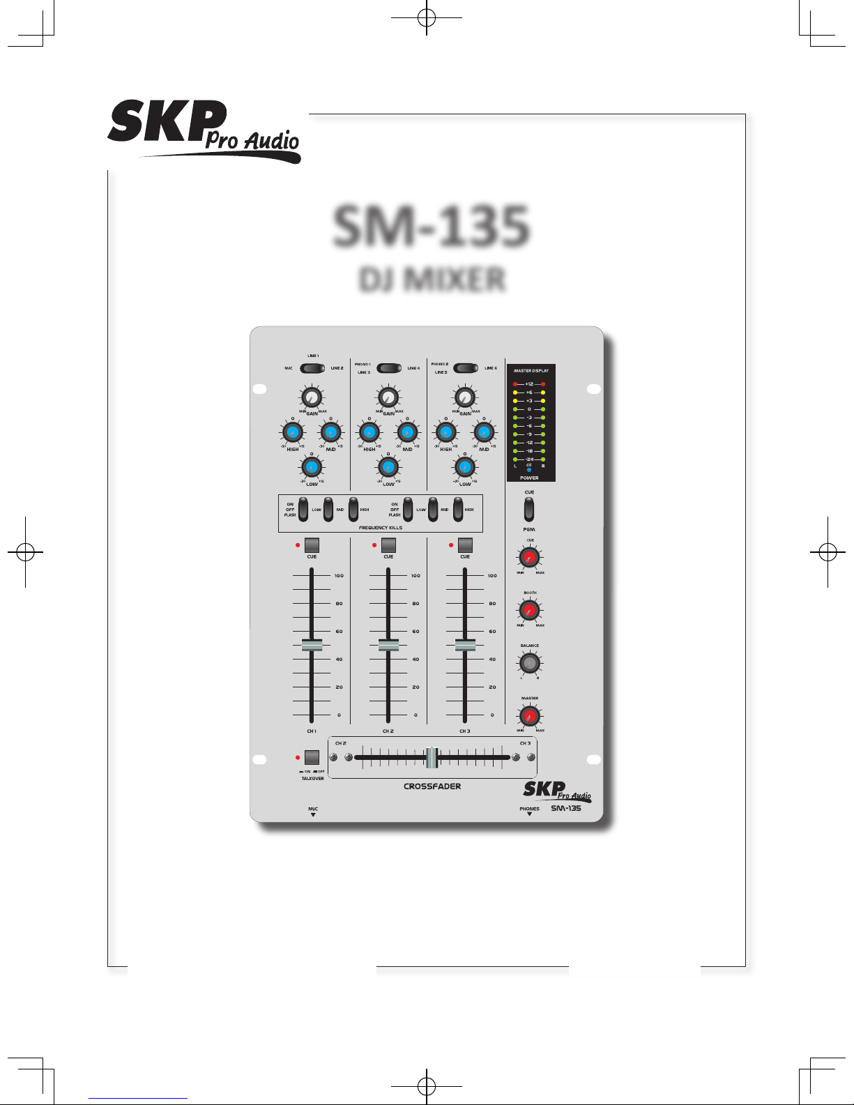
SM-135
DJ MIXER
SM-135.indd 1 2010-3-31 10:48:41

1. Read these instructions before operating this
apparatus.
2. Keep these instructions for future reference.
3. Heed all warnings to ensure safe operation.
4. Follow all instructions provided in this document.
5. Do not use this apparatus near water or in locations
where condensation may occur.
6. Clean only with dry cloth. Do not use aerosol or liquid
cleaners. Unplug this apparatus before cleaning.
7. Do not block any of the ventilation openings. Install
in accordance with the manufacturer
’
s instructions.
8. Do not install near any heat sources such as radiators,
heat registers, stoves, or other apparatus (including
.
9. Do not defeat the safety purpose of the polarized or
grounding-type plug. A polarized plug has two blades
with one wider than the other. A grounding type plug
has two blades and a third grounding prong. The wide
blade or the third prong is provided for your safety. If
the provided plug does not into your outlet, consult
an electrician for replacement of the obsolete outlet.
10. Protect the power cord from being walked on or
pinched particularly at plug, convenience receptacles,
and the point where they exit from the apparatus.
11. Only use attachments/accessories by the
manufacturer.
12. Use only with a cart, stand, tripod, bracket, or
table by the manufacturer, or sold with
the apparatus. When a cart is used, use caution
when moving the cart/apparatus
combination to avoid injury from tip-
over.
13. Unplug this apparatus during lighting
storms or when unused for long
periods of time.
14. Refer all servicing to service personnel.
Servicing is required when the apparatus has been
damaged in any way, such as power-supply cord or
plug is damaged, liquid has been spilled or objects
have fallen into the apparatus, the apparatus has
been exposed to rain or moisture, does not operate
normally, or has been dropped.
IMPORTANT SAFETY INSTRUCTIONS
CAUTION: TO REDUCE THE RISK OF ELECTRIC SHOCK,
DO NOT REMOVE COVER (OR BACK)
NO USER SERVICEABLE PARTS INSIDE
REFER SERVICING TO QUALIFIED PERSONNEL
The lightning flash with arrowhead symbol, within an
equilateral triangle, is intended to alert the user to the
presence of uninsulated
“
dangerous voltage
”
within the
product
’
magnitude to constitute a risk of electric shock to persons.
The exclamation point within an equilateral triangle is in-
tended to alert the user to the presence of important operat-
ing and maintenance (servicing) instructions in the literature
accompanying the appliance.
WARNING: To reduce the risk of or electric shock, do
not expose this apparatus to rain or moisture.
CAUTION: Use of controls or adjustments or performance
of procedures other than those may result in
hazardous radiation exposure.
The apparatus shall not be exposed to dripping or splashing and that no objects with liquids, such as vases,
shall be placed on the apparatus. The MAINS plug is used as the disconnect device, the disconnect device shall
remain readily operable.
Warning: the user shall not place this apparatus in the area during the operation so that the mains switch
can be easily accessible.
CAUTION
RISK OF ELECTRIC SHOCK
DO NOT OPEN
SM-135.indd 2 2010-3-31 10:48:42
- 1 -
INTRODUCTION
Congratulaons on your purchase of the SM DJ Mixer series – SM-135. In order to get the best performance of the SM DJ
Mixer series, please read all safety and owner’s manual carefully before operang the mixer, and keep it in a safe place for
further reference.
FEATURES
1. 3 Channel Professional DJ Mixer
2. Individual Low / Mid / High Kill for Channel 2 & channel 3
3. Talkover with Bright LED
4. Individual Cue with Bright LED
5. Individual Low/Mid/High & Gain Controls
6. Individual Master / Booth / Cue Out Controls
7. XLR Balanced & RCA Unbalanced Out
8. Super long durable crossfader replaceable from above
9. Crossfader for mixing channels 2 and 3 (crossfader assign buon)
10. High-quality smooth channel 100mm faders
11. Cue / Program Switch
12. 6 Line / 2 Phono / 1 Mic Input
13. Master / Booth / Rec / Cue Output
14. Rec-Out independent from master-level for records with stac level
15. 10 Dual Segment Bright LED Meter
16. High Quality Circuit Design
17. High-grade discotheque-mixer with a convincing sound
GETTING STARTED
1. Before turn on the power, set the Master output control on each channel all the way o
2. Always turn the power o before connecng or disconnecng cables
3. Check the AC Voltage before connecng the AC plug
SM-135.indd 1 2010-3-31 10:48:42

- 2 -
1
2
9
8
12
44 4
55 5
3
18
19
17
16
15
14
7
7
7
8 8
6 6 6
10 11
13
28
31
29
32
24
25
26
27
21
22
23
20
Rear View
Top View
Front View
30
9 9
SM-135.indd 2 2010-3-31 10:49:02

- 3 -
1) Mic 1 Socket
Connect the microphone with this 1/4” JACK plug and control the signal via the Mic Level-control. You can adjust the
microphone volume by using the ch-1 fader. Make sure that the MIC/LINE1/LINE2 switch is set to MIC.
2) Talkover Buon
Press this buon if you want to use your microphone. When the buon is pressed, all other signal sources will be aenuated
by 14 dB, so that the microphone can be clearly heard. In the OFF posion, all signals returns to their original level.
3) Mic/Line1/Line2 Switch
Use this switch to select the input to be sent to the individual channel.
4) Gain Control
Use this knob to set the level of input channel.
5) High Control
Used to increase or lower the HIs of the input channel.
6) Middle Control
Used to increase or lower the MIDs of the input channel.
7) Low Control
Used to increase or lower the LOWs of the input channel.
8) Cue Buon
Use this buon in order to select the channel(s) to be monitored. The red LED next to the buon will come up when its
channel is being selected.
9) Channel Fader
Used to adjust the level of each channel.
10) Phono1 & Line3/Line4 Switch
Use this switch to select the input to be sent to the individual channel.
11) Phono2 & Line5/Line6 Switch
Use this switch to select the input to be sent to the individual channel.
12) KILL FREOUENCIES
There aer two ways kill,or cancel out,frequencies,the KILL are on channels CH2 and CH3,using the LOW/MID/HIGH KILL
SWITCHES,each KILL SWITCH has 3 positions:ON(LATCH),OFF&FLASH.When you move the selected KILL SWITCH to the
ON(LATCH) posion,the switch will stay there,and the frequency will killed;When you move the selected KILL SWITCH to
the OFF posion, and the freduency will not be killed;when you move the selected KILL SWITCH to the FLASH posion and
hold it here,the frequency will be killed,releasing the selected KILL SWITCH from the FLASH posion will bring it back to
the OFF posion and the freduency will no longer be killed.
13) Crossfader
Crossfader for mixing channels 2 and 3,If the crossfader is in the center posion, both channels can be heard.
14) Master Level Display
The display shows the level of the le and right master output.
15) Cue / Program select Switch
Connect your headphones to the headphones socket and select the desired channel for monitoring with the Cue buon.
When you set the cue Switch to PGM posion , you can cue the output signal of the mixer; When you set the cue Switch
to CUE posion , you can cue the output signal of the select the channel.
16) Cue Level Control
With this knob, you can adjust the headphones volume without changing the output signal
SM-135.indd 3 2010-3-31 10:49:05
Table of contents
Other SKP Pro Audio Dj Equipment manuals


