SKS Sweden Bonfiglioli Vectron ACTIVE CUBE ACU 201... User manual
www.bonfiglioli.com
Bonfiglioli Riduttori S.p.A.
Via Giovanni XXIII, 7/A
40012 Lippo di Calderara di Reno
Bologna, Italy
tel: +39 051 647 3111
fax: +39 051 647 3126
bonfiglioli@bonfiglioli.com
www.bonfiglioli.com
VEC 521 R3
ACTIVE CUBE
Operating Instructions
Frequency Inverter 230V / 400V
0.25 kW ... 132 kW
Bonfiglioli has been designing and developing innovative
and reliable power transmission and control solutions
for industry, mobile machinery and renewable energy
applications since 1956.

09/08 Operating Instructions ACU 1
General Information about the Documentation
The present documentation refers to the frequency inverters ACTIVE Cube 201 and
ACTIVE Cube 401 series. With their factory settings, both series of devices are suited
for a wide range of applications. The modular hardware and software structure
enables customer-specific adaptation of the frequency inverters. Applications with
high functionality and dynamics requirements can be realized easily.
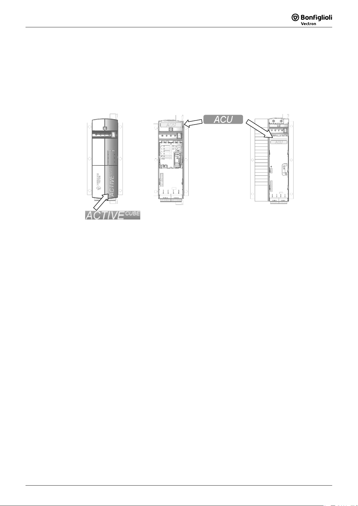
The ACTIVE Cube series can be recognized by its label on the case and the identifica-
tion below the top cover.
(Position of ID
depends on size)
For better clarity, the documentation is structured according to the customer-specific
requirements made on the frequency inverter.
Quick Start Guide
The Quick Start Guide describe the basic steps required for mechanical and electrical
installation of the frequency inverter. The guided commissioning supports you in the
selection of necessary parameters and the configuration of the frequency inverter by
the software.
Operating Instructions
The Operating Instructions describe and document all functions of the frequency
inverter. The parameters required for adapting the frequency inverter to specific ap-
plications as well as the wide range of additional functions are described in detail.
Application Manual
The application manual supplements the documentation for purposeful installation
and commissioning of the frequency inverter. Information on various subjects con-
nected with the use of the frequency inverter are described specific to the applica-
tion.
Installation Instructions
Complementing the Brief Instructions and the Operating Instructions, the Installation
Instructions provide information on how to install and use the additional/optional
components.
If you need a copy of the documentation or additional information, contact your na-
tional representative of BONFIGLIOLI.
Operating Instructions ACU 109/08

2 Operating Instructions ACU
09/08
The following pictograms and signal words are used in the documentation:
Danger!
Danger refers to an immediate threat. Non-compliance with the precaution described
may result in death, serious injury or material damage.
Warning!
Warning refers to a possible threat. Non-compliance with the warning may result in
death, serious injury or material damage.
Caution!
Caution refers to an indirect threat. Non-compliance may result in personal or ma-
terial damage.
Attention!
Attention refers to a possible operational behavior or an undesired condition that can
occur in accordance with the reference text.
Note
Note marks information that facilitates handling for you and supplements the corres-
ponding part of the documentation.
Operating Instructions ACU 09/082

09/08 Operating Instructions ACU 3
TABLE OF CONTENTS
1General Safety Instructions and Information on Use.................................................. 10
1.1General Information ................................................................................. 10
1.2Purpose of the Frequency Inverters ......................................................... 11
1.3Transport and Storage .............................................................................. 11
1.4Handling and Installation ......................................................................... 11
1.5Electrical Connection ................................................................................ 12
1.6Information on Use................................................................................... 12
1.7Maintenance and Service .......................................................................... 12
1.8Safety Instructions on Function „Safe Torque Off“ (STO)........................ 13
2Scope of Supply............................................................................................................ 15
2.1ACU 201 (up to 3.0 kW) and 401 (up to 4.0 kW)...................................... 15
2.2ACU 201 (4.0 to 9.2 kW) and 401 (5.5 to 15.0 kW).................................. 16
2.3ACU 401 (18.5 to 30.0 kW) ....................................................................... 17
2.4ACU 401 (37.0 to 65.0 kW) ....................................................................... 18
2.5ACU 401 (75.0 to 132.0 kW) ..................................................................... 19
3Technical Data.............................................................................................................. 20
3.1General technical data .............................................................................. 20
3.2Technical Data – Control Electronic Equipment ....................................... 21
3.3ACU 201 (0.25 to 1.1 kW, 230 V).............................................................. 22
3.4ACU 201 (1.5 to 3.0 kW, 230 V)................................................................ 23
3.5ACU 201 (4.0 to 9.2 kW, 230 V)................................................................ 24
3.6ACU 401 (0.25 to 1.5 kW, 400 V).............................................................. 25
3.7ACU 401 (1.85 to 4.0 kW, 400 V).............................................................. 26
3.8ACU 401 (5.5 to 15.0 kW, 400 V).............................................................. 27
3.9ACU 401 (18.5 to 30.0 kW, 400 V)............................................................ 28
3.10ACU 401 (37.0 to 65.0 kW, 400 V)............................................................ 29
3.11ACU 401 (75.0 to 132.0 kW, 400 V).......................................................... 30
3.12Operation diagrams .................................................................................. 31
4Mechanical Installation................................................................................................ 32
4.1ACU 201 (up to 3.0 kW) and 401 (up to 4.0 KW) ..................................... 32
4.2ACU 201 (4.0 to 9.2 kW) and 401 (5.5 to 15.0 kW).................................. 33
4.3ACU 401 (18.5 to 30.0 kW) ....................................................................... 34
4.4ACU 401 (37.0 to 65.0 kW) ....................................................................... 35
4.5ACU 401 (75.0 to 132.0 kW) ..................................................................... 36
5Electrical Installation ................................................................................................... 37
5.1EMC Information....................................................................................... 38
5.2Block diagram ........................................................................................... 39
5.3Optional Components ............................................................................... 40
5.4Connection of Unit .................................................................................... 41
Operating Instructions ACU 309/08

4 Operating Instructions ACU
09/08
5.4.1Dimensioning of conductor cross-section ........................................................... 41
5.4.1.1Typical cross-sections ...................................................................................... 41
5.4.2Mains Connection............................................................................................ 42
5.4.3Motor Connection............................................................................................ 43
5.4.3.1Length of motor cables, without filter................................................................ 43
5.4.3.2Motor cable length, with output filter dU/dt ....................................................... 43
5.4.3.3Motor cable length, with sinus filter .................................................................. 43
5.4.3.4Group drive .................................................................................................... 44
5.4.3.5Speed sensor connection ................................................................................. 44
5.4.4Connection of a Brake Resistor......................................................................... 44
5.5Connection of types .................................................................................. 45
5.5.1ACU 201 (up to 3.0 kW) and 401 (up to 4.0 kW)................................................ 45
5.5.2ACU 201 (4.0 to 9.2 kW) and 401 (5.5 to 15.0 kW) ............................................ 47
5.5.3ACU 401 (18.5 to 30.0 kW) .............................................................................. 49
5.5.4ACU 401 (37.0 to 65.0 kW) .............................................................................. 51
5.5.5ACU 401 (75.0 to 132.0 kW) ............................................................................ 53
5.6Control Terminals...................................................................................... 55
5.6.1External DC 24 V power supply......................................................................... 57
5.6.2Relay Output .................................................................................................. 57
5.6.3Motor Thermo-Contact..................................................................................... 57
5.6.4Control terminals – Connection diagrams of configurations ................................. 58
5.7Configurations overview........................................................................... 58
5.7.1Configuration 110 – Sensorless Control ............................................................. 59
5.7.2Configuration 111 – Sensorless Control with Technology Controller...................... 59
5.7.3Configuration 410 – Sensorless Field-Oriented Control........................................ 60
5.7.4Configuration 411 – Sensorless Field-Oriented Control with Technology ..................
Controller ....................................................................................................... 61
5.7.5Configuration 430 – Sensorless Field-Oriented Control, Speed and Torque ..............
Controlled....................................................................................................... 62
5.7.6Configuration 210 – Field-Oriented Control, Speed Controlled ............................. 63
5.7.7Configuration 211 – Field-Oriented Control with Technology Controller ............... 63
5.7.8Configuration 230 – Field-Orientated Control, Speed and Torque Controlled ......... 64
5.7.9Configuration 510 – Field-Oriented Control of Synchronous Machine, ......................
Speed Controlled............................................................................................. 65
5.7.10Configuration 530 – Field-Orientated Control of a Synchronous Machine, ................
Speed and Torque Controlled ........................................................................... 66
6Control Unit KP500 ...................................................................................................... 67
6.1Menu Structure ......................................................................................... 68
6.2Main Menu................................................................................................. 68
6.3Actual Value Menu (VAL) .......................................................................... 69
6.4Parameter Menu (PARA)........................................................................... 70
6.5Copy Menu (CPY) ...................................................................................... 71
6.5.1Reading the Stored Information........................................................................ 71
6.5.2Menu Structure ............................................................................................... 72
6.5.3Selecting the Source........................................................................................ 72
6.5.4Selecting the Destination ................................................................................. 73
6.5.5Copy Operation............................................................................................... 73
6.5.6Error Messages ............................................................................................... 74
6.6Reading Data From Control Unit............................................................... 75
6.6.1Activation ....................................................................................................... 75
6.6.2Data transfer .................................................................................................. 76
6.6.3Resetting to Normal Operation ......................................................................... 77
6.7Control Menu (CTRL) ................................................................................ 77
6.8Controlling the Motor via the Control Unit ............................................... 78
Operating Instructions ACU 09/084

09/08 Operating Instructions ACU 5
7Commissioning of the Frequency Inverter................................................................... 81
7.1Switching on Mains Voltage...................................................................... 81
7.2Setup Using the Control Unit .................................................................... 81
7.2.1Configuration.................................................................................................. 82
7.2.2Data Set......................................................................................................... 83
7.2.3Motor Type..................................................................................................... 84
7.2.4Machine Data.................................................................................................. 84
7.2.5Plausibility check ............................................................................................. 85
7.2.6Parameter identification ................................................................................... 87
7.2.7Application data .............................................................................................. 89
7.2.7.1Acceleration and deceleration deceleration deceleration...................................... 89
7.2.7.2Set points at multi-functional input ................................................................... 90
7.2.8Quitting commissioning.................................................................................... 90
7.2.9Selection of an actual value for display.............................................................. 91
7.3Check direction of rotation ....................................................................... 91
7.4Speed sensor............................................................................................. 92
7.4.1Speed sensor 1 ............................................................................................... 92
7.4.2Speed sensor 2 ............................................................................................... 93
7.5Set-up via the Communication Interface ................................................. 94
8Inverter Data ............................................................................................................... 97
8.1Serial Number ........................................................................................... 97
8.2Optional Modules ...................................................................................... 97
8.3Inverter Software Version ........................................................................ 97
8.4Set Password ............................................................................................ 97
8.5Control Level ............................................................................................. 98
8.6User Name................................................................................................. 98
8.7Configuration ............................................................................................ 98
8.8Language ................................................................................................ 101
8.9Programming .......................................................................................... 101
9Machine Data ............................................................................................................. 102
9.1Rated Motor Parameters......................................................................... 102
9.2Further motor parameters ...................................................................... 103
9.2.1Stator Resistance .......................................................................................... 103
9.2.2Leakage Coefficient ....................................................................................... 103
9.2.3Magnetizing Current ...................................................................................... 104
9.2.4Rated slip correction factor ............................................................................ 104
9.2.5Voltage constant ........................................................................................... 105
9.2.6Stator inductance .......................................................................................... 105
9.2.7Peak current ................................................................................................. 105
9.2.8Change sense of rotation ............................................................................... 106
9.3Internal values........................................................................................ 106
9.4Speed Sensor 1 ....................................................................................... 107
9.4.1Operation Mode Speed Sensor 1..................................................................... 107
9.4.2Division marks, speed sensor 1....................................................................... 109
9.4.3Gear factor speed sensor 1 ............................................................................ 110
9.5Sensor evaluation ................................................................................... 111
Operating Instructions ACU 509/08

6 Operating Instructions ACU
09/08
10System Data ............................................................................................................... 112
10.1Actual System Value ............................................................................... 112
10.2Volume Flow and Pressure...................................................................... 112
11Operational Behavior ................................................................................................. 113
11.1Starting Behavior .................................................................................... 113
11.1.1Starting Behavior of Sensorless Control System................................................ 113
11.1.1.1Starting Current ............................................................................................ 115
11.1.1.2Frequency Limit ............................................................................................ 115
11.1.1.3Brake release time ........................................................................................ 115
11.1.2Flux Formation.............................................................................................. 116
11.2Stopping Behavior................................................................................... 117
11.2.1Switch-Off Threshold ..................................................................................... 119
11.2.2Holding Time ................................................................................................ 119
11.3Direct current brake................................................................................ 119
11.4Auto Start................................................................................................ 120
11.5Search Run.............................................................................................. 121
11.6Positioning .............................................................................................. 122
11.6.1Reference Positioning .................................................................................... 123
11.6.2Axle Positioning............................................................................................. 126
12Error and warning behavior ....................................................................................... 129
12.1Overload Ixt ............................................................................................ 129
12.2Temperature ........................................................................................... 129
12.3Controller status ..................................................................................... 130
12.4IDC Compensation Limit ......................................................................... 130
12.5Frequency Switch-Off Limit .................................................................... 131
12.6Motor Temperature................................................................................. 131
12.7Phase Failure........................................................................................... 132
12.8Automatic Error Acknowledgment.......................................................... 133
13Reference Values........................................................................................................ 134
13.1Frequency Limits..................................................................................... 134
13.2Slip Frequency......................................................................................... 134
13.3Percentage Value Limits ......................................................................... 134
13.4Frequency reference channel.................................................................. 135
13.4.1Block diagram............................................................................................... 136
13.5Reference percentage channel ............................................................... 138
13.5.1Block diagram............................................................................................... 138
13.6Fixed reference values............................................................................ 140
13.6.1Fixed Frequencies ......................................................................................... 140
13.6.2JOG frequency .............................................................................................. 141
13.6.3Fixed Percentages ......................................................................................... 141
13.7Frequency ramps .................................................................................... 142
13.8Percentage Value Ramps ........................................................................ 145
13.9Block Frequencies ................................................................................... 145
Operating Instructions ACU 09/086

09/08 Operating Instructions ACU 7
13.10Motor Potentiometer .............................................................................. 146
13.10.1Motorpoti (MP).............................................................................................. 147
13.10.2Motorpoti (KP) .............................................................................................. 147
13.10.3Controlling the Motor via the Control Unit........................................................ 148
13.11PWM-/repetition frequency input .......................................................... 149
14Control Inputs and Outputs ....................................................................................... 151
14.1Multi-Function Input MFI1 ..................................................................... 151
14.1.1Analog input MFI1A....................................................................................... 151
14.1.1.1Characteristic................................................................................................ 151
14.1.1.2Scaling ......................................................................................................... 153
14.1.1.3Tolerance Band and Hysteresis....................................................................... 153
14.1.1.4Filter Time Constant ...................................................................................... 154
14.1.1.5Error and warning behavior............................................................................ 155
14.2Multi-Function Output MFO1 .................................................................. 156
14.2.1Analog output MFO1A.................................................................................... 156
14.2.1.1Output Characteristic..................................................................................... 157
14.2.2Frequency Output MFO1F .............................................................................. 157
14.2.2.1Scaling ......................................................................................................... 157
14.3Digital Outputs........................................................................................ 158
14.3.1Digital Signal ................................................................................................ 161
14.3.2Setting Frequency ......................................................................................... 162
14.3.3Reference value reached................................................................................ 163
14.3.4Flux Forming finished .................................................................................... 164
14.3.5Brake release................................................................................................ 164
14.3.6Current Limitation ......................................................................................... 164
14.3.7External Fan ................................................................................................. 164
14.3.8Warning Mask............................................................................................... 165
14.3.9Application warning mask .............................................................................. 167
14.4Digital inputs........................................................................................... 168
14.4.1Start command ............................................................................................. 173
14.4.23-wire control ............................................................................................... 173
14.4.3Error Acknowledgment .................................................................................. 174
14.4.4Timer........................................................................................................... 174
14.4.5Thermo contact............................................................................................. 174
14.4.6n-/M Control Change-Over ............................................................................. 174
14.4.7Data Set Change-Over................................................................................... 175
14.4.8Fixed Value Change-Over............................................................................... 176
14.4.9Motor Potentiometer...................................................................................... 176
14.4.10Handshake Traverse Function ........................................................................ 177
14.4.11External error ............................................................................................... 177
14.5Function Modules.................................................................................... 178
14.5.1Timer........................................................................................................... 178
14.5.1.1Timer – Time Constant .................................................................................. 179
14.5.2Comparator .................................................................................................. 181
14.5.3Function table............................................................................................... 182
14.5.4Multiplexer/Demultiplexer .............................................................................. 183
15V/f-Characteristic ...................................................................................................... 185
15.1Dynamic Voltage Pre-Control ................................................................. 186
16Control Functions ....................................................................................................... 187
16.1Intelligent current limits ........................................................................ 187
16.2Voltage controller ................................................................................... 188
16.3Technology Controller............................................................................. 193
Operating Instructions ACU 709/08

8 Operating Instructions ACU
09/08
16.4Functions of Sensorless Control.............................................................. 202
16.4.1Slip compensation ......................................................................................... 202
16.4.2Current limit value controller .......................................................................... 202
16.5Functions of Field-Orientated Control .................................................... 203
16.5.1Current Controller ......................................................................................... 203
16.5.2Torque Controller .......................................................................................... 205
16.5.2.1Limit Value Sources ....................................................................................... 205
16.5.3Speed controller............................................................................................ 206
16.5.3.1Limitation of Speed Controller ........................................................................ 208
16.5.3.2Limit Value Sources ....................................................................................... 209
16.5.3.3Integral time speed synchronization................................................................ 209
16.5.4Acceleration Pre-Control ................................................................................ 209
16.5.5Field Controller ............................................................................................. 210
16.5.5.1Limitation of field controller............................................................................ 211
16.5.6Modulation Controller .................................................................................... 212
16.5.6.1Limitation of Modulation Controller ................................................................. 213
17Special Functions ....................................................................................................... 214
17.1Pulse Width Modulation.......................................................................... 214
17.2Fan .......................................................................................................... 215
17.3Bus controller.......................................................................................... 215
17.4Brake Chopper and Brake Resistance..................................................... 217
17.4.1Dimensioning of Brake Resistor ...................................................................... 218
17.5Motor Protection Switch ......................................................................... 219
17.6V-belt Monitoring.................................................................................... 221
17.7Functions of Field-Orientated Control .................................................... 221
17.7.1Motor Chopper.............................................................................................. 221
17.7.2Temperature Adjustment ............................................................................... 222
17.7.3Speed Sensor Monitoring ............................................................................... 224
17.8Traverse function.................................................................................... 225
18Actual Values.............................................................................................................. 227
18.1Actual Values of the Frequency Inverter ................................................ 227
18.1.1STO Status ................................................................................................... 229
18.2Actual Values of the Machine.................................................................. 230
18.3Actual value memory .............................................................................. 231
18.4Actual Values of the System ................................................................... 232
18.4.1Actual System Value...................................................................................... 232
18.4.2Volume Flow and Pressure ............................................................................. 233
19Error Protocol ............................................................................................................. 234
19.1Error List ................................................................................................. 234
19.1.1Error Messages ............................................................................................. 234
19.2Error Environment .................................................................................. 237
20Operational and Error Diagnosis................................................................................ 239
20.1Status Display ......................................................................................... 239
20.2Status of Digital Signals.......................................................................... 239
20.3Controller Status..................................................................................... 240
20.4Warning Status and Warning Status Application ................................... 241
Operating Instructions ACU 09/088

09/08 Operating Instructions ACU 9
21Parameter List............................................................................................................ 243
21.1Actual Value Menu (VAL) ........................................................................ 243
21.2Parameter Menu (PARA)......................................................................... 246
Index ................................................................................................................................ 254
Functions of the control terminals (table) ....................................................................... 256
Operating Instructions ACU 909/08

10 Operating Instructions ACU
09/08
1General Safety Instructions and Information on Use
Warning! The specifications and instructions contained in the documentation
must be complied with strictly during installation and commissioning.
Only qualified staff who has read the documentation and, in particular,
the safety instructions carefully is allowed to carry out installation or
commissioning work or to operate the frequency inverters. The term
„Qualified Staff“ refers to anybody who is familiar with the installation,
assembly, commissioning and operation of the frequency inverter and
has the proper qualification for the job.
The present documentation was prepared with great care and it was subjected to
extensive and repeated reviews. For reasons of clarity, it was not possible to include
all details of all types of the product in the documentation. Neither was it possible to
consider all conceivable installation, operation or maintenance situations. If you re-
quire further information or if you meet with specific problems which are not dealt
with in sufficient detail in the documentation, contact your national BONFIGLIOLI
agent.
We would also like to point out that the contents of this documentation do not form
part of any previous or existing agreement, assurance or legal relationship. Neither
are they intended to supplement or replace such agreements, assurances or legal
relationships. The manufacturer's obligations are exclusively specified in the relevant
purchase contract. This contract also contains all and any warranty regulations which
may apply to the relevant scope of supply. These contractual warranty provisions are
neither extended nor limited by the specifications contained in this documentation.
The manufacturer reserves the right to correct or amend the specifications, product
information and omissions in these operating instructions without notice. The manu-
facturer shall not be liable for any damage, injuries or costs which may be caused by
the aforementioned reasons.
1.1 General Information
Warning! The DC-link circuit of the frequency inverter is charged during opera-
tion, i.e. there is always the risk of contact with high voltage. Frequency
inverters are used for driving moving parts and they may become hot at
the surface during operation.
Any unauthorized removal of the necessary covers, improper use,
wrong installation or operation may result in serious injuries or material
damage.
In order to avoid such injuries or damage, only qualified staff may carry
out the transport, installation, setup or maintenance work required. The
standards EN 50178, IEC 60364 (Cenelec HD 384 or DIN VDE 0100),
IEC 60664-1 (Cenelec HD 625 or VDE 0110-1), BGV A2 (VBG 4) as well
as the applicable national regulations must be complied with. The term
„Qualified Staff“ refers to anybody who is familiar with the installation,
assembly, commissioning and operation of the frequency inverter as
well as the possible hazards and has the proper qualification for the job.
Operating Instructions ACU 09/0810

09/08 Operating Instructions ACU 11
1.2 Purpose of the Frequency Inverters
Warning! The frequency inverters are electrical drive components intended for
installation in industrial plants or machines. Commissioning and start of
operation is not allowed until it has been verified that the plant meets
the requirements of the EC Machinery Directive 98/37/EEC and EN
60204. In accordance with the CE marking requirements, the frequency
inverters also comply with the Low Voltage Directive 2006/95/EC as
well as EN 50178/DIN VDE 0160 and EN 61800-2. The user shall be
responsible for making sure that the requirements of the EMC Directive
89/336/EEC are met. Frequency inverters are only available at specia-
lized dealers and are exclusively intended for professional use as per EN
61000-3-2.
The frequency inverters are also marked with the UL label according to
UL508c, which proves that they also meet the requirements of the CSA
Standard C22.2-No. 14-95.
The technical data, connection specifications and information on am-
bient conditions are indicated on the name plate and in the documenta-
tion and must be complied with in any case. Anyone involved in any
kind of work at the device must have read the instructions carefully and
understood them before starting the work.
Do not connect any capacitive loads.
1.3 Transport and Storage
The frequency inverters must be transported and stored in an appropriate way. Dur-
ing transport and storage the devices must remain in their original packaging. The
units may only be stored in dry rooms which are protected against dust and moisture
and are exposed to little temperature deviations only. Observe the climatic conditions
according to EN 50178 and the marking on the packaging. The frequency inverters
must not be stored for more than one year without connecting them to nominal vol-
tage.
1.4 Handling and Installation
Warning! Damaged or destroyed components must not be put into operation
because they may be a health hazard.
The frequency inverters are to be used in accordance with the documentation as well
as the applicable directives and standards. They must be handled carefully and pro-
tected against mechanical stress. Do not bend any components or change the isolat-
ing distances. Do not touch electronic components or contacts. The devices are
equipped with components which are sensitive to electrostatic energy and can easily
be damaged if handled improperly. Any use of damaged or destroyed components
shall be considered as a non-compliance with the applicable standards. Do not re-
move any warning signs from the device.
Operating Instructions ACU 1109/08

12 Operating Instructions ACU
09/08
1.5 Electrical Connection
Warning! Before any assembly or connection work, discharge the frequency in-
verter. Verify that the frequency inverter is discharged.
Do not touch the terminals because the capacitors may still be charged.
Comply with the information given in the operating instructions and on
the frequency inverter label.
When working at the frequency inverters, comply with the applicable standards BGV
A2 (VBG 4), VDE 0100 and other national directives. Comply with the electrical instal-
lation instructions given in the documentation as well as the relevant directives. The
manufacturer of the industrial machine or plant is responsible for making sure that
the limit values specified in the EMC product standard EN 61800-3 for electrical vari-
able-speed drives are complied with. The documentation contains information on
EMC-conforming installation. The cables connected to the frequency inverters may
not be subjected to high-voltage insulation tests unless appropriate circuitry meas-
ures are taken before.
1.6 Information on Use
Warning! The frequency inverter may be connected to power supply every 60 s.
This must be considered when operating a mains contactor in jog oper-
ation mode. For commissioning or after an emergency stop, a non-
recurrent, direct restart is permissible.
After a failure and restoration of the power supply, the motor may start
unexpectedly if the AutoStart function is activated.
If staff is endangered, a restart of the motor must be prevented by
means of external circuitry.
Before commissioning and the start of the operation, make sure to fix
all covers and check the terminals. Check the additional monitoring and
protective devices according to EN 60204 and applicable the safety
directives (e.g. Working Machines Act, Accident Prevention Directives
etc.).
No connection work may be performed, while the system is in opera-
tion.
1.7 Maintenance and Service
Warning! Unauthorized opening and improper interventions can lead to personal
injury or material damage. Repairs on the frequency inverters may only
be carried out by the manufacturer or persons authorized by the manu-
facturer. Check protective equipment regularly.
Operating Instructions ACU 09/0812

09/08 Operating Instructions ACU 13
1.8 Safety Instructions on Function „Safe Torque Off“ (STO)
The function „Safe Torque Off“ (STO) is a functional safety provision, i.e. it protects
staff from damage, provided that projecting, installation and operation are performed
properly. This function does not disconnect the plant from power supply.
To disconnect the plant from power supply (for example for service purposes) an
„Emergency Stop“ circuit according to EN 60204 has to be installed.
For maintenance work, a provision must be provided for disconnecting the plant from
power supply.
Warning! Improper installation of the safety circuitry may result in uncontrolled
starting of the drive. This may cause death, serious injuries and signifi-
cant material damage.
Safety functions may only be installed and commissioned by qualified
staff.
The STO function is not suitable for emergency stop as per EN 60204.
An emergency stop can be realized by installing a mains contactor.
An emergency stop according to EN 60204 must be functioning in all
operation modes of the frequency inverter. Resetting of an emergency
stop must not result in uncontrolled starting of the drive.
The drive is started again when the function STO is no longer required.
In order to comply with EN 60204, it must be ensured by taking exter-
nal measures that the drive does not start without prior confirmation.
Without a mechanical brake, the drive will not stop immediately but
coast to a standstill. If this may result in personal or material damage,
additional safety measures must be taken.
If persons may be endangered after disconnection of the motor power
supply by STO, access to the hazard areas must be prevented until the
drive has stopped.
Check the safety function at regular intervals according to the results of
your risk analysis.
BONFIGLIOLI VECTRON recommends that the check is performed after
one year, at the latest.
The STO function is fail-safe. However, on rare occasions, the occur-
rence of component defects may cause jerking of the motor shaft (max.
180°/pole pair, e.g. jerk by 90° with 4-pole motor, 180°/2). It must be
checked if this causes a dangerous movement of the plant.
If the STO function is used, the special safety, installation and instruc-
tions on use instructions shall be complied with.
Operating Instructions ACU 1309/08

14 Operating Instructions ACU
09/08
Warning! Dangerous voltage!
The safety function “Safe Torque Off ” may only be used if mechanical
work is to be performed on the driven machines, not for work on live
components.
After disconnection of an external DC 24 V power supply, the DC link of
the frequency inverter is still connected to mains supply.
Even if power supply to the motor is disconnected, and the motor is
coasting to a standstill or has already stopped, high voltages may still
be present on the motor terminals.
Before working (e.g. maintenance) on live parts, the plant must always
be disconnected from mains supply (main switch). This must be docu-
mented on the plant.
When the function “Safe Torque Off ” is triggered, the motor is not
isolated from the DC link of the frequency inverter. High voltage levels
may be present at the motor.
Do not touch live terminals.
Operating Instructions ACU 09/0814
09/08 Operating Instructions ACU 15
2Scope of Supply
Thanks to the modular hardware components, the frequency inverters can be inte-
grated in the automation concept easily. The scope of delivery described can be sup-
plemented by optional components and adapted to the customer-specific require-
ments. The plug-in type connection terminals enable a safe function and quick and
easy assembly.
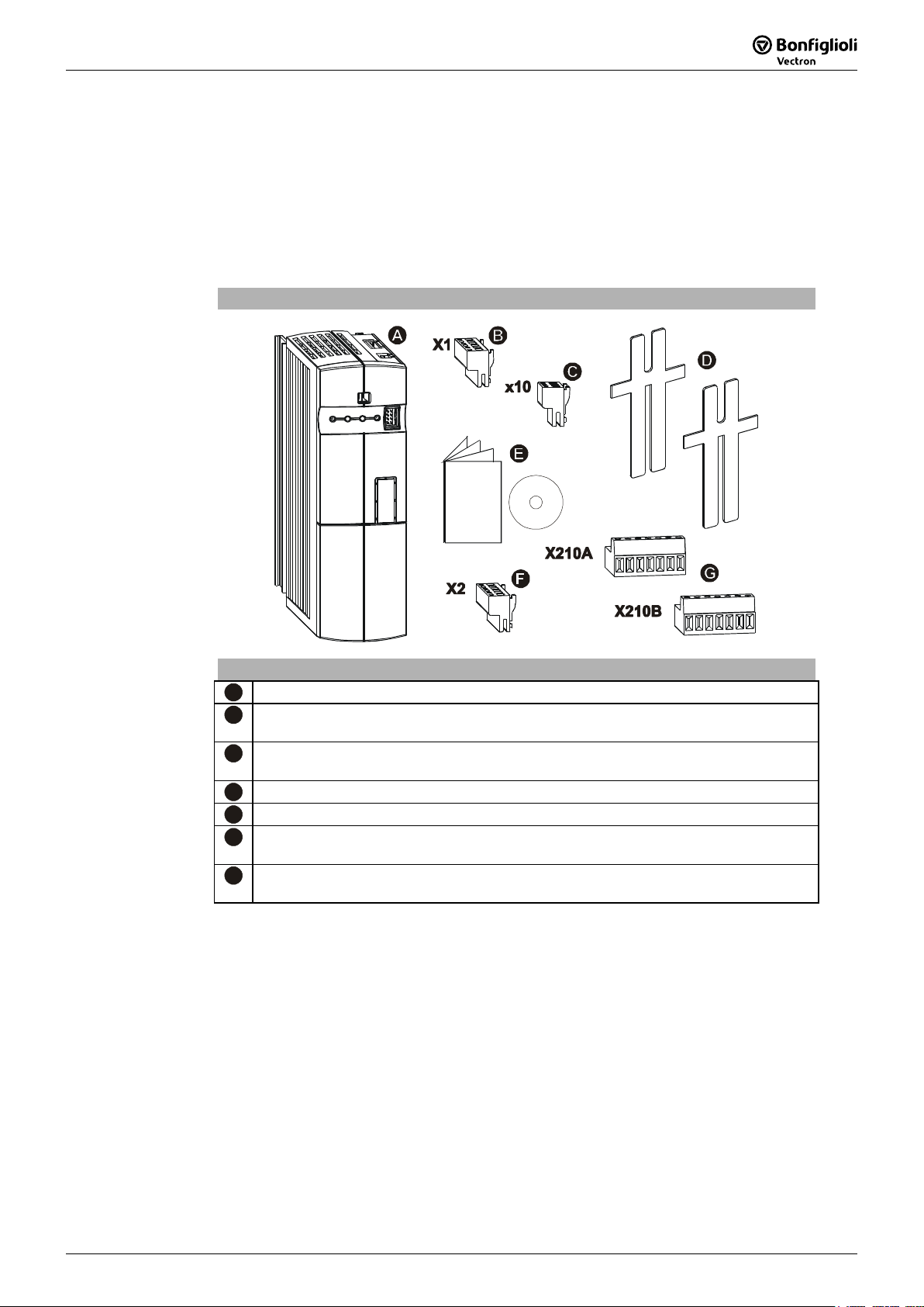
2.1 ACU 201 (up to 3.0 kW) and 401 (up to 4.0 kW)
Scope of Supply
Scope of Supply
A
Frequency inverter
B
Terminal strip X1 (Phoenix ZEC 1,5/ST7,5)
Plug-in terminals for mains connection and DC linking
C
Terminal strip X10 (Phoenix ZEC 1.5/3ST5.0)
Plug-in terminals for the relay output
D
Standard fixtures for vertical assembly
E
Brief Instructions and Operating Instructions on CD ROM
F
Terminal strip X2 (Phoenix ZEC 1,5/ST7,5)
Plug-in terminal for brake resistor and motor connection
G
Control terminals X210A / X210B (Wieland DST85 / RM3.5)
Plug-in terminal for connection of the control signals
Note: Please check incoming goods for quality, quantity and nature without
delay. Obvious defects such as exterior damage of the packing and/or the
unit must be notified to the sender within seven days for insurance rea-
sons.
Operating Instructions ACU 1509/08

16 Operating Instructions ACU
09/08
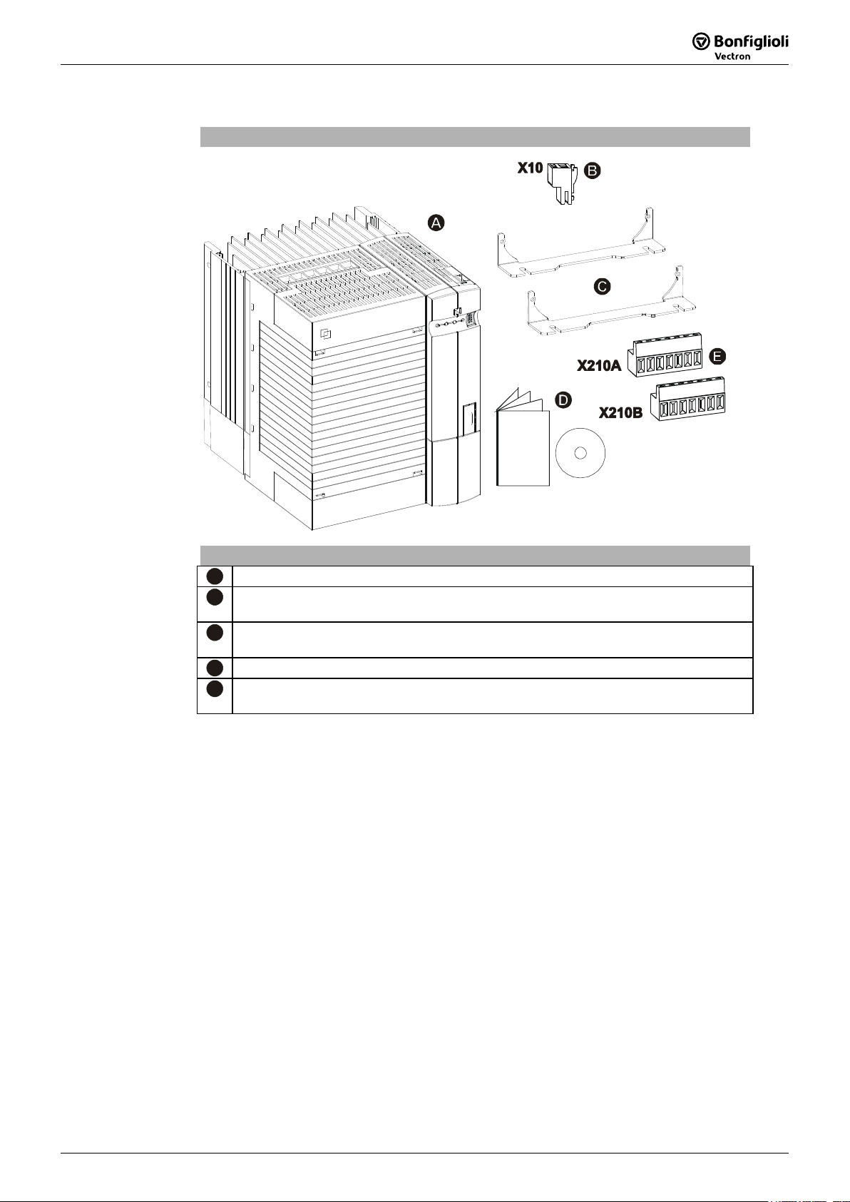
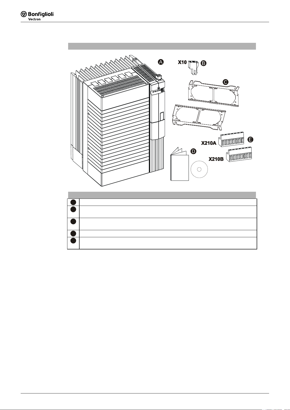
2.2 ACU 201 (4.0 to 9.2 kW) and 401 (5.5 to 15.0 kW)
Scope of Supply
Scope of Supply
A
Frequency inverter
B
Terminal strip X10 (Phoenix ZEC 1.5/3ST5.0)
Plug-in terminals for the relay output
C
Standard fittings with fitting screws (M4x20, M4x60)
for vertical assembly
D
Brief Instructions and Operating Instructions on CD ROM
E
Control terminals X210A / X210B (Wieland DST85 / RM3.5)
Plug-in terminal for connection of the control signals
Note: Please check incoming goods for quality, quantity and nature without
delay. Obvious defects such as exterior damage of the packing and/or the
unit must be notified to the sender within seven days for insurance rea-
sons.
Operating Instructions ACU 09/0816
09/08 Operating Instructions ACU 17
2.3 ACU 401 (18.5 to 30.0 kW)
Scope of Supply
Scope of Supply
A
Frequency inverter
B
Terminal strip X10 (Phoenix ZEC 1.5/3ST5.0)
Plug-in terminals for the relay output
C
Standard fittings with fitting screws (M4x20, M4x70)
for vertical assembly
D
Brief Instructions and Operating Instructions on CD ROM
E
Control terminals X210A / X210B (Wieland DST85 / RM3.5)
Plug-in terminal for connection of the control signals
Note: Please check incoming goods for quality, quantity and nature without
delay. Obvious defects such as exterior damage of the packing and/or the
unit must be notified to the sender within seven days for insurance rea-
sons.
Operating Instructions ACU 1709/08
18 Operating Instructions ACU
09/08
2.4 ACU 401 (37.0 to 65.0 kW)
Scope of Supply
Scope of Supply
A
Frequency inverter
B
Terminal strip X10 (Phoenix ZEC 1.5/3ST5.0)
Plug-in terminals for the relay output
C
Standard fittings with fitting screws (M5x20)
for vertical assembly
D
Brief Instructions and Operating Instructions on CD ROM
E
Control terminals X210A / X210B (Wieland DST85 / RM3.5)
Plug-in terminal for connection of the control signals
Note: Please check incoming goods for quality, quantity and nature without
delay. Obvious defects such as exterior damage of the packing and/or the
unit must be notified to the sender within seven days for insurance rea-
sons.
Operating Instructions ACU 09/0818
This manual suits for next models
1
Table of contents
Popular Inverter manuals by other brands


CyberPower
CyberPower POWERTRIP 480 user manual

Pedal Power Generators
Pedal Power Generators Bike Stand Plate Attachment Procedure

Vector
Vector Maxx SST VEC043 Owner's manual & warranty

Omnik
Omnik Omniksol-2k-TL3-S user manual

DAB PUMPS LTD.
DAB PUMPS LTD. SUNDRIVER quick guide

Solenso
Solenso SLT Quick installation guide


