manuals.online logo
Brands
  1. Home
  2. •
  3. Brands
  4. •
  5. ABB
  6. •
  7. Inverter
  8. •
  9. ABB PVI-3.0-TL-OUT User manual

ABB PVI-3.0-TL-OUT User manual

In addition to what is explained below, the safety and installation information provided in the
installation manual must be read and followed. The technical documentation and the interface
and management software for the product are available at the website.
The device must be used in the manner described in the manual. If this is not the case the
safety devices guaranteed by the inverter might be ineffective.
Quick Installation Guide
PVI-3.0/3.6/4.2-TL-OUTD
ABB Solar inverters
1.
Labels and SymbolsInverter Models and Components
2.
Lifting and transport
4.
Choice of installation location
EN
Assembly Instruction
6.
List of supplied components
3.
Choice of installation location
5.
,QSXWFRQ¿JXUDWLRQ'&
7.
7KHODEHOVRQWKHLQYHUWHUKDYHWKH$JHQF\PDUNLQJPDLQWHFKQLFDOGDWDDQGLGHQWL¿FDWLRQRIWKHHTXLSPHQWDQGPDQXIDFWXUHU
V
dc max
I
dc max
V
dc MPP
V
dc, Full Power
I
sc max
V
acr
f
r
I
ac max
P
acr (cos
ij
=
±0.9)
P
acr (cos
ij
=1)
MODEL:
PVI-3.0-TL-OUTD
IP65
5 minutes
600 V
90 - 580 V
2 x 10 A
160 - 530 V
2 x 12.5 A
Made in Italy
DIN V VDE 0126-1-1
PROTECTIVE CLASS: I
230 V 1Ø
50 Hz
3000W @ 45°C amb.
3000 W @ 50°C amb.
14.5 A
-25 to +60 °C
-13 to +140 °F
SOLAR INVERTER
www.abb.com/solar
V
dc max
I
dc max
V
dc MPP
V
dc, Full Power
I
sc max
V
acr
f
r
I
ac max
P
acr (cos
ij
=
±0.9)
P
acr (cos
ij
=1)
MODEL:
PVI-3.6-TL-OUTD
IP65
5 minutes
600 V
90 - 580 V
2 x 16 A
120 - 530 V
2 x 20 A
Made in Italy
DIN V VDE 0126-1-1
PROTECTIVE CLASS: I
230 V 1Ø
50 Hz
3600W @ 50°C amb.
3600 W @ 55°C amb.
17.2 A(*)
(*): 16 A for UK G83 Version
-25 to +60 °C
-13 to +140 °F
SOLAR INVERTER
www.abb.com/solar
V
dc max
I
dc max
V
dc MPP
V
dc, Full Power
I
sc max
V
acr
f
r
I
ac max
P
acr (cos
ij
=
±0.9)
P
acr (cos
ij
=1)
MODEL:
PVI-4.2-TL-OUTD
IP65
5 minutes
600 V
90 - 580 V
2 x 16 A
140 - 530 V
2 x 20 A
Made in Italy
DIN V VDE 0126-1-1
PROTECTIVE CLASS: I
230 V 1Ø
50 Hz
4200W @ 45°C amb.
4200 W @ 50°C amb.
20 A
-25 to +60 °C
-13 to +140 °F
SOLAR INVERTER
www.abb.com/solar
The labels attached to the equipment must NOT be removed, damaged, dirtied, hidden,etc...
,IWKHVHUYLFHSDVVZRUGLVUHTXHVWHGWKH¿HOGWREHXVHGLVWKHVHULDOQXPEHU61<<::666666
,QWKHPDQXDODQGRULQVRPHFDVHVRQWKHHTXLSPHQWWKHGDQJHURUKD]DUG]RQHVDUHLQGLFDWHGZLWKVLJQVODEHOVV\PEROVRULFRQV
Always refer to instruction
manual General warning - Important
safety information +D]DUGRXVYROWDJH Hot surfaces
IP65
Protection rating of
HTXLSPHQW Temperature range Without isolation
transformer Direct and alternating
currents, respectively
Positive pole and negative
pole of the input voltage
(DC)
Always use safety clothing
and/or personal safety
devices
Point of connection for
grounding protection Time need to discharge
stored energy
10
01
Inverter model
02
Inverter Part Number
03
Inverter Serial Number
04
Week/Year of manufacture
PVI-X.X-TL-OUTD-Y
P/N:PPPPPPPPPPP
WO:XXXXXXX
SO:SXXXXXXXX Q1
SN:YYWWSSSSSS WK:WWYY
01
02
04
03
The models of inverter to which this guide refers are available in 3 power ratings: 3.0 kW, 3.6 kW and 4.2 kW.
The only difference in terms of components between the three power levels is the number of input connectors: 2 pairs in PVI-3.0/3.6-TL-OUTD models; 3 (2x MPPT1
and 1x MPPT2) pairs in PVI-4.2-TL-OUTD models. Two types are available for each model: Standard or with DC disconnect switch (Version -S).
STANDARD VERSION - S VERSION
01
03
02
04
05 06 07 08
17 18 19 20
1509 10 11 12 13 14
1716 18 19 20
1509 10 11 12 13 14
UNO
POWERALARMGFI
ESC UP DOWN ENTER
Main components
01
Bracket
05
Front cover
09
DC Input terminal block
13
Signal terminal block
17
Input connectors (MPPT1)
02
Locking screw
06
LED Panel
10
AC Output terminal block
14
RJ45 Connectors
18
Input connectors (MPPT2)
03
Heat sink
07
Display
11
&KDQQHOFRQ¿JXUDWLRQVZLWFK
15
RS485 line termination switch
19
AC cable gland
04
DSP Reprogramming
connectors
08
Keyboard
12
Internal battery
16
DC Disconnect switch
20
Service cable glands
Available components Quantity
Bracket for wall mounting 1
Bolts and screws for wall mounting 2 + 2
M6x10 screw 1
D.18 Washer 3
L-key, TORX TX20 1
M20 Cable gland 1
M25 Cable gland 1
Available components Quantity
Two-hole gasket for M20 signal cable
glands and cap TGM58 1 + 1
-XPSHUVIRUFRQ¿JXUDWLRQRIWKH
parallel input channels 2
Connector for the connection of the
communication and control signals 2
0DOHTXLFN¿WFRQQHFWRUV
2 (3.0/3.6 kW)
3 (4.2 kW)
)HPDOHTXLFN¿WFRQQHFWRUV
2 (3.0/3.6 kW)
3 (4.2 kW)
Inadditiontowhatisexplainedinthisguide,thesafetyandinstallationinformationprovidedintheinstallationmanualmus
tbereadandfollowed.
Thetechnicaldocumentationandtheinterfaceandmanagementsoftwarefortheproductareavailableatthewebsite.
XXXXXXXXXXXXXXXXXXX
XXXXXXXXXXXXXXXXXXX
ABBsolarinverters
In
a
d
d
i
t
io
n
t
o
wh
at
i
s
ex
p
l
a
in
e
d
in
t
h
i
s
g
u
id
e
,
t
h
e
sa
f
et
f
y
a
n
d
in
sta
ll
at
io
n
in
f
o
ff
rma
t
io
n
p
r
o
v
i
d
e
d
i
n
t
h
e
in
st
a
ll
at
ion
m
a
n
u
a
l
m
u
s
t
s
s
b
e
rea
d
a
n
d
f
o
f
f
llo
w
e
d
.
T
h
e
t
ec
h
n
i
ca
ldo
c
u
m
e
n
t
at
io
n
a
n
d
t
h
e
in
t
erf
a
f
ce
a
n
d
ma
n
a
g
em
e
n
t
s
o
f
t
f
w
t
are
f
o
f
f
r
t
h
e
p
r
o
d
u
c
t
are
av
a
il
a
b
l
e
at
t
h
e
w
e
b
s
i
t
e.
XXXXXXXXXXX
XXXXXXXX
XXXXXXXX
XXXX
X
XXXXXX
ABB
solar
inverters
Technical documentations 1
Transport and handling
7UDQVSRUWRIWKHHTXLSPHQWHVSHFLDOO\E\URDGPXVWEHFDUULHGRXWZLWKE\VXLWDEOHZD\VDQGPHDQVIRUSURWHFWLQJWKH
components from violent shocks, humidity, vibration, etc.
Lifting
7KHPHDQVXVHGIRUOLIWLQJPXVWEHVXLWDEOHWREHDUWKHZHLJKWRIWKHHTXLSPHQW
Unpacking and checking
The components of the packaging must be disposed on in accordance with the regulations in force in the country of
installation.
:KHQ\RXRSHQWKHSDFNDJHFKHFNWKDWWKHHTXLSPHQWLVXQGDPDJHGDQGPDNHVXUHDOOWKHFRPSRQHQWVDUHSUHVHQW
,I\RX¿QGDQ\GHIHFWVRUGDPDJHVWRSXQSDFNLQJDQGFRQVXOWWKHFDUULHUDQGDOVRSURPSWO\LQIRUPWKH6HUYLFH$%%
Equipment weight
Model Mass weight
PVI-3.0-TL-OUTD
PVI-3.0-TL-OUTD-S PVI-3.6-TL-OUTD
PVI-3.6-TL-OUTD-S PVI-4.2-TL-OUTD
PVI-4.2-TL-OUTD-S 17.5 Kg
UNO
POWER ALARMGFI
ESC UPDOWN ENTER
Environmental checks
- Consult the technical data to check the environmental parameters to be observed
- Installation of the unit in a location exposed to direct sunlight must be avoided as it may cause:
1. power limitation phenomena in the inverter (with a resulting decreased energy production by the system)
2. premature wear of the electrical/electromechanical components
3. premature wear of the mechanical components (gaskets) and of the user interface (display)
- Do not install in small closed rooms where air cannot circulate freely
- 7RDYRLGRYHUKHDWLQJDOZD\VPDNHVXUHWKHÀRZRIDLUDURXQGWKHLQYHUWHULVQRWEORFNHG
- 'RQRWLQVWDOOLQSODFHVZKHUHJDVHVRUÀDPPDEOHVXEVWDQFHVPD\EHSUHVHQW
- Do not install in rooms where people live or where the prolonged presence of people or animals is expected,
because of the noise (about 50dB(A) at 1 m) that the inverter makes during operation
Installations above 2000 metres
2QDFFRXQWRIWKHUDUHIDFWLRQRIWKHDLUDWKLJKDOWLWXGHVSDUWLFXODUFRQGLWLRQVPD\RFFXU
- /HVVHI¿FLHQWFRROLQJDQGWKHUHIRUHDJUHDWHUOLNHOLKRRGRIWKHGHYLFHJRLQJLQWRGHUDWLQJEHFDXVHRIKLJKLQWHUQDO
temperatures
- Reduction in the dielectric resistance of the air that, in the presence of high operating voltages (DC input), can
create electric arcs (discharges) that can reach the point of damaging the inverter
All installations at altitudes of over 2000 metres must be assessed case by case with the ABB Service
department.
Installation position
- ,QVWDOORQDZDOORUVWURQJVWUXFWXUHFDSDEOHRIEHDULQJWKHZHLJKWRIWKHHTXLSPHQW
- Install in safe, easy to reach places
- If possible, install at eye-level so that the display and status LEDs can be seen easily
- ,QVWDOODWDKHLJKWWKDWFRQVLGHUVWKHKHDYLQHVVRIWKHHTXLSPHQW
- Install vertically with a maximum inclination of +/- 5°
- Choose a place with enough space around the unit to permit easy installation and
removal of the object from the mounting surfaces; comply with the indicated minimum
distances
- For a multiple installation, position the inverters side by side; if the space available does
not allow this arrangement, position the inverters in a staggered arrangement as shown
LQWKH¿JXUHVRWKDWKHDWGLVVLSDWLRQLVQRWDIIHFWHGE\RWKHULQYHUWHUV
Final installation of the inverter must not compromise access to any disconnection
devices that may be located externally.
Please refer to the warranty terms and conditions available on the website and
evaluate any possible exclusion due to improper installation.
15
cm
20
cm
10cm 10cm
$OOYHUVLRQVRIWKHLQYHUWHUDUHHTXLSSHGZLWKWZRLQSXWFKDQQHOVWKHUHIRUHZLWKGRXEOHPD[LPXPSRZHUSRLQWWUDFNHU0337LQGHSHQGHQWRIHDFKRWKHU
which can however be connected in parallel using a single MPPT.
&RQ¿JXUDWLRQRILQGHSHQGHQWFKDQQHOVGHIDXOWFRQ¿JXUDWLRQ
7KLVFRQ¿JXUDWLRQLQYROYHVWKHXVHRIWKHWZRLQSXWFKDQQHOV0337LQ
independent mode.
This means that the jumpers between the two channels (positive and negative)
of the DC input terminal block
09
must not be installed and the switch
11
located on the main board must be set to “IND”.
&RQ¿JXUDWLRQRISDUDOOHOFRQQHFWHGFKDQQHOV
7KLVFRQ¿JXUDWLRQXVHVWKHWZRLQSXWFKDQQHOV0337FRQQHFWHGLQSDUDOOHO7KLVPHDQVWKDWWKHMXPSHUVEHWZHHQWKHWZRFKDQQHOVSRVLWLYHDQGQHJDWLYH
of the DC input terminal block
09
must be installed and the switch
11
located on the main board must be set to “PAR”.
09
:DOO3ROHPRXQWLQJ
'XULQJLQVWDOODWLRQGRQRWSODFHWKHLQYHUWHUZLWKLWVIURQWIDFLQJWRZDUGVWKHJURXQG
Position the bracket
01
so that it is perfectly level on the wall and use it as a boring template.
0DNHWKHKROHVUHTXLUHGXVLQJDGULOOZLWKDPPGLDPHWHUELW7KHGHSWKRIWKHKROHVVKRXOGEHDERXW
70 mm. On the bracket
01
there are 5 holes with which to secure it: just 2 are enough to support the inverter if
installed on stable, robust supports.
Secure the bracket to the wall
B
or to the pole
A
with the no. 2 10 mm wall plugs supplied with it (Step
&KHFNWKHVWDELOLW\RIWKHEUDFNHWDQGLIQHFHVVDU\XVHDOOWKH¿[LQJSRLQWVWKHUHDUHRQWKHEUDFNHW
Hook the inverter to the bracket spring corresponding with the insertion point in the bracket on the back of
the inverter (Step 2).
Proceed to anchor the inverter to the bracket
01
by tightening the locking screw
02
located on the lower
side (Step 3).
Unscrew the 4 screws and open the front cover
05
in order to make all the necessary connections.
Once the connections have been made, close the cover by tightening the 4 screws on the front to a
PLQLPXPWLJKWHQLQJWRUTXHRI1P
AB
UNO
POWERALARMGFI
ESCUP DOWNENTER
1
3
2
11
11
11.
Connection of the communication and control signals
12.
Commissioning
13.
Instruments
PVI-3.0_3.6_4.2-TL-OUTD-Quick Installation Guide EN-RevB
EFFECTIVE 2014-02-25
© Copyright 2014 ABB. All Rights Reserved.
6SHFL¿FDWLRQVVXEMHFWWRFKDQJHZLWKRXWQRWLFH
8.
,QSXWFRQQHFWLRQ'&
9.
Line cable and protection devices
10.
2XWSXWFRQQHFWLRQ$&
14.
Structure of the display menu
15.
Characteristics and technical data
/RDGSURWHFWLRQEUHDNHU$&GLVFRQQHFWVZLWFKDQGOLQHFDEOHVL]LQJ
To protect theAC connection line of the inverter, we recommend installing a device for protection against over current and leakage with the following characte-
ristics:
39,7/287' 39,7/287' 39,7/287'
Type Automatic circuit breaker with differential thermal magnetic protection
Nominal Voltage 230 Vac
Nominal Current 20 A 25 A
Magnetic protection characteristic B/C
Number of poles 2
Type of differential protection A/AC
Differential sensitivity 300 mA
$%%GHFODUHVWKDWWKH$%%WUDQVIRUPHUOHVVLQYHUWHUVLQWHUPVRIWKHLUFRQVWUXFWLRQGRQRWLQMHFWFRQWLQXRXVJURXQGIDXOWFXUUHQWVDQGWKHUHIRUHWKHUHLVQRUHTXLUHPHQW
that the differential protection installed downstream of the inverter be type B in accordance with IEC 60755 /A2.
&KDUDFWHULVWLFVDQGVL]LQJRIWKHOLQHFDEOH
7KUHHSROHFDEOHUHTXLUHG7KHFURVVVHFWLRQRIWKH$&OLQHFRQGXFWRUPXVWEHVL]HGLQRUGHUWRSUHYHQWXQZDQWHGGLVFRQQHFWLRQVRIWKHLQYHUWHUIURPWKHJULG
due to high impedance of the line that connects the inverter to the power supply point.
&URVVVHFWLRQRIWKHOLQHFRQGXFWRUPP2 0D[LPXPOHQJWKRIWKHOLQHFRQGXFWRUPW
39,7/287' 39,7/287' 39,7/287'
4 mm² 19 m 16 m 14 m
6 mm² 29 m 24 m 21 m
10 mm² 48 m 41 m 35 m
16 mm² 77 m 65 m 56 m
The values are calculated in nominal power conditions, taking into account:
1. a power loss of not more than 1% along the line. 2. copper cable, with HEPR rubber insulation, laid in free air
Contact us
ZZZDEEFRPVRODULQYHUWHUV
Check for correct polarity in the input strings and absence of any leakage to ground in the PV
JHQHUDWRU:KHQH[SRVHGWRVXQOLJKWWKH39SDQHOVVXSSO\'&GLUHFWYROWDJHWRWKHLQYHUWHU7KH
inside of the inverter may only be accessed after the equipment has been disconnected from the
grid and from the photovoltaic generator.
:DUQLQJ7KHLQYHUWHUVWRZKLFKWKLVGRFXPHQWUHODWHVWRDUH:,7+287,62/$7,2175$16)25
0(5WUDQVIRUPHUOHVV7KLVW\SHLQYROYHVWKHXVHRILQVXODWHGSKRWRYROWDLFSDQHOV,(&
&ODVV$5DWLQJDQGWKHQHHGWRPDLQWDLQWKHSKRWRYROWDLFJHQHUDWRUÀRDWLQJZLWKUHVSHFWWRHDUWK
no pole of the generator must be connected to earth.
)RUWKHVWULQJFRQQHFWLRQVLWLVQHFHVVDU\WRXVHWKHTXLFN¿WFRQQHFWRUVPXOWLFRQWDFWRUZHLGPOOHUORFDWHGRQWKH
bottom of the mechanic
17
18
.
7KHQXPEHURITXLFN¿WFRQQHFWRUVFKDQJHVEDVHGRQWKHPRGHORILQYHUWHU
39,7/287' 39,7/287' 39,7/287'
No. of input channels 22
1RRITXLFN¿W
connectors 4 (2 pairs) 4 + 2 (2 pairs per MPPT1
17
and
1 pairs per MPPT2
18
)
- &ULPSWKH0XOWLFRQWDFW:HLGPOOHU0&:0TXLFN¿WFRQQHFWRUFRXQWHUSDUWVVXSSOLHGWRWKHVWULQJFDEOHVRUWR
the cables wired to the DC disconnect switches (external)
- Connect all the strings included in the design of the system and always check the tightness of the connectors
- If some of the string inputs should not be used you must proceed to verify the presence of covers on DC input
connectors and then install them should they be absent: this operation is necessary for the tightness of the inverter
and to avoid damaging the free connector that could be used at a later date.
PVI-3.0/3.6-TL-OUTD-S
17 18
PVI-4.2-TL-OUTD-S
17 18
max 16 mm²
10 ÷ 17 mm
:DUQLQJ%HIRUHSHUIRUPLQJDQ\RIWKHRSHUDWLRQVGHVFULEHGEHORZHQVXUHWKH$&OLQHGRZQVWUHDP
the inverter has been correctly disconnected
- 5HPRYHWKHSURWHFWLYH¿OPORFDWHGRQWKHKROHWREHXVHGIRUWKH$&FDEOHV
19
- Insert the M25 cable gland in the hole and secure it using the special M25 lock nut (supplied)
:DUQLQJ7RHQVXUHHQYLURQPHQWDOSURWHFWLRQ,3LWLVQHFHVVDU\WR¿[WKHFDEOHJODQGWRWKHLQYHUWHU
chassis with a minimum tightening torque of 7.5 Nm
- Strip 10 mm of sheathing from the AC grid connection cables
- Plug the AC line cable into the inverter, passing it through the previously installed cable gland
- Connect the protective earth (yellow-green) cable to the contact labelled with the symbol on the terminal block
10
:DUQLQJ$%%LQYHUWHUVVKRXOGEHHDUWKHG3(YLDWKHWHUPLQDOZLWKWKHSURWHFWLYHHDUWKODEHO XVLQJDFDEOHZLWKDQDSSURSULDWHFURVV
section of the conductor for the maximum ground fault current that the generating system might experience
- Connect the neutral cable (normally blue) to the terminal labelled with the letter N
- Connect the phase cable to the terminal labelled with the letter L
:DUQLQJ7KH$&FDEOHVPXVWEHWLJKWHQHGRQWKHWHUPLQDOEORFNZLWKDPLQLPXPWRUTXHRI1P
Once the connection to the terminal board
10
LVFRPSOHWHVFUHZLQWKHFDEOHJODQG¿UPO\WLJKWHQLQJWRUTXH1PDQGFKHFNWKHWLJKWQHVV
10
Each cable which must be connected to the connectors of the communication and control signals must pass through one of the two service cable glands
20
.
An M20 cable gland (that takes cables from 7 mm to 13 mm in diameter) and a gasket with two holes to insert into the cable gland which enables two separate
cables of a maximum diameter of 5 mm to be accommodated, are available.
:DUQLQJ7RHQVXUHHQYLURQPHQWDOSURWHFWLRQ,3LWLVQHFHVVDU\WR¿[WKHFDEOHJODQGVWRWKHLQYHUWHUFKDVVLVZLWKDPLQLPXPWLJKWHQLQJ
torque of 7 Nm
&RQQHFWLRQWRWKH56FRPPXQLFDWLRQOLQH
The RS485 communication port is the inverter’s communication port.
The ABB inverters use an RS485 HALF-DUPLEX communication line
made up of two transmission and reception cables (+T/R and –T/R) and a
communication reference cable (RTN): all three cables must be connected
LQGDLV\FKDLQFRQ¿JXUDWLRQ7KHFKDLQFRQQHFWLRQFDQEHPDGHZLWKRXW
distinction by using the RJ45 connector couples
14
(one for in and one for
out) or the terminal block
13
.The last inverter in the daisy chain must be
“terminated” or the 120 Ohm communication line termination resistance
must be activated by switching the dip-switch
15
.
Using the alarm terminal block
Terminal block
13
FRQQHFWLQJWRWKHFRQ¿JXUDEOHUHOD\WKDWDOORZVFRQ-
nection of external devices which, according to the mode selected in the
menu “SETTINGS > Alarm” can, for example, signal malfunctions. The
operating modes that can be set are: Production and Alarm.
14 15
13
7KH$/$50FRQWDFWFDQEHXVHGRQO\ZLWKV\VWHPVWKDWHQVXUHDVDIHW\LVRODWLQJDGGLWLRQDODWOHDVWVXSSOHPHQWDU\LQVXODWLRQLQUHODWLRQ
WRWKH'&LQSXWYROWDJH
8VLQJWKH5(0WHUPLQDOEORFN
The REM terminal block
13
LIVXLWDEO\FRQ¿JXUHGDOORZVWKH³5HPRWH212))´IXQFWLRQWREHXVHGWKLVIXQFWLRQDOORZVUHPRWHGLVFRQQHFWLRQRIWKHLQYHUWHU
from the grid
)RUIXUWKHULQIRUPDWLRQUHJDUGLQJWKHFRQ¿JXUDWLRQDQGXVHRIWKHFRPPXQLFDWLRQDQGFRQWUROVLJQDOVWHUPLQDOEORFNSOHDVHVHHWKH
manual
The inverter commissioning procedure is as follows:
- Switch the integrated switch
16
(version –S) to the ON position or close the external switches: If the input voltage applied to one of the two input channels is
greater than the minimum starting voltage, the inverter will start up.
- :KHQWKHLQYHUWHULVWXUQHGRQIRUWKH¿UVWWLPH\RXZLOOEHDVNHGWRVHOHFWWKH³1DWLRQ´RILQVWDOODWLRQ7KLVVHOHFWLRQDOORZVWKHLQYHUWHUWRDXWRPDWLFDOO\FRQ¿-
gure its parameters to ensure that compliance with local standards; the default language corresponding to the selected “Nation” will also be set.
:DUQLQJ$IWHUWKHJULGVWDQGDUGZDVVHW\RXKDYHKRXUVWRPDNHDQ\FKDQJHVWRWKHJULGVWDQGDUGYDOXHKRXUVODWHUWKH³1DWLRQ
Select.” functionality will be blocked, and any subsequent changes can only be made using a password provided on request by ABB
- $IWHU\RXKDYHVHWWKH³1DWLRQ´YDOXHWKHPHVVDJH³,QL]LDOL]LQJ3OHDVH:DLW´LVGLVSOD\HG'HSHQGLQJRQWKHLQSXWYROWDJHYDOXHWKHLQYHUWHUZLOOVKRZ
various messages on the display and change the behaviour of the three LED
06
:
INPUT VOLTAGE ',63/$<0(66$*( /('67$786 '(6&5,37,21
Vin < Vstart Waiting Sun Green = FLASHING
Yellow = OFF
Red = OFF 7KHLQSXWYROWDJHLVQRWVXI¿FLHQWWRSHUPLWFRQQHFWLRQWRWKHJULG
Vin > Vstart Missing Grid Green = FLASHING
Yellow = ON
Red = OFF
7KHUHLVVXI¿FLHQWLQSXWYROWDJHWRSHUPLWFRQQHFWLRQWRWKHJULG
the inverter waits until there is grid voltage to carry out the parallel
connection.
7KHLQYHUWHULVSRZHUHG21/<E\WKHYROWDJHFRPLQJIURPWKHSKRWRYROWDLFJHQHUDWRUSUHVHQFHRIJULGYROWDJHDORQH,612768)),&,(17WRSHUPLW
the inverter to start up.
- With the inverter in “Missing Grid” status, close the AC switch downstream the inverter so as to supply the grid voltage to the inverter: the inverter performs
the grid voltage check, measures the photovoltaic generator insulation resistance against earth and carries out other self-diagnosis checks. During the
FKHFNVEHIRUHWKHSDUDOOHOZLWKWKHJULGWKHJUHHQ/('NHHSVÀDVKLQJWKHRWKHUVDUHRII
'XULQJWKHJULGYROWDJHFKHFNDQGPHDVXUHPHQWRIWKHLQVXODWLRQUHVLVWDQFHWKHYDOXHVIRUWKHJULGYROWDJHDQGIUHTXHQF\DQGWKHLQVXODWLRQUHVL
VWDQFHPHDVXUHGE\WKHLQYHUWHUDUHVKRZQRQWKHGLVSOD\7KHLQYHUWHUFRPSOHWHVSDUDOOHOFRQQHFWLRQZLWKWKHJULG62/(/<LIWKHJULGSDUDPHWHUV
meet the ranges provided for by the regulations in force and if the insulation resistance is greater than 1Mohm.
- If the preliminary checks for parallel connection to the grid are successful, the inverter connects to the grid and begins to export power to the grid. At this
stage, the display shows the inverter’s parameters in cycles. The green LED stays lit whereas the others are off.
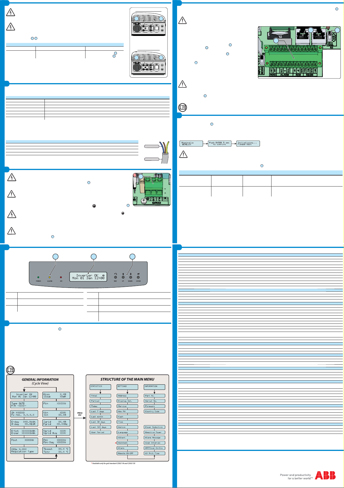
/('VDQG%877216, in various combinations, can be used to view the status or carry out complex actions that are described more fully in the manual.
080706
/('
32:(5
*5((1 On if the inverter is working correctly. Flashes when
FKHFNLQJWKHJULGRULIWKHUHLVLQVXI¿FLHQWVXQOLJKW
ESC It is used to access the main menu, to go back to the previous menu
or to go back to the previous digit to be edited
/('
$/$50
<(//2: The inverter has detected an anomaly. The anomaly
is shown on the display. UP It is used to scroll up the menu options or to shift the numerical scale
in ascending order
/('
GFI 5('Ground fault on the DC side of the PV generator.The
error is shown on the display. '2:1 It is used to scroll down the menu options or to shift the numerical
scale in descending order
(17(5 ,WFDQEHXVHGWRFRQ¿UPDQDFWLRQWRDFFHVVWKHVXEPHQXIRUWKH
selected option (indicated by the > symbol) or to switch to the next
digit to be edited
$%%LQYHUWHUVDUHHTXLSSHGZLWKDJUDSKLF'LVSOD\
07
, consisting of 2 lines of 16 characters each, which can be used to:
- Display the operating state of the inverter and the statistical data
- Display the service messages for the operator
- Display the alarm and fault messages for the operator
- Changing the settings of the inverter
During the normal operation of the inverter the display cycles through the *(1(5$/,1)250$7,21. This information relates to the input and output parame-
WHUVDQGWKHLQYHUWHULGHQWL¿FDWLRQSDUDPHWHUV%\SUHVVLQJ(17(5 it is possible to lock scrolling on a screen to be constantly displayed.
Press ESC to access the three main menus, which have the following functions:
-67$7,67,&6 Displays the statistics
-6(77,1*6 Modify the settings of the inverter
-,1)2 View service messages for the operator
5HIHUWRWKHPDQXDOIRUGHWDLOVUHJDUGLQJXVHDQGIXQFWLRQVDYDLODEOHLQWKHPHQX
39,7/287' 39,7/287' 39,7/287'
Input
Absolute Maximum Input Voltage (V
max,abs
)600 V
Input Activation Voltage (V
start
)200 V (adj. 120...350 V)
Input Operating Range (V
dcmin
...V
dcmax
)0.7 x Vstart...580 V
Rated DC Input Power (P
dcr
) 3120 Wp 3750 Wp 4375 Wp
Number of Independent MPPTs 2
Maximum Input Power for each MPPT (P
MPPT max
) 2000 W 3000 W 3000 W
MPPT Input DC Voltage Range (V
MPPT min
,f ... V
MPPT max
,f) at P
acr
160...530 V 120...530 V 140...530 V
Maximum DC Input Current (I
dc max
) / for each MPPT (I
MPPT max
) 20.0 A / 10.0 A 32.0 A / 16.0 A 32.0 A / 16.0 A
Maximum Input Short Circuit Current for each MPPT 12.5 A 20.0 A 20.0 A
Maximum Backfeed current (from AC to DC side) Negligible
Number of DC Inputs Pairs for each MPPT 112 for MPPT1 and 1 for MPPT2
DC Connection Type Tool Free PV Connector WM / MC4
Input protection
Reverse Polarity Protection Yes, from limited current source
Input Overvoltage Protection for each MPPT - Varistor 2
Photovoltaic Array Isolation Control According to local standard
DC Switch Rating (-S Version) Max. 25.0 A/ 600 V
Output
AC Grid Connection Type Monophase
Rated AC Power (P
acr
) 3000 W 3600 W 4200 W
Maximum AC Output Power (P
ac max
)3300 W
(1)
4000 W
(2)
4600 W
(3)
Rated AC Grid Voltage (V
acr
)230 V
AC Voltage Range 180...264 Vac
(4)
Maximum AC Output Current (I
ac max
) 14.5 A 17.2 A
(5)
20.0 A
Inrush Current Negligible
Maximum Output Fault Current <25 A rms (100mS)
5DWHG2XWSXW)UHTXHQF\I
r
)+]+]
2XWSXW)UHTXHQF\5DQJHI
min
...f
max
)+]
(6)
Nominal Power Factor (Cosphi
acr
) >0.995 adj. ± 0.9 with Pacr=
3.0 kW >0.995 adj. ± 0.9 with Pacr=
3.6 kW >0.995 adj. ± 0.9 with Pacr=
4.2 kW
Total Harmonic Distortion of Current < 3.5%
AC Connection Type Screw terminal block
Output protection
Anti-Islanding Protection According to local standard
Maximum AC Overcurrent Protection 16.0 A 19.0 A 22.0 A
Output Overvoltage Protection - Varistor 2 (L - N / L- PE)
Operating performance
0D[LPXP(I¿FLHQF\Ș
max
)96.8%
:HLJKWHG(I¿FLHQF\(852&(& 96% / -
Power Input Treshold 10.0 W
Stand-by Consumption < 8.0 W
Communication
Wired Local Monitoring PVI-USB-RS232_485 (opt.), PVI-DESKTOP (opt.)
Remote Monitoring PVI-AEC-EVO (opt.), VSN700 Data Logger (opt.)
Wireless Local Monitoring PVI-DESKTOP (opt.) with PVI-RADIOMODULE (opt.)
User Interface LCD Display with 16 characters x 2 line
Environmental
Ambient Temperature Range -25...+60°C /-13...140°F with
derating above 50°C/122°F -25...+60°C /-13...140°F with
derating above 55°C/131°F -25...+60°C /-13...140°F with
derating above 50°C/122°F
Storage Temperature -40...80°C (-40...+176°F)
Relative Humidity 0...100% condensing
(QYLURQPHQWDOSROOXWLRQFODVVL¿FDWLRQIRUH[WHUQDOHQYLURQPHQW 3
Noise Emission < 50 dB(A) @ 1 m
Maximum Operating Altitude without Derating 2000 m / 6560 ft
Environmental Category External
Physical
Environmental Protection Rating IP 65
Cooling Natural
Dimension (H x W x D) 618 x 325 x 222 mm / 24.3 x 12.8 x 8.7 inch
Weight 17.5 kg / 38.6 lb
Mounting System Wall bracket
Overvoltage Category in accordance with IEC 62109-1 II (DC input) III (AC output)
Safety
Isolation Level Transformerless (TL)
Safety Class I
Marking CE +]RQO\
1. Limited to 3000 W for Germany
2. Limited to 3600 W for Germany
3. Limited to 4200 W for Germany
7KH$&YROWDJHUDQJHPD\YDU\GHSHQGLQJRQVSHFL¿FFRXQWU\JULGVWDQGDUG
5. Restricted to 16 A(up to the maximum output power of 3680 W) for the
standard UK G83/1.
7KH)UHTXHQF\UDQJHPD\YDU\GHSHQGLQJRQVSHFL¿FFRXQWU\JULGVWDQGDUG
5HPDUN)HDWXUHVQRWVSHFL¿FDOO\OLVWHGLQWKHSUHVHQWGDWDVKHHW
are not included in the product

This manual suits for next models

5

Other ABB Inverter manuals

ABB UNO-DM-6.0-TL-PLUS-US User manual

ABB

ABB UNO-DM-6.0-TL-PLUS-US User manual

ABB PVS300 User manual

ABB

ABB PVS300 User manual

ABB UNO-DM-1.2-TL-PLUS-Q User manual

ABB

ABB UNO-DM-1.2-TL-PLUS-Q User manual

ABB PVI-3.0-TL-OUTD-W User manual

ABB

ABB PVI-3.0-TL-OUTD-W User manual

ABB PVS-100-TL-B-SY2 User manual

ABB

ABB PVS-100-TL-B-SY2 User manual

ABB UNO-2.0-TL-OUTD User manual

ABB

ABB UNO-2.0-TL-OUTD User manual

ABB PVS980-58 Guide

ABB

ABB PVS980-58 Guide

ABB UNO-DM-2.0-TL-PLUS User manual

ABB

ABB UNO-DM-2.0-TL-PLUS User manual

ABB UNO-DM-TL-PLUS-US User manual

ABB

ABB UNO-DM-TL-PLUS-US User manual

ABB TRIO-50.0 User manual

ABB

ABB TRIO-50.0 User manual

ABB ACS880-07CLC User manual

ABB

ABB ACS880-07CLC User manual

ABB PVI-3.0-TL-OUTD-S-US User manual

ABB

ABB PVI-3.0-TL-OUTD-S-US User manual

ABB PVI-8.0-TL-OUTD User manual

ABB

ABB PVI-8.0-TL-OUTD User manual

ABB PVI-5000-OUTD-US User manual

ABB

ABB PVI-5000-OUTD-US User manual

ABB REACT-3.6-TL User manual

ABB

ABB REACT-3.6-TL User manual

ABB PVS980-MWS User manual

ABB

ABB PVS980-MWS User manual

ABB PVI-3.0-OUTD-S-US-A User manual

ABB

ABB PVI-3.0-OUTD-S-US-A User manual

ABB REACT-BATT-AP1 User manual

ABB

ABB REACT-BATT-AP1 User manual

ABB PVS-100 Series User manual

ABB

ABB PVS-100 Series User manual

ABB UNO-DM-1.2-TL-PLUS User manual

ABB

ABB UNO-DM-1.2-TL-PLUS User manual

ABB UNO-DM-6.0-TL-PLUS User manual

ABB

ABB UNO-DM-6.0-TL-PLUS User manual

ABB PVI-GSM/GPRS User manual

ABB

ABB PVI-GSM/GPRS User manual

ABB UNV-F User manual

ABB

ABB UNV-F User manual

ABB UNO-DM-3.3-TL-PLUS User manual

ABB

ABB UNO-DM-3.3-TL-PLUS User manual

Popular Inverter manuals by other brands

Hobart 6824-1 Operation and maintenance manual

Hobart

Hobart 6824-1 Operation and maintenance manual

Hoymiles HMS-700-2T Quick installation guide

Hoymiles

Hoymiles HMS-700-2T Quick installation guide

enphase Ensemble Technical brief

enphase

enphase Ensemble Technical brief

Viessmann Vitosol-F XL manual

Viessmann

Viessmann Vitosol-F XL manual

GE HOME NERATOR SYSTEM 18000 WATT Installation and start-up manual

GE

GE HOME NERATOR SYSTEM 18000 WATT Installation and start-up manual

Kohler 10ERG Operation manual

Kohler

Kohler 10ERG Operation manual

Vu Phong S400VA user manual

Vu Phong

Vu Phong S400VA user manual

Hitecsa ACVIBA HE Series Installation, operation & maintenance manual

Hitecsa

Hitecsa ACVIBA HE Series Installation, operation & maintenance manual

INVT Goodrive10 Series Operation manual

INVT

INVT Goodrive10 Series Operation manual

Northern Tool 8kW owner's manual

Northern Tool

Northern Tool 8kW owner's manual

ITW GSE 4400 manual

ITW GSE

ITW GSE 4400 manual

Exide integra 700 User's manual & warranty card

Exide

Exide integra 700 User's manual & warranty card

Zeversolar Evershine TLC5000 Quick installation guide

Zeversolar

Zeversolar Evershine TLC5000 Quick installation guide

Growcol GHyper 3000 user manual

Growcol

Growcol GHyper 3000 user manual

Sterling Power Pro Power SB quick guide

Sterling Power

Sterling Power Pro Power SB quick guide

Grundfos RSI Installation and operating instructions

Grundfos

Grundfos RSI Installation and operating instructions

FAR 3090 Installation instruction

FAR

FAR 3090 Installation instruction

Resol DeltaSol AL E Manual for the specialised craftsman

Resol

Resol DeltaSol AL E Manual for the specialised craftsman

manuals.online logo
manuals.online logoBrands
  • About & Mission
  • Contact us
  • Privacy Policy
  • Terms and Conditions

Copyright 2025 Manuals.Online. All Rights Reserved.