SkyAzúl Greer MG514 Use and care manual

Greer – MG514
Retrofit
Installation, Calibration, and Service Manual


Greer – MG514 Retrofit Installation, Calibration, and Service Manual
SkyAzúl, Equipment Solutions www.skyazul.com 301-371-6126
NOTICE
SkyAzúl makes no warranty of any kind with regard to this material, including, but not limited to, the
implied warranties of merchantability and/or its fitness for a particular purpose.
SkyAzúl will not be liable for errors contained in this manual or for incidental or consequential
damages in connection with the furnishing, performance, or use of this manual. This document
contains proprietary information, which is protected by copyright, and all rights are reserved.
No part of this document may be photocopied, reproduced, or translated to another language without
the prior written consent of SkyAzúl.
SkyAzúl reserves proprietary rights to all drawings, photos and the data contained therein. The
drawings, photos and data are confidential and cannot be used or reproduced without the written
consent of SkyAzúl. The drawings and/or photos are subject to technical modification without prior
notice.
All information in this document is subject to change without notice.
SkyAzúl, Inc.
16 Walnut Street
Middletown, MD 21769
Fax 301-371-0029
info@skyazul.com


2
TABLE OF CONTENTS
1.0 Introduction ................................................................................................................................. 5
1.1 System Information.................................................................................................................. 5
1.2 Upgrade Parts ......................................................................................................................... 6
1.2.1 A450862 Computer Assembly .......................................................................................... 6
1.2.2 A450300 RCI 514 Display Module .................................................................................... 6
1.2.3 A240690 Reeling Drum .................................................................................................... 6
1.3 Computer Wiring...................................................................................................................... 7
1.4 Units with Swing Switches ....................................................................................................... 9
1.5 Removal and Installation ....................................................................................................... 10
2.0 Calibration................................................................................................................................. 12
2.1 Required Tools ...................................................................................................................... 12
2.2 Number Conversion............................................................................................................... 12
2.3 The MicroGuard 514 Display ................................................................................................. 13
2.3.1 Command Entry.............................................................................................................. 13
2.3.2 Number Entry ................................................................................................................. 13
2.4 Preliminary Checks and Measurements................................................................................. 15
2.4.1 Boom Pivot Dimensions.................................................................................................. 15
2.4.2 Winch Dimensions.......................................................................................................... 16
2.4.3 Boom Cylinder Dimensions............................................................................................. 17
2.4.4 Span Dimensions ........................................................................................................... 17
2.4.5 Auxiliary Head Dimensions............................................................................................. 18
2.4.6 Stowed Jib Dimensions .................................................................................................. 18
2.5 Installation Checks................................................................................................................. 19
2.5.1 Attaching the Anti-Two-Block (ATB) Cable and Extension Sensor Zero.......................... 19
2.6 Entering Calibration Data....................................................................................................... 20
2.6.1 Menu 00 –Error Codes .................................................................................................. 21
2.6.2 Menu 01 –Crane Data ................................................................................................... 22
2.6.3 Menu 02 - Dimensions.................................................................................................... 23
2.6.4 Menu 03 - Zero Sensors ................................................................................................. 24
2.6.5 Menu 04 - Span Sensor.................................................................................................. 25
2.6.5.1 Angle Span.............................................................................................................. 26
2.6.6 Menu 05 - Swing Potentiometer (If Equipped) ................................................................ 27
SkyAzúl, Equipment Solutions
www.skyazul.com
301-371-6126

3
2.6.7 Menu 06 - Pressure ........................................................................................................ 28
2.6.8 Menu 07 - Radius/Moment.............................................................................................. 31
2.6.9 Menu 08 - Boom Deflection ............................................................................................ 37
2.6.10 Menu 09 - Head Angle.................................................................................................... 39
2.6.11 Menu 10 - Erected Attachments ..................................................................................... 40
2.6.12 Menu 11 - Enable Winches............................................................................................. 41
2.6.13 Menu 12 - Digital Inputs.................................................................................................. 42
2.6.14 Menu 13 - Pressure Monitor ........................................................................................... 43
2.6.15 APPENDIX A –Measurement Records .......................................................................... 44
3.0 Troubleshooting ........................................................................................................................ 48
3.1 Overview & Preparation......................................................................................................... 48
3.2 System Self-Test ................................................................................................................... 49
3.2.1 Display Console Problems.............................................................................................. 50
3.3 Fault Reporting and Fault Codes ........................................................................................... 51
3.3.1 Group “A” Fault Codes.................................................................................................... 52
3.3.2 Group “B” Fault Codes.................................................................................................... 53
3.3.3 Group “C” Fault Codes ................................................................................................... 54
3.3.4 Group “D” Fault Codes ................................................................................................... 55
3.3.5 “No Fault Code” Problems .............................................................................................. 56
3.3.5.1 Anti-Two-Block Alarm (ATB) .................................................................................... 56
3.3.5.2 Displayed Load or Radius Errors ............................................................................. 57
3.4 Computer Unit Overview........................................................................................................ 59
3.4.1 Computer Unit Layout..................................................................................................... 59
3.4.2 Internal Status Indicators ................................................................................................ 60
3.4.3 Pressure Sensors ........................................................................................................... 60
3.4.4 Replacing the Computer Unit Computer Removal .......................................................... 61
3.5 Display Console Overview ..................................................................................................... 62
3.5.1 Unresponsive Buttons..................................................................................................... 62
3.5.2 Connectors ..................................................................................................................... 62
3.5.3 Horn ............................................................................................................................... 62
3.5.4 Moisture.......................................................................................................................... 62
3.5.5 Replacing the Display Console ....................................................................................... 63
3.6 Remote Bar Graph Overview................................................................................................. 64
3.6.1 Checking the Remote Bar Graph.................................................................................... 64
SkyAzúl, Equipment Solutions
www.skyazul.com
301-371-6126

4
3.6.2 LEDs .............................................................................................................................. 64
3.6.3 Brightness Control .......................................................................................................... 64
3.6.4 Cable and Connector...................................................................................................... 65
3.6.5 Moisture.......................................................................................................................... 65
3.6.6 Remote Bar Graph Replacement.................................................................................... 65
3.7 Reeling Drum Overview......................................................................................................... 66
3.7.1 Checking the Reeling Drum Cable Layering ................................................................... 67
3.7.2 Checking the Extension Sensor Drive Voltage................................................................ 68
3.7.3 Checking the Boom Extension Sensor Voltage............................................................... 68
3.7.4 Physical Zero.................................................................................................................. 69
3.7.5 Checking the Angle Sensor Pendulum ........................................................................... 70
3.7.6 Checking the Angle Sensor Drive Voltage ...................................................................... 71
3.7.7 Checking the Angle Sensor Voltage ............................................................................... 71
3.7.8 Reeling Drum Replaceable Parts.................................................................................... 71
3.7.8.1 Reeling Drum Cable ................................................................................................ 72
3.7.8.2 Slip-Ring Assembly ................................................................................................. 74
3.7.8.3 Sensor Baseplate Assembly.................................................................................... 75
3.7.8.4 Signal Cable Assembly............................................................................................ 77
3.8 Anti Two-Block Function Overview ........................................................................................ 79
3.8.1 Checking the Reeling Drum Cable.................................................................................. 80
3.8.2 Checking the Anti-Two-Block Circuit............................................................................... 80
3.9 Swing Sensor Overview......................................................................................................... 81
3.9.1 Checking the Swing Sensor Drive Voltage...................................................................... 82
3.9.2 Checking the Swing Sensor Output Voltage ................................................................... 82
3.9.3 Checking the Swing Sensor Resistance ......................................................................... 82
3.9.4 Swing Sensor Setup and Checks.................................................................................... 82
4.0 Revision History ........................................................................................................................ 85
SkyAzúl, Equipment Solutions
www.skyazul.com
301-371-6126

5
1.0 Introduction
The MicroGuard MG514 replaces the previous Link Belt MG404, 414, and 434 systems currently in
use. This chapter will cover information necessary for installing the MicroGuard 514 system.
Please read the Operator’s Manual before operating the system. The system installer must be
knowledgeable in safety guidelines, crane capacity information, and the crane manufacturer’s
specifications.
For questions about Installation, please contact Technical Support:
Greer Company Service:
Jenks, OK
Telephone: (918) 298-8300
FAX: (918) 298-8301
1.1 System Information
When installing the new computer and display system, Greer Company recommends the existing
rectangular shaped reeling drum be replaced with our current production reeling drum, A240690. The
rectangular shaped reeling drum has been classed obsolete. There is no longer field support for this
product.
Upgrading the reeling drum will ensure you have both field support and parts support in the future. The
A240690 Reeling Drum is equipped with the necessary parts to be a direct replacement for the
obsolete part.
The new computer uses Flash RAM technology for loading the Duty Files. If known at the time of
purchase, the proper Duty File will be loaded on your computer before installation.
If you are unfamiliar with preparing the computer for use, kit K758746 is available from Greer Company.
The kit contains a programming cable and a CD with software, drivers, and the “Greer Mini Loader”
program.
SkyAzúl, Equipment Solutions
www.skyazul.com
301-371-6126
6
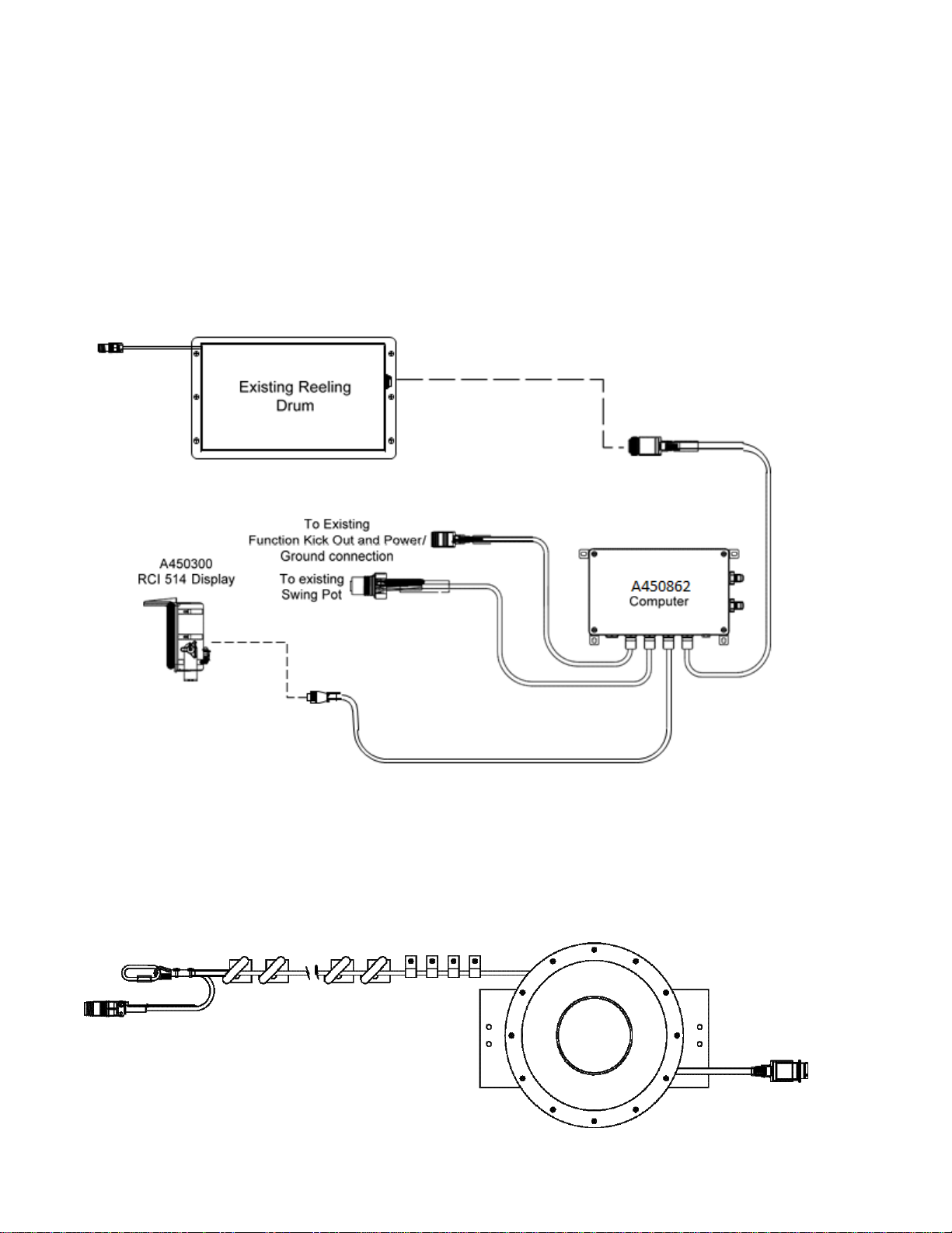
1.2 Upgrade Parts
1.2.1 A450862 Computer Assembly
The computer assembly includes a wiring harness adapted to integrate with the existing Link Belt crane
wiring harness. Refer to the installation drawing below.
1.2.2 A450300 RCI 514 Display Module
This display module is designed specifically for upgrading Link Belt cranes and operates with Link Belt-
style menus.
1.2.3 A240690 Reeling Drum
If you replace the existing reeling drum with A240690, you must also replace the guides for the Anti-
Two-Block cabling. The guides support the level wind system of the reeling drum. The part number for
the guides is K056005. This kit contains a brochure, W056005, explaining how to install the guides and
obtain the best reeling drum performance.
SkyAzúl, Equipment Solutions
www.skyazul.com
301-371-6126

7
1.3 Computer Wiring
The RCI 514 system wiring is based on the original wiring done by the factory. Greer Company cannot
assume responsibility for color codes used on wiring done at the time of origin.
We have identified the wiring inside and outside of our computer module to assist in the wiring
connections. It is the responsibility of the installer to identify the proper wire identifications and routings
on the crane for connecting to the MG514 computer. Please reference the wiring diagram below for
wiring designations
NOTICE: The white (WHT) wire on BLD7 is not required if the jumper wire between BLD3 and BLD7 is
present.
SkyAzúl, Equipment Solutions
www.skyazul.com
301-371-6126

8
S450612
A450862
Work Instruction
Connection
Connection
JP3-1Battery 0V
BLD 1 Battery -VE
Connect to Frame Ground
System Power JP3-2
BLD 2 Battery +VE
Connect to Crane Power 12V - 36V (Fused at
10 Amp power source)
JP 5-1 Function Kick
Out (FKO) Feed
BLD 7 FKO Feed
Incoming Crane Power for Function Kickout
JP 5-2 Solenoid
Output
BLD 8 Solenoid
Output
Power to Function Kick Out Solenoids on
Crane
JP 5-3 Solenoid
Output
BLD 9 Boom Mode
Power to Boom Mode
Connection
Connection
Work Instructions
JP 12-1 (Data "A")
BLD 38 (Data "A")
Display Communication connection
JP 12-2 (Data "B")
BLD 39 (Data "B")
Display Communication connection
JP 12-3 Reset
BLD 40 Reset
Reset line…..Usually Blue
JP 12-4 Display
Power
BLD 41 Power
12V Power for Display
JP 12-5
BLD 42
Display Ground Wire
Connection
Connection
Work Instructions
JP9-1
BLD 26
Digital Input (12V)
JP9-2
BLD 27
Digital Input (12V)
JP9-3
BLD 28
Digital Input (12V)
JP9-4
BLD 29
Digital Input (12V)
BLD30
12V Power Supply
Connection
Connection
Work Instructions
JP11-1
BLD 34
Drive Voltage for Swing Pot
JP 11-2
BLD 35
Ground Signal for Swing Pot
JP 11-3
BLD 36
Communication Connection
JP 11-4
BLD 37
Communication Connection
Connection
Connection
Work Instructions
JP8-1
BLD 20
Monitored Voltage Signal Anti 2 Block
JP8-2
BLD 21
Analog Signal from Ext. to Computer
JP8-3
BLD 22
Analog Signal from Angle to Computer
JP8-4
BLD 23
Monitored Voltage Signal Anti 2 Block
JP8-5
BLD 24
Protected 5 Volts (Drive Voltage)
JP8-6
BLD 25
Internal Ground (Drive Voltage)
SkyAzúl, Equipment Solutions
www.skyazul.com
301-371-6126

9
1.4 Units with Swing Switches
Some older units in the field may use swing switches instead of swing potentiometers, use the
appropriate work area schematic.
Description
Connection
A450763
Work Instruction
Rear
BLD 26
DIN 0
Over Rear
Side
BLD 27
DIN 1
Over Side Chart
Front
BLD 28
DIN 2
Over Front Chart
Between Tires
BLD 29
DIN 3
Between Tires Chart
Power
BLD 30
VP+
Switched Power
BLD 26
BLD 27
BLD 30
BLD 29
BLD 26
BLD 27
BLD 30
DIN 0
DIN 1
+VP
NO
NC
CBLD 28
BLD 27
BLD 30
DIN 2
DIN 1
+VP
NO
NC
C
DIN 3
DIN 0
DIN 1
NO
NC
CNO
NC
C
+VP
BLD 29
BLD 28
BLD 27
BLD 30
DIN 3
DIN 2
DIN 1
NO
NC
CNO
NC
C
+VP
OVER REAR / 360 OVER FRONT / 360
INLINE / OVER REAR / 360 INLINE / FRONT / 360
/
/
SkyAzúl, Equipment Solutions
www.skyazul.com
301-371-6126
10
1.5 Removal and Installation
1. Place the crane in rigging mode and raise the boom. This will allow access to the hose fittings
and wiring harness connections.
NOTE: Leave the Power and FKO cable connected to allow movement of the boom during the removal
and installation process.
2. Disconnect the reeling drum cable.
3. Disconnect the swing sensor.
4. Remove the display.
5. Remove the display cable.
6. Unscrew the four bolts and remove the old computer from its mounting and place computer on
the deck.
NOTE: Do not disconnect the power and FKO cables.
7. The new computer is smaller than the existing one. Mount the new computer using one of the
existing bolt holes. Use the new computer as a template to drill three new mounting holes.
8. Screw in the remaining 3 bolts and ensure the computer is firmly attached.
9. Lower the boom completely. Remove the existing pressure sensors.
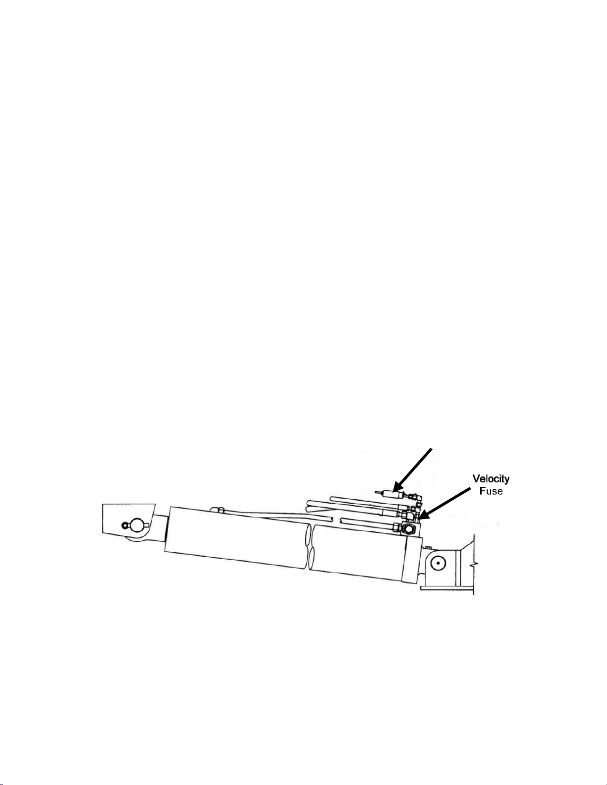
10. Install the new pressure hoses and retain the velocity fuses.
NOTE: Install the velocity fuse In-line with base side pressure sensor. Ensure there is sufficient length
for boom travel without stretching or damaging hoses.
NOTE: Install bleeder fittings at the cylinder. Obtain the fittings from your hose dealer.
WARNING!
Failure to ensure the velocity fuse is correctly installed may cause a dangerous uncontrolled,
downward movement of the boom in the case of hose failure.
11. Connect the new pressure hoses to the new computer.
12. Raise the boom.
13. If using the existing reeling drum, disconnect the reeling drum cable and remove. The new
computer is wired with a new cable and only needs to be attached to the reeling drum. Install
the display.
14. Install the display cable.
SkyAzúl, Equipment Solutions
www.skyazul.com
301-371-6126

11
15. Install the power and FKO cables to the new computer.
16. Slowly elevate the boom to its Maximum Angle to ensure the pressure hoses and electrical
cables are routed properly.
ATTENTION!
It is easy to misroute the pressure hoses and electrical cables. If misrouted, when the boom is
raised the 1st time the hoses/cables can be damaged or destroyed. Use caution.
SkyAzúl, Equipment Solutions
www.skyazul.com
301-371-6126
12
2.0 Calibration
2.1 Required Tools
•1/4” nut driver or T15 Torx driver
•Digital or bubble level calibrated and accurate to 0.1° at level
•Digital volt/Ohm Meter capable of measurements to three decimal places
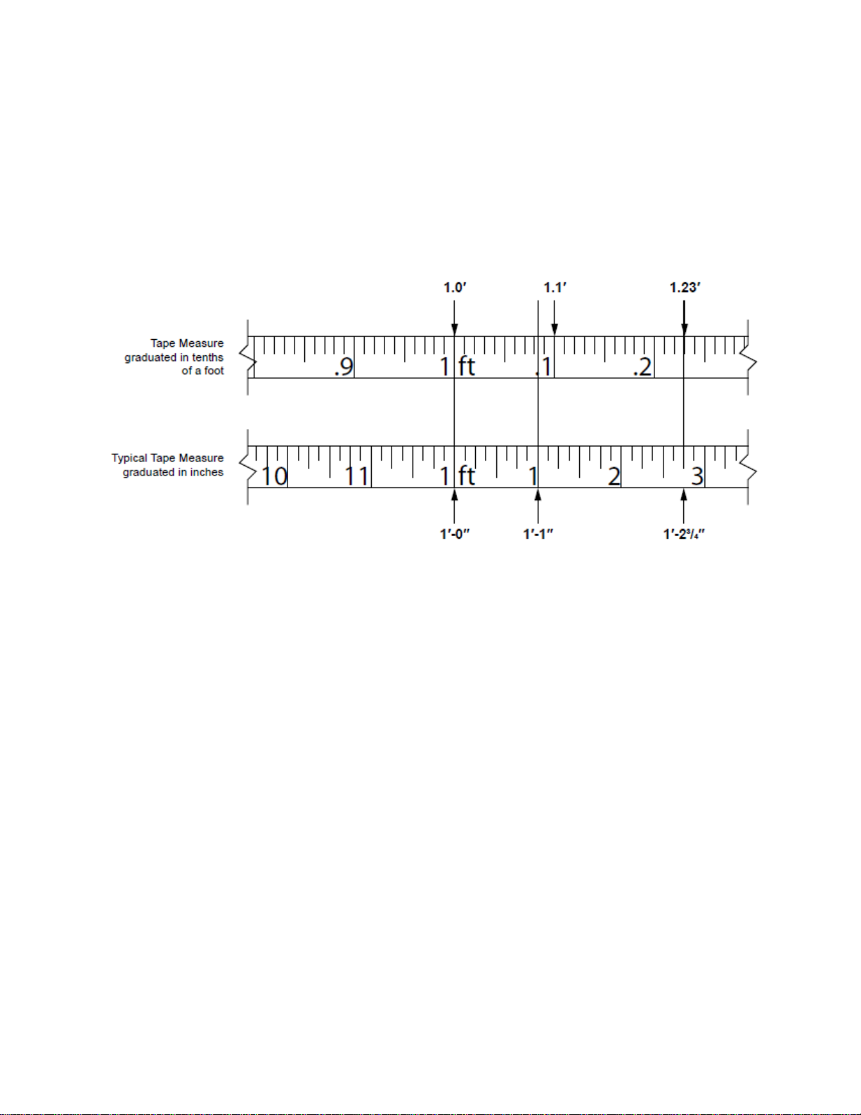
•100 foot measuring tape: fiber type graduated in tenths of feet
NOTE: The computer calculates measurements in feet and tenths of a foot, so using the correct tape
measure is essential for entering the measurements.
2.2 Number Conversion
If a standard tape measure is being used, convert the measurement into feet and tenths of a foot. For
example: a distance of 35’–6” would be entered into the system as 35.5 feet. Whole inches can be
easily converted by dividing by 12 (6/12=.5). Fractions of an inch are converted by dividing the
numerator by the denominator.
For example: 1/4 inches would be entered as .25 (1/4=.25). Conversion of whole inches and fractions
of an inch (for example 6-1/4”) are converted by first converting the fraction to a decimal and then
dividing by 12. In this case 6-1/4” is converted to 6.25 and then divided by 12 which equals 0.520. Refer
to the Fraction to Decimal Conversion Chart.
When entering weights, convert the number by moving the decimal three places to the left. For
example: enter 1,400 pounds as 1.4, enter 300 pounds as .300.
SkyAzúl, Equipment Solutions
www.skyazul.com
301-371-6126
13
2.3 The MicroGuard 514 Display
2.3.1 Command Entry
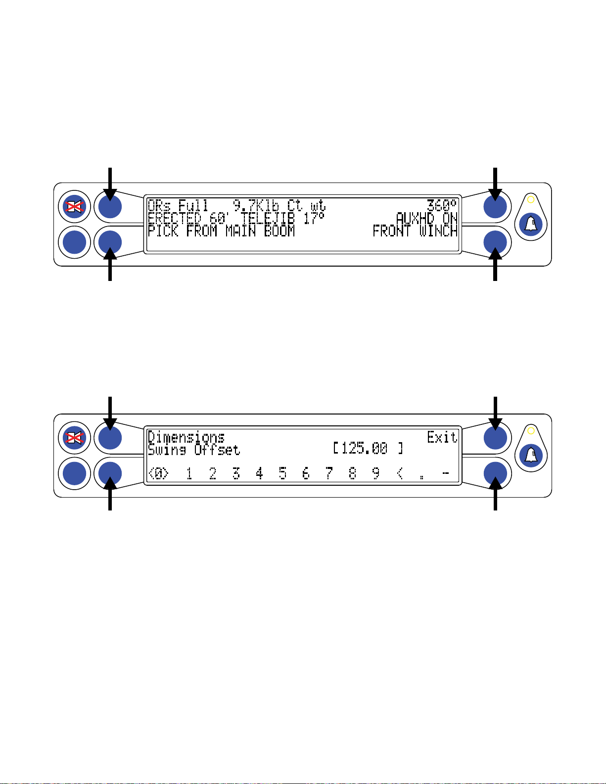
The A, B, C, and Dbuttons are used most for the procedures described in this document and their
function will vary depending on the routine being performed. Commands for each routine will show in
the information window as text adjacent to the buttons. Follow the directions for each routine carefully.
2.3.2 Number Entry
The display does not have a numerical keypad so when numbers are required, the display will change
to enable number entry.
Buttons Band Dare used to scroll left and right. The “cursor” will appear as flashing < > brackets on
either side of the number. Button Ais used to enter the number. Button Cis used to exit the number
entry subroutine.
As each number is selected, press Button Ato enter it into the system. The number will then appear in
the [ ] brackets. Up to five numbers may be entered. When entering a negative value, enter the minus
sign first, then enter the numbers and decimal. When all numbers are correct, press the Cbutton to
calibrate the complete number.
Example: To enter the value “-2.98”:
1. Press button Bor Duntil the number “2” is selected (indicated by flashing < > brackets) and
then press button A to enter the number.
TEST
SET
A
B
C
D
TEST
SET
A
B
C
D
SkyAzúl, Equipment Solutions
www.skyazul.com
301-371-6126

14
NOTE: If a number is entered incorrectly, select the backspace “<” and press button A.
2. Select the decimal “.” then press button A.
3. Repeat steps 1 and 2, to enter the numbers “9” and “8”.
4. After the numbers are entered, press button Bor Duntil the minus sign “-” is selected and then
press button A.
5. If the value is correct, press button Cto exit.
SkyAzúl, Equipment Solutions
www.skyazul.com
301-371-6126

15
2.4 Preliminary Checks and Measurements
Record the following measurements and enter them into the system. Validate any data supplied by the
crane manufacturer before calibration begins. Enter all dimensions into the computer in feet and tenths
of a foot.
2.4.1 Boom Pivot Dimensions
The boom must be in a horizontal position (0°) when taking the following measurements. Use the space
provided in Appendix A to record the measurements.
Dimension “L” – The horizontal distance between the center of the boom pivot and the center of the
boom hoist cylinder upper pivot.
Dimension “J” – The vertical distance between the center of the boom pivot and the center of the
boom hoist cylinder upper pivot.
NOTE: If the boom pivot is above the boom hoist cylinder upper pivot the dimension is negative (-).
Dimension “G” – The horizontal distance between the center of the boom pivot and the center of the
boom hoist cylinder lower pivot.
Dimension “H” – The vertical distance between the center of the boom pivot and the center of the
boom hoist cylinder lower pivot.
USE THE SPACE PROVIDED IN APPENDIX A TO RECORD THE MEASUREMENTS.
SkyAzúl, Equipment Solutions
www.skyazul.com
301-371-6126

16
2.4.2 Winch Dimensions
Dimension “G0” and “G1” – The horizontal distance between the center of the front and rear winch,
and the center of the boom pivot.
Dimension “H0” and “H1” – The vertical distance between the center of the front and rear winch and
the center of the boom pivot.
Dimension “J0” and “J1” – The distance between the top sheave and the centerline of the boom
pivot parallel to the horizontal boom plane, (measurement may be identical).
NOTE: If the boom pivot is above the boom hoist cylinder upper pivot as shown in the illustration,
dimension “J” will be negative. It is important to indicate a positive (+) or negative (-) value.
Dimension “L0” and “L1” – The distance between the centerline of the boom pivot perpendicular to
the horizontal boom plane and the center of the bottom sheave (measurement may be identical).
Dimension “N” Swing Offset – The horizontal distance between the center of the boom pivot and the
centerline of rotation.
NOTE: If the centerline of rotation is ahead of the boom pivot as shown in the illustration, the dimension
will be negative. It is important to indicate a positive (+) or negative (-) value.
Dimension “R” Sheave Radius – The distance between the center and the outside edge of the
bottom sheave.
USE THE SPACE PROVIDED IN APPENDIX A TO RECORD THE MEASUREMENT.
SkyAzúl, Equipment Solutions
www.skyazul.com
301-371-6126
17
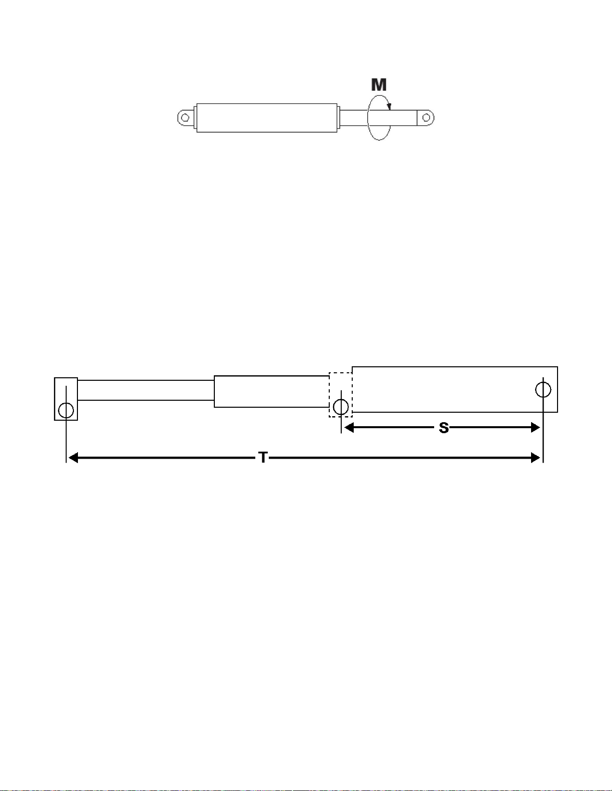
2.4.3 Boom Cylinder Dimensions
Dimension “M” – This is the distance measured around the outside of the cylinder rod, divided by 12.
Then divide this number by 3.14. Record this number for entry into the system.
USE THE SPACE PROVIDED IN APPENDIX A TO RECORD THE MEASUREMENT.
2.4.4 Span Dimensions
WARNING!
SETTING SPANS ON THE CRANE WILL REQUIRE FULL EXTENSION OF THE BOOM. ENSURE
THE CRANE IS SETUP ACCORDING THE MANUFACTURER’S OPERATION MANUAL TO
ENSURE MAXIMUM STABILITY. ENSURE ALL BOOM EXTENSIONS AND LOADS ARE LIFTED
WITHIN THE APPROPRIATE LOAD CHARTS AND LIMITS. FAILURE TO COMPLY WITH THESE
LIMITS MAY RESULT IN SERIOUS INJURY OR DEATH.
Dimension “S” – This is the distance between the center of the boom pivot and the center of the
sheave with the boom fully retracted.
Dimension “T” – This is the dimension between the center of the boom pivot and the center of the
sheave with the boom fully extended.
The span of the boom is calculated by subtracting Dimension “S” from Dimension “T” (T - S = span).
USE THE SPACE PROVIDED IN APPENDIX A TO RECORD THE MEASUREMENT.
SkyAzúl, Equipment Solutions
www.skyazul.com
301-371-6126
Table of contents
Other SkyAzúl Music Mixer manuals


