Skywalker X-8 User manual

Skywalker X8
Assembly manual January 2013
ThisManualWasCreatedbyRayGraubergerwww.raygrauberger.com

Technical Data
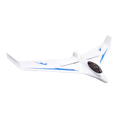
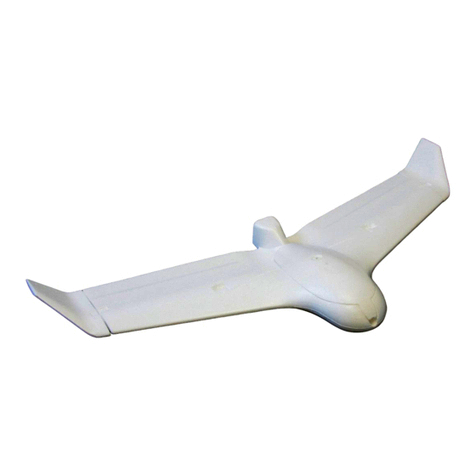
This is the X-8 FPV wing from Skywalker Technology. The BIG FPV wing!
The X-8 has been specifically designed for FPV and UAV, customized for F-Tek stabilizer
systems.
An awesome looking and fantastic flying FPV / UAV platform, molded out of EPO so it's nearly
indestructible!
This model offers a huge amount of under canopy space, excellent glide performance, and fast
low power cruise speeds in the region of 80-90 kph.
The airframe was designed from the outset to take FPV and other video devices, the equipment
bays have been laid out to suit FPV / UAV applications, there is a camera mount in the nose
and there's a forward oblique mount to suit a Gopro. Transporting the airframe is easy, both
the wing panels and the vertical stabs are bolt on affairs.
Nice design points are the molded in wing reflex, removable vertical stabilizers, ventral
launching grips, nose camera bay, canopy retained via strong magnets , molded battery and
FPV trays and 2 through fuselage spars - plus a molded in spar in each wing panel.
It's an impressive airframe that spans 2120mm and has a rather imposing silhouette!
Specs:
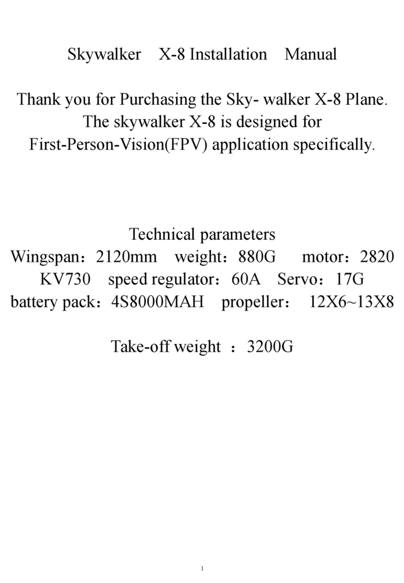
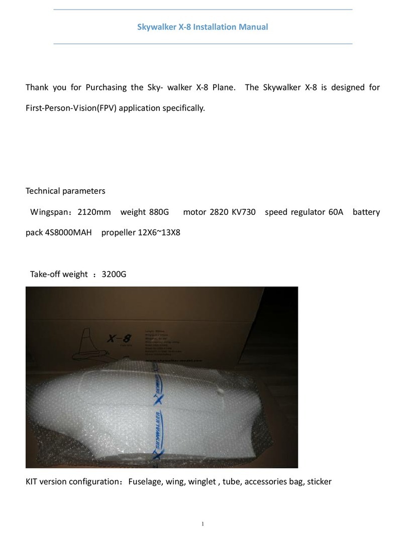
Wingspan: 2120 millimeters
Dry Weight: 880 grams
Take Off Weight: 3200 grams
Motor: 400 – 800 watts dependent on payload
Suggested Motor: 2820 KV730 with 60 amp Esc
Prop: 12 x 6 – 13 x 8 – 13 x 7
Battery: 4s 3000 mA - 6S 5000 mAh
Esc: 40-70 amp
Maximum Weight: 3500 grams
Not Included But Required:
3 or more channel radio system
2 x standard size servos
Propeller and adapter
Brushless out runner
Brushless ESC
Lipo battery
FPV or UAV system

FLIGHT CHARACTERISTICS
When flying your Skywalker X8, please keep in mind these manufacturer guidelines. As everything,
there are exceptions to the rule but these are good points to start with.
Please note that you should, control the Skywalker X8 flight speed within 85 km/H.
If you need a high speed flight you should strengthen wings, otherwise the wings support structure
may fail. Try to keep the Skywalker X8 within 3200 grams. If your build exceeds the 3200 gram
limit, you should strengthen the wings.
If there are technical problems or suggestions, please email or consult your local dealer or distributor
that you purchased your model from.
If you have any questions about this document or anything I can help you with, please email
AFTER BUILD
Skywalker suggests you use brand name quality propeller such as CAM or APC. The design of the Skywalker X8
makes it easy to break down and carry to a field, or store in a smaller space.
CENTER OF GRAVITY
The position of the center of gravity for the Skywalker X8 is 440 millimeters away from the nose, a 5 millimeter
correction either forward or backwards from this point may be needed. The design of the Skywalker X8 puts the
Center of Gravity point and the rear edge of the hand hold slots on the bottom of the model, so measuring is not
needed.
MY CONFIGURATION
Motor: Hacker A40-12S V2
ESC: HACKER X-70 SB PRO
BATTERY: ZIPPY Flightmax 8000 mAh 6S1P 30C
Turnigy nano-tech 8000 mAh 5S 25~50C Lipo Pack
ZIPPY Flightmax 8000 mAh 5S1P 30C
PROPELLER: Graupner CAM Folding Propeller 13 X 7
SPINNER: Aeronaut 2-Blade Black Spinner for Folding Propellers
BLADE STOPPER: Aeronaut Fiberglass Blade Stopper for 2-Blade Spinners
YOKE: Aeronaut Yoke for 2-Blade Spinners

PARTS LIST
QUANTITY DESCRIPTION
1 2PartEPO(expanded polyolefin) SplitFuselage
1 EPOFuselageHatch
2 EPOMainWings
2 EPOMainWingAccessPanels
2 EPOWinglets
1 590.55millimeterFrontCarbonFiberWingTube
1 889millimeterRearCarbonFiberWingTube
1 WoodenOvalMotorMount
4 WoodenMainWingButt‐Plate
2 WoodenUpperWingletButt‐Plate(usedontheWinglets)
2 WoodenLowerWingletButt‐Plate(markedwithaT)(UsedontheMainWings)
2 Standard3WireServoExtensions
2 WireControlArms
2 PressureFitRudderControlHorns
8 NeodymiumMagnets
8 MagnetMountingSurfaces
8 Screws
2 BlackPushrodConnectorScrews
2 PushrodConnectors
2 SqueezeTubesofGlue


Skywalker X8 Assembly Procedure
1. Gluethewingletbutt‐platetothewingletPHOTOS1A,1B,1C,1D
2. Gluethemagneticholddownstructurestogether PHOTOS2A,2B
3. GluethemagneticholddownstructuresintothewingbodyPHOTOS3A,3B,3C
4. GluingtherudderhornsPHOTOS4A,4B
5. Trialfittingtheservoandelevonconfiguration
6. AdvancedwingconfigurationusingDragRudders(seeAppendixA)
7. GluingtheservosinplacePHOTOS7A,7B
8. Mountingthepushrodandpushrodconnector PHOTO8A
9. Gluingthemainwingwingletbutt‐platePHOTOS9A,9B
10. Separatingthecontrolsurfacefromthewing PHOTO10A
11. WingplatebondingwithservoextensionInstallation PHOTOS11A,11B,11C,11D
12. Addingthewingbutt‐platetothemainwings PHOTOS12A,12B,12C,12D
13. Runningtheservoextensionintothemainfuselagebody PHOTOS13A,13B
14. Installingthemotormountintothefuselage PHOTOS14A,14B,14C,14D
15. GluingthefuselagehalvesPHOTOS15A,15B,15C,15D
16. Installingthewingbutt‐plateontothefuselage PHOTOS16A,16B,16C
17. WingletfinalassemblyPHOTO17A
18. AttachingthemotorPHOTOS18A,18B
19. RecessedcameramountPHOTOS19A,19B19C
20. TheSkywalkerX8finalassemblyPHOTOS20A,20B,20C,
21. SkywalkerX8centerofgravityPHOTO21A
22. AssemblyandDisassemblyforTransportation PHOTOS22A,22B,22C,22D,22E
23. FinishedSkywalkerX8PHOTO23A
APPENDIXA–ConvertingStandardElevonToDragRudderConfiguration

Assembly Instructions
1. Gluethewingletbutt‐platetothewinglet
Spreadthesuppliedglueevenlyoverthewingletbottom.Alsospreadthesuppliedglueononesideofthe
woodenbutt‐plate,(makesurethisisNOTthebutt‐platemarkedwitha“T”).Waitapproximately5minutesfor
thegluetodryuntilitisnolongersticky.Dothisforbothpiecesbeforepressingthemtogether,thiswillallow
youtobetteralignthewingletandthebutt‐plate.SeePhotos:1A,1B,1C,and1D.
PHOTO1A
PHOTO1B

PHOTO1C
PHOTO1D
2. Gluethemagnetsandtheholddownstructuretogether
Assemblethehatchmagnetsintothemagnetholdersbyforcingthemintotheprecutholesinthewooden
magnetholders.Makesureyouhave4Northand4SouthPolesets,marktheholdersinawaythatyoudon’t
mixthemup.Doingthisincorrectlywillreversethemagneticforce,thewrongmagneticdirectioncouldcause
anunwantedfailureorhatchlossinflight.Afteryouhaveforcedthemagnetsintoplace,useCyanoacrylateor

(CA)toaffixthemagnetspermanentlyinthewoodenmagnetholders.Justadropwillbeplentytoholdthe
magnets.SeePhotos2Aand2B.
PHOTO2A
PHOTO2B
3. Gluethemagneticholddownstructureintothewingbody
Usingthesuppliedglueapplyliberallytothemagneticholddowns,allowthegluetodryforapproximately5
minutes.Applygluetothewingshatchandfuselagewaitapproximately5minutesforthegluetodry.Afterthe
gluehasdried,payingcloseattentiontotheNorthandSouthpolesofthemagnetsinsertthemintothewing

andfuselage.IfyoupreviouslymarkedtheNorthandSouthpolesofyourmagnetholddownsasmentionedin
Step2,thisassemblyprocedurewillgomucheasier.Afterthegluehassetinboththefuselageandhatchput
thetwopiecestogetherandinspectthefit,makeanyadjustmentsatthistimetoinsurethereisasolidfit
betweenthehatchandthewing.Paycarefulattentiontothespacingbetweenthetwoholddownpartsandthe
wingandhatch.SeePhotos3A,3B,and3C.
PHOTO3A
PHOTO3B

PHOTO3C
4. GluingtheRudderHorns
Spreadjustenoughglueontothewingscontrolsurfacetoaccepttheruddercontrolhorn.Makesureyou
spreadtheglueevenlyandallowittodry.Dothesameforthecontrolhornitself.Afterboththecontrol
surfaceandcontrolhornhavedried,insertthecontrolhornintothepre‐markedholesinthecontrolsurface.
SeePhotos4Aand4B.
PHOTO4A

PHOTO4B
5. Trialfittingtheservoandelevonconfiguration
Thisisthestandardradioset‐upfortheSkywalkerX8.Atthispointyoushouldhaveyourradiosetupforadelta
wing,elevonconfiguration.Ifyouhavenotset‐upyourradioyet,dothisnowbeforecontinuing.Withallof
yourelectronicsturnedonlettheservosself‐centerthemselves.Turnoffyourelectronicsandattachtheservo
hornstoyourservosatarightangletothelongestsurfaceoftheservo.
6. AdvancedWingConfigurationusingDragRudders
Thereisamoreadvancedflyingconfigurationthatrequirescontrolsurfaceandwingmodificationwith
advancedradioset‐updiscussedlaterinthisdocument.SeeAppendixA.
7. Gluingtheservosinplace
Useastandardsizeservooraservothathasmorethan2.5KGofforcefortheSkywalkerX8.Plugintheservo
extensioncablesuppliedwiththekit.Applygluetoonesideoftheservoandalsoapplygluetotheservocut‐
outinthewings.Waitforthegluetodry(approximately5minutes)thenplacetheservointothewing.Place
theservoextensionwireintothepreformedchannelinthewing.SeePhotos7Aand7B.

PHOTO7A
PHOTO7B

8. MountingthePushrodandPushrodConnector
Insertthepushrodintotheuppermostholeintheservoarm.Slidethepushrodconnectorontothepushrodand
attachthepushrodconnectorwithoneofthesuppliedblackscrews.Cutoffanyexcesslengthoffthepushrod.
Thepushrodshouldnotextendmorethan1/8”ofaninchpastthepushrodconnector.SeePhoto8A.
PHOTO8A
9. GluingtheMainWingWingletButt‐Plate
Liberallyapplyasmoothlayerofgluetothewingletbutt‐platethesebutt‐platesaremarkedwitha“T”.Applya
smoothlayerofgluetothemainwingaswell.Allowthegluetodryonboththewingandbutt‐plate(about5
minutes),thenpressthemtogetheraligningthemaccurately.SeePhotos9Aand9B.
PHOTO9A

PHOTO9B
10. SeparatingtheControlsurfacefromtheWing
Useaneworextremelysharpbladetocutthecontrolsurfacesidesfromthewing.YouwillNOTberemoving
thecontrolsurfacecompletely,justallowingittomoveupanddownwiththelongestsideuncut.Itis
recommendedtoleavea1.5millimetergapbetweenthewingandthecontrolsurface.SeePhoto10A.
PHOTO10A

11. WingPlateBondingwithServoExtensionInstallation
Ifyouareusingdragrudders,doNOTdothisstepuntilyouhavereadandcompletedAppendixA.Spreadglue
ontotherecessinthewingwherethewingplatewillsit.MakesureyoudoNOTcovertheWingTubeareawith
glue.Carefullyinserttheservoextensionintothewingpanelcut‐outchannel,makesurethattheservowireis
firmlyinplaceandtheextensionistightfromtheservo.Spreadglueevenlyontothewingplateallowingthe
wingglueandwingplatetodry(about5minutes).Carefullycompressthewingpaneltothewingadjustingfor
fit.Trytomakesurethatthebuttendofthewingplateisevenwiththeendofthewing.SeePhotos11A,11B,
11Cand11D.
PHOTO11A
PHOTO11B

PHOTO11C
PHOTO11D
12. AddingtheWingButt‐PlatetotheMainWing
Applythesuppliedgluetotheinnerwingedge,makesurenottogetanyglueintothewingtubehole.Also
applygluetothebutt‐plate,allowthegluetodryonbothpiecesforabout5minutes.Afterthegluehasdried
insertthewingtubeintoitthewingtubecavitytohelpalignthebutt‐plateforthemostaccuratefit.Nextinsert
thewingtubeintothewingtubeholeinthebutt‐plate,andattachthebutt‐platetothewing.

SeePhotos12A,12B,12C,and12D.
PHOTO12A
PHOTO12B

PHOTO12C
PHOTO12D

13. RunningtheServoExtensionintotheMainFuselageBody
Youwillneedtowidentheslotinthefuselagesothattheplugendoftheservoleadwillfitthroughthehole
afterthefuselagehasbeengluedtogether.SeePhotos13Aand13B.
PHOTO13A
PHOTO13B
14. InstallingtheMotorMountintotheFuselage
Optionallyyoucanattachyourmotortothemotormountbeforegluingitintothefuselage.Ifyoudonotattach
yourmotoratthistimeyoushouldhavenoproblemsmountingthemotorafterfurtherconstruction.See
Photos14A,14B,14C,and14D
Other manuals for X-8
2
Table of contents
Other Skywalker Toy manuals
Popular Toy manuals by other brands

Fisher-Price
Fisher-Price Power Wheels Cruiser M0412 Assembly and owner's manual

ROBBE
ROBBE Edge 540 ARF Assembly and operating instructions

Canon
Canon Creative Park Rabbit Assembly instructions

Mega Bloks
Mega Bloks HALO ONI REAP-X manual
AXM Paper Space Scale Models
AXM Paper Space Scale Models T-38 Assembly manual

Tower Hobbies
Tower Hobbies Turbo Vee 2 Assembly and operation manual

RTS
RTS 3P2 Assembly instructions
Eduard
Eduard ZOOM FE 1057 manual
MD Helicopters
MD Helicopters MD900 with PW206E Flight manual

THUNDER TIGER
THUNDER TIGER 5546 instruction manual

Accucraft trains
Accucraft trains FORNEY LIVE STEAM instruction manual
Kazan Helicopters
Kazan Helicopters Mi-17-1V Flight manual
