SLAGKRAFT SH125 User manual

Artikelnummer 5017 743-R4
English, User manual in original
Copyright
All rights reserved, including the right to reproduce this manual, or parts thereof, in any form, without the
written permission of Cranab AB.
Instruction manual
Horizontal Flail
Model:
SH125 / SH150 / SH170 / SH190 / SH210
SH110-TW / SH150-TW
EuroTest
Certificate
Read through the entire instruction
manual before beginning operation.

2
Products sold after 1995-01-01 are to be CE-marked and in conformance with
the machine directive confirmed by EU.
The manufacturer (importer) holds responsibility for this in the EU and/or EES
area.
EuroTest
Certificate
The EUROTEST mark indicates that the product has been inspected by a
testing station that is independent of the maker of the product, ie, third party
certification.
The EUROTEST mark shows that the product is independently inspected with
regard to common European requirements concerning safety and health related
to this product
To enable a testing station to issue certificates it must fulfil confirmed quality
requirements and its experts inspect the product on the basis of safety and
quality.
SMP Svensk Maskinprovning AB is approved to carry out this third party
certification.
SMP puts its ET-mark on the product when it considers that the product
conforms to EU’s machine directive.

3
C
ONTENTS
1 .................................................................................................................................................................. Introduction 5
Limitation of application.................................................................................. 5
Range of use.................................................................................................. 5
2 .................................................................................................................................................... General description 7
Identification................................................................................................... 7
Direction of rotation ........................................................................................ 8
3 ................................................................................................................................................. Technical description 9
Hydraulic fluids............................................................................................... 9
Filter ............................................................................................................... 9
Hub .............................................................................................................. 10
Safety cover ................................................................................................. 10
Hydraulic motor ............................................................................................ 10
Flail chain..................................................................................................... 10
Chain magazine and chain locks.................................................................. 11
Protective rubber mat................................................................................... 11
Chain curtain................................................................................................ 11
Wear plates and back plate.......................................................................... 11
4 ............................................................................................................................................................. Technical data 12
Standard models .......................................................................................... 12
TW models................................................................................................... 13
5 ..................................................................................................................................................................Safety rules 14
General safety rules ..................................................................................... 14
Safety instructions........................................................................................ 15
Warning decal .............................................................................................. 17
Lifting points................................................................................................. 19
Type plate .................................................................................................... 19
6 .................................................................................................................................................. Connecting to carrier 20
Hoses........................................................................................................... 20
Connecting................................................................................................... 20
7 ................................................................................................................................................ Operating instructions 22
Before starting.............................................................................................. 22
Starting......................................................................................................... 22
Mode of operation ........................................................................................ 22
Hints for light clearing................................................................................... 23
Chain curtain................................................................................................ 23
Flail chain, chain locks and chain magazine ................................................ 23
After operation, general instructions............................................................. 23
Long-term parking / storage..................................................................... 23
Check after long-term parking / storage................................................... 24
8 ......................................................................................................................................................................... Service 25
Electric welding ............................................................................................ 26
Maintenance schedule / Lubrication schedule ............................................. 27
Retightening of bolted joints - Table............................................................. 28

4
Lubrication schedule .................................................................................... 29
Lubricating the drive axle ............................................................................. 30
Cleaning the chain magazine....................................................................... 30
Loading chain into the magazine.................................................................. 31
Changing the protective rubber mat............................................................. 32
Changing the chain curtain .......................................................................... 32
Retightening bolted joints............................................................................. 33
Inspecting slot-and-wedge bolt joints ........................................................... 33
Inspecting bearings ...................................................................................... 34
Inspecting vibration damper under tilt mount ............................................... 34
9 ............................................................................................................................................................ EC Declaration 35

5
1
I
NTRODUCTION
This instruction manual contains information that you should be conversant with
to operate and maintain the horizontal flail in the best way. Study the contents
carefully before putting the flail into operation and carefully follow the
instructions provided. This will ensure the best conditions for long useful life and
interference-free operation.
This instruction manual applies only to Slagkraft’s horizontal flail. Separate
instruction manuals are available for vertical flail, crane, bush clearing machine
type Compact and bush clearing machine with motor package.
Slagkraft reserves the right to freely alter the contents of instructions, directions
and specifications.
The spare parts catalogue is included as a supplement in this instruction
manual and it may contain several model variants than those dealt with in the
manual.
When ordering spare parts the serial number of the horizontal flail should be
stated (see type plate) in addition to the number of the spare part. The reason
for stating the serial number is that design changes may have been made that
could affect the choice of spare parts required.
A machine card accompanies the horizontal flail on delivery indicating the type,
serial number and year of manufacture. If the horizontal flail is part of a
complete bush clearing machine there will also be a machine card for the whole
unit.
Limitation of application
Slagkraft’s flails can be mounted on other carriers than Slagkraft cranes.
Slagkraft’s tilting mounts are therefore available in a variety of designs. It is
essential that the base machine is inspected after fitting to ensure satisfactory
stability. To inspect stability, run the crane boom and horizontal flail to maximum
tilting moment, ie, maximum extended mode at right angles to the direction of
travel for the machine, just above ground level. If the base machine is unstable
it can be balanced with counterweights or stabilising cylinder. Consult Slagkraft
for approval of base machine / combination of flail model.
Range of use
The horizontal flail is designed solely for clearing thickets and bush vegetation
and must be used and maintained in accordance with directions in this
instruction manual. It is especially important that safety rules are adhered to.

6
Study the entire instruction manual before using the flail.
Before mounting it, study the section “connecting to carrier” and section
“Safety rules.”
If the horizontal flail is included in bush clearing machine Compact or
Motor package study also the instruction manual for Compact, Motor
package and Crane respectively.

7
2
G
ENERAL DESCRIPTION
Identification
The horizontal flail consists mainly of safety cover, hub and hydraulic motor and
chain magazine, chain curtain, protective rubber mat, and wear plates.
The type designation of the horizontal flail consists of a number of parts
describing the configuration of the flail. How this designation is built up and what
it means is shown below. The type designation is required in some cases to
enable ordering of the right spare part.
Type designation SH150-80-TW-90 means:
SH150 Working width 150cm
80 Indicates size of hydraulic motor in cc
TW Flail with two open sides, ie, two-way flail.
90 Turning of hub in relation to standard version. This turning is used
mainly on backhoes and excavators. Other turning may also occur.
Saftey cover
Hub and hydraulic
motor, chain magazine
Wear plate
Chain curtain
Back plate with rubber mat
Location of warning decal
Protective rubber mat
Type plate

8
Direction of rotation
Flail have clockwise rotation seen from above. Wear plates, the hood and other
protections are designed for this rotation.
This rotation requires that the pressure line to the hydraulic motor is connected
to the hydraulic motor connection marked “A”.

9
3
T
ECHNICAL DESCRIPTION
The basic principle of the horizontal flail is two horizontally rotating chains.
Bushes and thickets are slashed and the vegetation is disintegrated into chips.
The horizontal flail can be operated using different chain diameters
recommended by Slagkraft, 10 or 13mm. Note that the chain magazine shall
only be filled with one dimension at a time. 10 and 13mm chain may never,
under any circumstances, be mixed in the same magazine.
For clearing with sweeping movement in terrain and for operation back and forth
a special flail is available with two open sides, ie, a two-way flail (type
designation TW). This flail is mainly used on excavators and other off road
machines. For use on roads a standard model is more suitable.
Hydraulic fluids
High requirements are put on the hydraulic fluid, which is the power-transmitting
component in a hydraulic system, to ensure the best possible efficiency and
useful life of the hydraulic system. The fluid, which is primarily intended for use
in equipment for outdoor use, must therefore be suitable for a wide temperature
range. The fluid shall contain additives to counteract foaming, improve film
strength and reduce viscosity temperature dependence.
Temperature range corresponding to the range for kinematic viscosity 1500-
10mm2/s(=cSt) for the standardised hydraulic fluids SHS ISO VG 46.
We recommend fluid with characteristics in conformance with Swedish
Standard for hydraulic fluids SS 15 54 34. This standard includes conventional
hydraulic fluids that have a mineral oil base and also biologically decomposable
hydraulic fluids conforming to the standard and strict environment requirements.
Note. Some suppliers of pumps or components may have other
requirements regarding hydraulic fluids than those noted above. Ensure
therefore that the hydraulic fluid is approved prior to use.
Filter
For maximum useful life and performance the fluid must conform with regard to
cleanliness to ISO-norm 17/13 or better (ISO 4406). A 10µm (absolute) filter is
recommended. The hydraulic system must also be clean in general.

10
Hub
The hub consists of a housing with a spherical bearing in the lower part of the
housing. The lower part of the drive axle between the hydraulic motor and the
chain magazine is carried by the spherical bearing and at the upper end the
bearing is aligned by the outgoing axle of the hydraulic motor. A spline coupling
interconnects the drive axle and hydraulic motor.
Safety cover
The safety cover is made of hardened high-strength steel sheet. The wear
runners are replaceable. The protective rubber mat protects the front edge. The
TW type flail has two protective rubber mats. The cover also has a chain curtain
on the sides not fitted with a protective rubber mat. The chain curtain works as a
flexible extension of the cover and thus reduces the risk of flying stones.
Hydraulic motor
The hydraulic motor is of the bent-axis type with fixed displacement. The
outgoing axle is supported by bearings.
Flail chain
The flail chain is hardened and tempered in conformance with special
requirements for bush clearing. Flail chains are available in two sizes 10 and
13mm. Article number 1046 010 and 1046 002 respectively.
To facilitate identification of flail chain from Slagkraft it is painted blue and
identification marked according to Slagkraft’s instructions. When buying chain,
save the identification marking until the chain is used up.
Use only genuine flail chain to ensure that the guarantees and product
responsibility appertaining to the machine are not impeded

11
Chain magazine and chain locks
The chain magazine has a circular base plate. Two separate chain channels run
on the upper face of the base plate. Chain locks are fitted in the channel
openings to keep the chain in place. The chain magazine is made and heat-
treated to withstand hard wear. The flail chain is fed out manually.
Protective rubber mat
The protective rubber mat is fitted in the opening of the safety cover in the
direction of travel as protection against flying stones and other objects. The
protective rubber mat has several layers of cord.
Chain curtain
The chain curtain consists of chain links. This guard is fitted to the lower part of
the cover as a flexible extension of the cover.
Wear plates and back plate
The purpose of the wear plates is to protect the lower part of the safety cover
against wear. The wear plates are fastened by slot-and-wedge bolts. Wear
plates should be replaced at the latest when they are 6mm around the slot-and-
wedge bolts. If wear plates become unevenly worn they can suitably be moved
over to the opposite side to prolong their useful life. The back plate and the
safety cover are screwed into position and can be replaced as a single unit.
Replace the back plate when there is 2mm metal left at the thinnest position.
The responsibility of Slagkraft (CE and ET-markning) is not available if
there is used other flailchain, chainlock or chainmagazine or other not
genuine parts who direct affect the saftey.

12
4
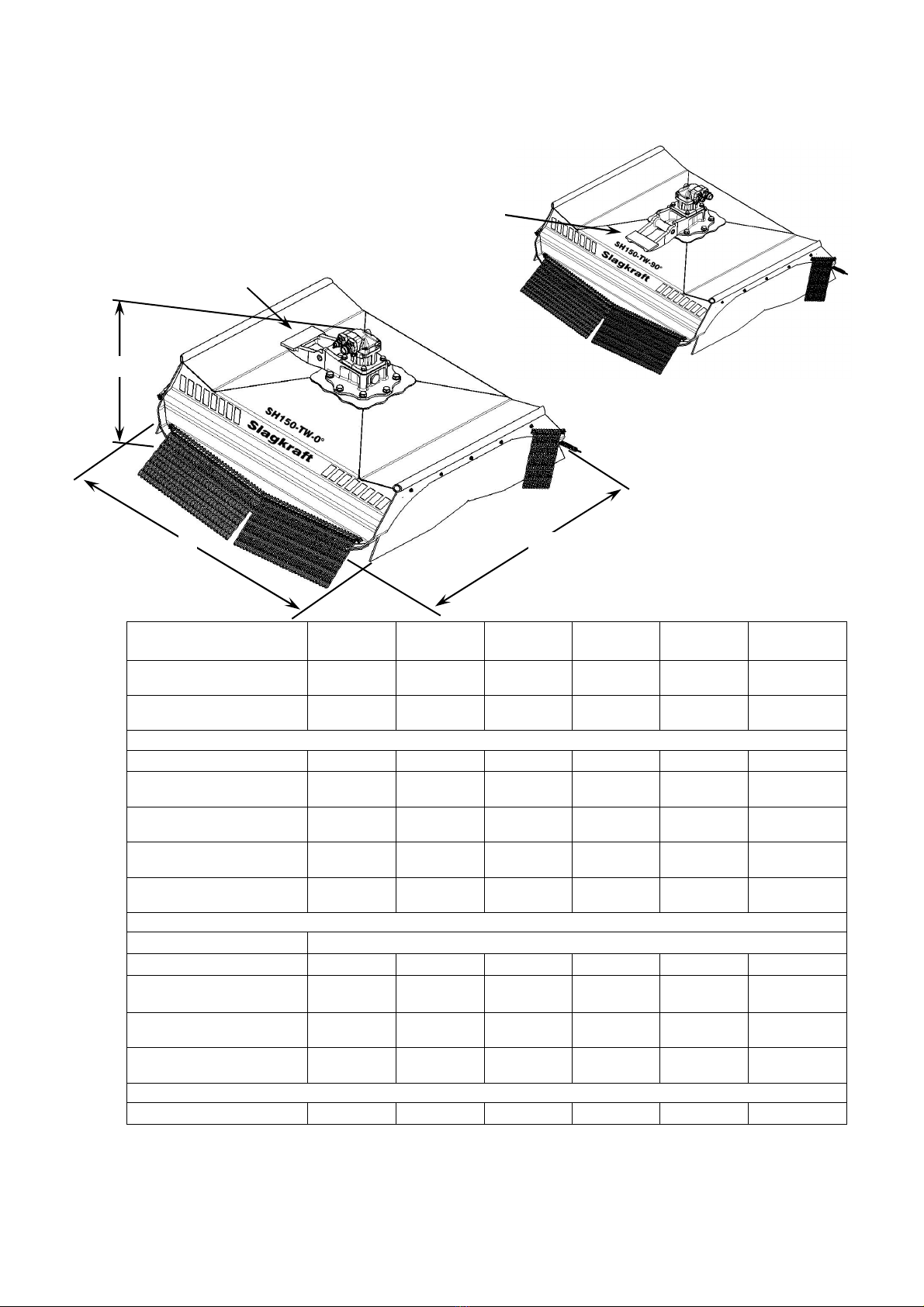
T
ECHNICAL DATA
Standard models
Model SH125 SH150 SH170 SH190 SH210
Working width (mm) 1250
49”
1500
59”
1700
67”
1900
75”
2100
82”
Hydraulic motor (cc) 60
3,66 cu.in
80
4,88 cu.in
90
5,62 cu.in
110
6,71 cu.in
125
7,63 cu.in
Outer dimensions (mm)
Length 1795
70”
1970
77”
2330
92”
2560
100”
2770
109”
Width 1550
61”
1760
69”
2000
78”
2200
86,5”
2390
94”
Height (above superstructure) 910
36”
910
36”
910
36”
920
36”
970
37”
Weight (kg) 525
1155 lbs
595
1309 lbs
665
1463 lbs
750
1650 lbs
780
1716 lbs
Hydraulic pressure Min. 210 bar (3045psi) / Max. 380 bar (5510psi)
Rate of hydraulic flow
Min. (l/min) 100
26,4 gpm
100
26,4 gpm
100
26,4 gpm
100
26,4 gpm
120
31,7 gpm
Preferably (l/min) 120
31,7 gpm
130
34,3 gpm
130
34,3 gpm
130
34,3 gpm
145
38,3 gpm
Max. (l/min) 140
37 gpm
150
39,6 gpm
160
39,6 gpm
160
42,3 gpm
170
45 gpm
Power requirement (kW) 40 (55hp) 45 (60hp) 70 (95hp) 75 (100hp)
80 (110hp)
The unit can be delivered with different tilt mounts.
Due to continual product development we reserve the right to make changes.
H
W
L
13
TW models
Model SH110-40-
TW-0°
SH110-40-
TW-90°
SH150-60-
TW-0°
SH150-60-
TW-90°
°°
°
SH150-80-
TW-0°
SH150-80-
TW-90°
°°
°
Working width (mm) 1100
43”
1100
43”
1500
59”
1500
59”
1500
59”
1500
59”
Hydraulic motor (cc) 40
2,44 cu.in
40
2,44 cu.in
60
3,66 cu.in
60
3,66 cu.in
80
4,88 cu.in
80
4,88 cu.in
Outer dimensions (mm)
Length 1565
61,5”
1565
61,5”
1890
75”
1890
75”
1890
75”
1890
75”
Width 1410
55,5”
1410
55,5”
1760
69”
1760
69”
1760
69”
1760
69”
Height 900
35,5”
900
35,5”
930
37”
930
37”
930
37”
930
37”
Weight (kg) 440
970 lbs
440
970 lbs
540
1190 lbs
540
1190 lbs
548
1210 lbs
548
1210 lbs
Hydraulic pressure Min 210 bar (3045psi) / Max 380 bar (5510psi)
Rate of hydraulic flow
Min. (l/min) 80
18,5 gpm
80
18,5 gpm
80
21 gpm
80
21 gpm
100
26,4 gpm
100
26,4 gpm
Preferably (l/min) 85
22,5 gpm
85
22,5 gpm
95
25 gpm
95
25 gpm
130
34,3 gpm
130
34,3 gpm
Max (l/min) 100
26,4 gpm
100
26,4 gpm
110
29 gpm
110
29 gpm
150
39,6 gpm
150
39,6 gpm
Power requirement (kW) 30 (40hp) 30 (40hp) 45 (60hp) 45 (60hp) 45 (60hp) 45 (60hp)
The unit can be delivered with different tilt mounts.
Due to continual product development we reserve the right to make changes.
TW Standard
Bracket forward
L W
H
TW 90°
Bracket sidemounted

14
5
S
AFETY RULES
See also safety rules for crane and where applicable also for Compact and
Motor package.
General safety rules
The contents of this chapter are a summary of rules that must always be
followed in connection with the horizontal flail. These rules do not, however, free
the operator from the obligation to observe statutory or other current national
regulations with regard to road safety and industrial safety. Acquaint yourself
with national and local rules and regulations governing the use of rotor mowers,
etc, and traffic rules and regulations, eg, road and traffic signs, work on roads,
marking of vehicles working on roads, and any other relevant regulations.
Safety rules that apply for various types of workplaces and regulations
according to the highway code must always be followed.
Consult the relevant authorities for information concerning current
instructions and regulations.
Observe great caution when driving in traffic and in built-up areas. There
is always a risk when meeting / contacting road-users or unprotected
persons.

15
Beware of the fire hazard when working in terrain that is dry and
flammable.
It is important to know the risks when using hot work processes (such as
grinding, welding, sawing/cutting) on products painted with polyurethane
colours. If heated above 200°C, dangerous amounts of isocyanates may be
released, and this will require personal protective equipment, and that the place
of work has a ventilation system that works well. All work with isocyanates is
regulated in national work environment directives.
You may find more information about this at:
International:
www.isopa.org,
ISOPAhttp://en.wikipedia.org/w/index.php?title=ISOPA&action=edit&redlink=1ht
tp://en.wikipedia.org/wiki/Isocyanate - cite_note-3 the European Diisocyanate
and Polyol Producers Association
For Sweden:l
- The Swedish Work Environment Authority regulations on thermosetting
polymers, AFS 2005:18, phone: +46.8 730 90 00
- The pamphlet "Isocyanater är farliga" (Isocyanates are Dangerous) from the
Swedish Work Environment Authority, phone: +46.8 730 90 00
- The book "Härdplaster" (Thermosetting Polymers) from Prevent, phone:
+46.8.402 02 20
We can also supply data sheets on the paint in question on our web site
www.cranab.se or from the Cranab Quality & Environmental section, phone;
+46.933.135 00.
Safety instructions
Knowledge concerning function, maintenance and relevant safety rules is
required before using the horizontal flail.
•The ejection guard (chain curtain) must always be fitted and undamaged.
•The horizontal flail is always to be started and used with the wear plates
against the ground to ensure maximum safety. However, do not press the
horizontal flail against the ground with more than normal crane weight; an
excavator can easily damage the flail by its excavating force.

16
•Beware of the danger from flying objects, eg, stones, pieces of wood, etc.
•When reversing, re-running, or driving past obstacles reduce speed of the
horizontal flail to a minimum or stop it altogether.
•Running the horizontal flail vertically is prohibited.
•Operating the flail close to overhead electric power lines is prohibited.
•Being under a raised horizontal flail is prohibited.
•The flail shall in no circumstances whatsoever be used to lift any person.
•Observe great caution when operating the horizontal flail close to wheels of
the base machine. There is danger of the unit being run over by a wheel.
•Running the horizontal flail in a raised position is prohibited.
•Stop all motors before making an inspection or doing any maintenance work.
•Wear ear protectors and safety goggles and use other safety items required
when carrying out maintenance work.
•Remember the danger of fire, slipping and other injury or damage that may
be caused by leakage from the hydraulic system. Ensure that a fire
extinguisher is accessible.
•Ensure that the maximum rate of flow is not exceeded, see technical data.
•The horizontal flail must sufficiently balanced to avoid noticeable vibration.
•The operator must be observant during operation of any abnormal noise or
leakage. Detected faults are to be corrected before further operation so as to
avoid personal injury or material damage.
•Use only Slagkraft’s genuine spares and parts subjected to wear.
The outermost chain links are subjected to wear when operating the flail. When
a chain link becomes worn out the flail and its diesel engine must be stopped.
Position the flail suitably in a vertical mode, then lift the chain lock off from the
holder and pull out the chain to the right length. Then secure with the chain lock.
Ensure that the chain lock is seated in the holder.
Check that the chains are as long as possible without fouling the safety cover.
Both chains are to be equally long.

17
Warning decal
Observe the warning decal that is to be found undamaged on top of the cover. If
the warning decal is illegible, order a new one from Slagkraft and fix it on the
well-cleaned surface. Article number of the warning decal is 5013 889 for the
European markets and 5014 428 for the American market
The various parts of the decal are explained below
Read the entire instruction manual before
doing any work on the flail (including loading,
unloading and assembling).
Take care when operating on stoney ground.
Risk of flying stones.
Rotating flail chain. Risk of personal injury.
The flail must be stationary and the
engine switched off for service.
Be cautious when operating in the
vicinity of overhead cables
.
Don’t touch any mowing part untill
they have
stopped completely.
Don’t stay close when working with the flail.

18
Operate with the wear runners against the
ground to ensure maximum safety.
ALWAYS use genuine flail chain from
Slagkraft.
Replace the chain curtain if damaged.
Replace the protective rubber mat when
worn.
The engine of the wheel-
mounted
loader must be switched off when
connecting or disconnecting hydraulic
fittings or electric connectors.
19
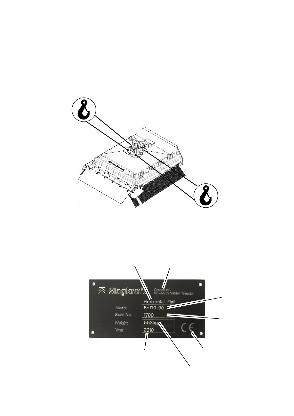
Lifting points
The horizontal flail has four points that are to be used when lifting. These lifting
points are marked with decals as illustrated below.
Type plate
The type plate on the machine is as illustrated below.
Year of
manufacture
Address to
Cranab AB
Machine weight
Machine serial
number
Machine type
designation
Product name
CE-Marking
Declaration of conformity
on last page

20
6
C
ONNECTING TO CARRIER
Slagkraft’s horizontal flail can be mounted on other carriers than Slagkraft
cranes. Slagkraft’s tilting mounts are therefore available in a variety of designs.
It is essential that an inspection is made after fitting to ensure satisfactory
stability. To inspect, extend the crane boom and flail to maximum reach, at right
angles to the direction of travel of the base machine, just above the ground. If
the machine is unstable it is to be balanced with counterweights and/or
stabilising cylinder before being used.
The tilt mount or the marked lifting points must be used to lift the horizontal flail.
Hoses
In cases where the horizontal flail is delivered without hoses the
recommendations below are to be followed when choosing hydraulic hose.
Hose dimensionFunction
inches mm
Working
pressure
bar
Bursting
pressure
bar
Draining ½ 6.4 288 1100
Pressure 1 25.4 380 1520
Return 1½ 38 50 200
Connecting
•Ensure that fastening of the horizontal flail to the crane is secure, check
pivots and bolted joints.
•Ensure that locking lugs / bolted joints on the base machine are fitted
correctly.
•Ensure that pressure and rate of flow are correct (see technical data).
•Recommended hose dimensions are minimum 1" for pressure, minimum 1½"
for return and minimum ½" for draining. The drain hose must be connected
direct to the reservoir so that pressure cannot be higher than 3 bar. The
draining pressure can be checked at the vacant drain port on the hydraulic
motor.
•A check valve (or similar) shall be connected between the hydraulic motor
pressure- and return ports to avoid cavitation. Check valve kit is available as
option.
•The carrier must be disconnected when connecting electric and hydraulic
leads.
This manual suits for next models
6
Table of contents


