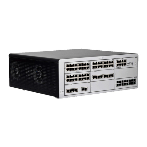
Slican IPM-032 Guide

Technical
Documentation
Telecommunication server
Slican IPM-032
Issue 1.01

Technical documentation
SLICAN Sp. z o.o.
www.slican.pl
e-mail:[email protected]
IPM-032 PABX includes software made available in accordance with the GN General Public
Licence, Mozilla Public License and BSD licences. The content of the licence is included on an
attached CD.
"The manufacturer retains the right to modify the product without prior notice".
Date of last mo ification:30/09/2013
2

Slican IPM-032
Contents
1 Basic parameters and features of the Slican IPM-032 telecommunication server.................5
1.1 General............................................................................................................................5
1.2 Functional features..........................................................................................................5
1.3 Support and terminals.....................................................................................................5
1.4 Line range.......................................................................................................................6
2 Slican IPM-032 server architecture........................................................................................7
2.1 General............................................................................................................................7
2.2 Marking of servers and shelves of IPM-032 system.......................................................7
2.2.1 List of servers and processing units of IPM-032 system...............................................8
2.3 Marking of terminals (port outputs)................................................................................8
3 Slican IPM-032 server base elements....................................................................................9
3.1 Version 2 .......................................................................................................................9
3.1.1 Card installation..........................................................................................................10
3.2 Version WM..................................................................................................................13
3.2.1 Card installation..........................................................................................................15
3.3 Batteries........................................................................................................................18
4 Port modules........................................................................................................................19
4.1 Max. number of equipment modules in an IPM server.................................................20
4.2 Controller cards.............................................................................................................21
4.2.1 Controller card IPM1AP ...........................................................................................21
4.2.2 Controller card IPM1LP - "LowCost”......................................................................23
4.3 Submodules installed in the controller..........................................................................24
4.3.1 Electronic server number sub module – SDN.............................................................24
4.3.2 Sub module DSP-2V (VoIP codecs) does not apply to IPM1LP ...............................24
4.3.3 Sub module DSP-AM (analogue modem) does not apply to IPM1LP .....................24
4.4 Route card E1 (ISDN-PRA)..........................................................................................25
4.5 ISDN-BRA digital port card.........................................................................................26
4.6 Card for digital system phones......................................................................................27
4.7 Analogue trunk port and subscriber port hybrid card....................................................29
4.8 Analogue internal port card...........................................................................................31
4.9 Automation and notification card..................................................................................33
4.10 GSM trunk cards.........................................................................................................35
4.10.1 IPM2GSM card (to 2SIM).........................................................................................35
4.10.2 IPM1GSM card (to 1SIM).........................................................................................36
4.11 Shelf power supply modules.......................................................................................37
4.11.1 Power supply card IPM1PS.......................................................................................37
4.11.2 Power supply card IPM1LPS for operation with IPM1LP controller.....................38
4.11.3 Battery management sub module...............................................................................39
5 Installing the system.............................................................................................................40
5.1 Assembly requirements.................................................................................................40
5.2 Buffer power input........................................................................................................40
6 System Telephones and consoles.........................................................................................40
6.1 Connecting additional consoles to CTS-202/CTS-203.IP system phones....................40
6.1.1 Variant 1 – consoles powered by a power device connected to CTS...........................41
6.1.2 Variant 2 – two consoles powered by CTS, the remaining by a power device............41
6.1.3 Variant 3 – All consoles powered by a power device..................................................42
6.2 Compatibility of power supply device for system phones and consoles......................42
7 Connectors and interfaces....................................................................................................43
7.1 Computer interfaces in IPM-032 servers......................................................................43
Issue 1.01 3

Technical documentation
7.2 Telecommunications interfaces.....................................................................................43
8 Slican IPM-032 server technical specifications...................................................................44
9 Safety requirements for operating Slican IPM-032 servers.................................................45
9.1 Installation and servicing..............................................................................................45
9.2 Workplace Environment................................................................................................45
9.3 Electrical requirements..................................................................................................45
10 Certificate of Conformity and Correct Product Disposal...................................................46
4

Slican IPM-032
1 Basic parameters and features of the Slican IPM
032 telecommunication server
1.1 General
The Slican IPM-032 telecommunication server is intended for small and medium companies. It is
available as a wall-mounted (WM) version or for installation in 19" racks (2 ).
1.2 Functional features
ξ
VoIP functionality available in basic configuration,
ξ
scalable, modular construction,
ξ
remote management using a PC via LAN, Internet or modem (optional),
ξ
LCR – intelligent routing of outgoing calls to optimise costs, reliability, networking,
ξ
monitoring operating parameters in real time, from inside the managing application,
ξ
dedicated digital system and VoIP system Slican phones,
ξ
option to configure system phones from inside the application managing the server,
ξ
managing the costs of calls and call tariffs by using the internal server mechanisms and an
additional application – BillingMAN,
ξ
99 voice announcements (DISA/infolines or a DND message),
ξ
subscriber services confirmed with voice messages,
ξ
operates with PC applications.
1.3 Support and terminals
ξ
analogue ports of extension phones with pulse dialling and DTMF,
ξ
full functionality for phones with DTMF,
ξ
internal CLIP signalling and transfer of public signals,
ξ
configurable ISDN ports at BRA 2B+D terminal (int./ext.),
ξ
Connectors:
- ISDN 2B+D – DSS1 protocol (E RO – ISDN), MSN and DDI
- ISDN 30B+D – DSS1 protocol (E RO – ISDN), DDI
- public analogue lines (POTS), according to ASS signalling,
- GSM – Tri-Band 900/1800/1900MHz
- VoIP – according to SIP (v.2.0), IAX (v.2.0), SSL (Slican Smart Link),
- p0 – terminals for digital system phones,
ξ
Interfaces:
- LAN, WAN – Ethernet 10/100 Mbps,
- SB 2.0,
ξ
support of Slican doorphones and Slican DPH access control system,
ξ
power supply from alternating current network ~230V, 50Hz,
ξ
maximal power consumption 65W,
ξ
protection of cards against over voltage in the telecommunications network,
Issue 1.01 5

Technical documentation
1.4 Line range
Type of line Range
E1 1500 m with AWG-22 1 twisted pair wire
S/T
(point-to-point) 1000 m for 0.6 mm2 cable, 120 nF
S/T
(point-to-
multipoint)
750 m for 0.6 mm2 cable, 120 nF
POTS (ASS) According to OTR – Operator’s Technical Requirements (TP S.A.) – the maximum
loop resistance for direct current: 1800 Ω with the end-use device (for the cable
only - about 1200 Ω)
LAN/WAN 100 m – only for an unshielded twisted-pair wire, class 5 (length of cable between
the devices; VoIP subscriber can be located in any area)
Up0
(terminal for
CTS)
Cable
length
CTS102,
CTS202,
CTS330
CTS202
+
console
CTS202
+ 2x
console
CTS202
or
CTS330
+
power
supply
unit
CTS202
+
console
+
power
supply
unit
CTS202
+ 2x
console
+
power
supply
unit
200m √ √ √ √ √ √
400m √
X √ √ √
600m
X X √ √ √
800m
X X √ √ √
1000m
X X √ √ √
√ - correct operation
–
correct operation, except Hands Free mode
X – incorrect operation possible
(the table lists maximum coverage values for the an 0.6 mm2 cable. The coverage
may vary, depending on the cable used and possible interference; in the case of an
AWG-261 twisted pair wire, the maximum range for a phone with a power supply
unit is up to 1300 m. The table above applies to maximum coverages for
connecting two consoles and rules for connecting additional consoles – for more
than two see the next chapter).
AB
(analo ue
subscriber)
about 4000 m for 0.5 mm cable
1 AWG – American Wire Gauge
AWG-22 – twisted-pair wire, wire outer diameter 0.64516 mm, 55 Ω/km
AWG-26 – twisted-pair wire, wire outer diameter 0.40368 mm, 143 Ω/km
6

Slican IPM-032
2 Slican IPM 032 server architecture
2.1 General
Slican IPM-032 telecommunication server with a single processing unit. Three controller versions are
available:
″
IPM1AP – Alone Processor nit,
″
IPM1LP – LowCost Processor nit, i.e. 4 VoIP channels, no support for batteries, no cards
IPM1E1, IPM32VoIP and submodules SM.DSP-2V as well as SM.DSP-AM,
″
IPM1DP 2 – Distant Processing nit;
2.2 Marking of servers and shelves of IPM 032 system
IPM-032 server has a modular construction. Different versions available within the basic version. All
versions include:
″
housing (two models)
″
main board (two models)
″
power (two models)
″
controller (three models)
The index of the specific product is made up of the of the variants listed above:
IPM-032.ab.c
where:
″
IPM-032 – product family;
″
a – single letter:
″
A – (Alone) single unit server;
″
L – (LowCost) single unit server with limited capability;
″
b – number of slots x maximum number of ports:
″
6x4 – six slots with 4 ports each (max. capacity 6*4 = 24);
″
8x4 – eight slots with 4 ports each (max. capacity 8*4 = 32);
″
c – type of housing (installation):
″
WM – wall-mounted housing;
″
2 – cabinet or euro rack mounted (19'');
2 planned
Issue 1.01 7

Technical documentation
2.2.1 List of servers and processing units of IPM 032 system
The combination of the variants listed above gives:
″
IPM-032.A8x4.2U - "Alone" server, up to 32 ports, 2 -19" housing. Controller
IPM1AP , power pack MPS-36-65, power module IPM1PS, base board 8 slots IPM8BAZ.
″
IPM-032.A6x4.WM - "Alone" server, up to 24 ports, wall mounted housing.
Controller IPM1AP , power pack MPS-36-65, power module IPM1PS, base board 6 slots
IPM6BAZ.
″
IPM-032.L8x4.2U - "LowCost" server, up to 32 ports, housing 2 -19". Controller
IPM1LP , power pack MPS-36-45, power module IPM1LPS, base board 8 slots IPM8BAZ.
″
IPM-032.L6x4.WM - "LowCost" server, up to 24 ports, wall mounted housing.
Controller IPM1LP , power pack MPS-36-45, power module IPM1LPS, base board 6 slots
IPM6BAZ.
2.3 Marking of terminals (port outputs)
The physical server terminal number has the following format:
X-Y-Z
where:
X – no. of server processing unit: 1,
Y – slot number: 1...6 (for WM), 1...8 (for 2 )
Z – port number of the port card: 1...4.
Slot number
Shelf number 1 2 3 ... 6 7 8
1
(shelf) 1-1-Z 1-2-Z 1-3-Z ... 1-6-Z 1-7-Z 1-8-Z
Table 1.: Terminal numbering in servers IPM-032
8

Slican IPM-032
3 Slican IPM 032 server base elements
3.1 Version 2U
•installation method – installation in 19" cabinets.
•access to extension cards – after opening a drawer and removing cover
•dimensions – 2 (width 483 mm, height 91 mm, depth 310 mm).
•There is a “Shelf NO” field on the front panel located between the power pack and controller
module for writing the number of the shelf
•Slot numbers are placed on the front panel, next to the card type, to facilitate navigation
between socket numbers.
The back of the housing includes power socket, ground terminal, ventilation openings and a
nameplate.
The following slots and outputs can be found on the base plate, from the left:
•PS slot – for installing a shelf power supply card
•P slot – for installing the controller
Issue 1.01 9
Figure 3 1: IPM-032.A8x4.2U – front view of housing partially populate with car s
Figure 3 3: IPM-032.2U - base plate
Figure 3 2: IPM-032.2U – back of the housing

Technical documentation
•slots from 1 to 8 – for installing expansion cards; only slots 3 and 4 support IPL1E1 or
IPL32VoIP cards.
•FAN socket – for connecting a shelf fan
•(+ / –) – for installing a shelf power supply unit
The openings in the housing increase the air circulation and lower the risk of too-high temperatures.
3.1.1 Card installation
Read the description for the card in the chapter on port modules before installing expansion cards.
Install cards with power off, some cards should be installed in dedicated slots (controller, power
supply card, E1 card,...).
Figure 3 5: IPM-032.A8x4.2U - installation of car s - step 1
10
Figure 3 4: IPM-032.A8x4.2U – si e view.

Slican IPM-032
Figure 3 6:
IPM-032.A8x4.2U - installation of car s - step 2
Issue 1.01 11

Technical documentation
Figure 3 7: Figure 3.6: IPM-032.A8x4.2U - installation of car s - step 3
12
Figure 3 8: Figure 3.6: IPM-032.A8x4.2U - installation of car s - step 4

Slican IPM-032
3.2 Version WM
″
installation method – wall mounted
″
access to extension cards – after opening a drawer and removing cover
″
dimensions – width 252 mm, height 276 mm, depth 120 mm
The description of individual control lights is given in the description of the controller card. The figure
above also shows the location of holes for mounting on the wall.
There is a switch and nameplate on the left side of the housing. Fixing handles can be seen at the back
of the housing.
Issue 1.01 13
Figure 3 9: IPM-032.WM – front view of the housing
Figure 3 10: IPM-032.WM – si e view of the housing

Technical documentation
The following slots and outputs can be found on the base plate, from the left:
•PS slot – for installing a shelf power supply card
•P slot – for installing the controller
•slots 1 to 6 – for installing expansion cards; only slots 3 and 4 support IPL1E1 or IPL32VoIP
cards.
•(+ / –) – for installing a shelf power supply unit
14
Figure 3 11: IPM-032.WM - base plate

Slican IPM-032
3.2.1 Card installation
Read the description for the card in the chapter on port modules before installing expansion cards.
Install cards with power off, some cards should be installed in dedicated slots (controller, power
supply card, E1 card,...).
Issue 1.01 15
Figure 3 12: IPM-032.WM - car installation - step 1
Figure 3 13: IPM-032.WM - car installation - step 2

Technical documentation
16
Figure 3 14: IPM-032.WM - car installation - step 3
Figure 3 15: IPM-032.WM - car installation - step 4

Slican IPM-032
Issue 1.01 17
Figure 3 16: IPM-032.WM - car installation - step 5

Technical documentation
3.3 Batteries
One type of battery capacity is available:
•BATB-3x12/7 - casing for 3x7 Ah batteries dedicated for single shelf servers.
The socket for connecting the power pack is located in the recess over the nameplate se the two-wire
cable with plug (supplied with the casing) to connect the power pack.
If it is necessary to provide power to a server shelf from a stand-alone battery pack, use cable bundle
BC-ST7.M6/25 with an ST7 plug on one end and M6 cable lugs on the other end.
Place three batteries inside the casing and connect them in series. Batteries can be installed only by a
person with applicable qualifications.
18

Slican IPM-032
4 Port modules
IPM servers have a modular construction. A server extension module is an extension card. All cards
are placed in the slots designed for them in the base board.
Name Designation
STAND-ALONE CONTROLLER IPM1AP
LOW-Cost stand-alone controller IPM1LP
Route card E1 (ISDN-PRA 30B+D) IPM1E1
2 connector card ISDN-BRA ext./int. IPM2ST
Card for 4 digital system phone ports IPM4CTS
Analogue internal 4 ports card IPM4AB
2 public line trunk card and 2 analogue internal ports IPM2CO2AB
2 gsm port card IPM2GSM
1 gsm port card IPM1GSM
2 relay and 2 sensor card IPM2RL2SN
32VoIP* module IPM32VOIP
Shelf power supply unit card IPM1PS
Shelf power supply card (installed only with IPM1LP controller) IPM1LPS
Batteries management sub module SM.3BATC
DSP sub module – 8 channels G.729 SM.DSP-2V
Analogue modem sub module SM.DSP-AM
ELECTRONIC SERVER N MBER S B MOD LE SM.SDN
NOTE!
Each time if card is replaced or mounted, make sure that the screws fixing the front panel to the server
shelf are properly tightened to achieve effective protection against any over voltage that may occur in
the added telecommunication lines. Disconnect the unit from the power network when performing
such activities.
Issue 1.01 19

Technical documentation
4.1 Max. number of equipment modules in an IPM server
Type of
module
PM-032.WM.A PM-032.WM.L PM-032.2U.A PM-032.2U.L
Remark
Max. number of
ports
Max. number
of ports
Max. number of
ports
AB 24 (6x4) 24 (6x4) 32 (8x4) 32 (8x4)
CTS 1243124312431243Together with
CTS.IP
ISDN BRA412 (6x2) 12 (6x2) 16 (8x2) 16 (8x2)
POTS 12 (6x2) 12 (6x2) 16 (8x2) 16 (8x2)
GSM 12 (6x2) 12 (6x2) 16 (8x2) 16 (8x2)
E1 2 - 2 -
IPM32VOIP 2 - 2 -
IPM2RL2SN 24 (6x4) 24 (6x4) 32 (8x4) 32 (8x4)
3 Including max. 6 IPM4CTS (WM) cards and 8 IPM4CTS (2 ) cards
4card ports can be used as external or internal ones
20
Table of contents
Popular Server manuals by other brands
ZyXEL Communications
ZyXEL Communications NSA325 Support note
IBM
IBM 86473AX Specifications

Yamaha
Yamaha MCX-2000 - MusicCAST Digital Audio Server owner's manual
Silicon Graphics
Silicon Graphics Rackable C2110G-RP5 System user's guide
HP
HP ProLiant DL380 G5 DPSS Quickspecs
Netscape
Netscape NETSCAPE ENTREPRISE SERVER 6.1 - 04-2002... Administrator's guide
Polycom
Polycom DOC2563A Installation & configuration guide
HP
HP T5540 - Thin Client - 512 MB RAM Quickspecs
IBM
IBM HS21 XM BLADECENTER - X5260 FOR SPEC CPU2006 supplementary guide
Asus
Asus Pentium 4 1U Rackmount Server AP160R-S user guide
IBM
IBM Eserver pSeries 670 user guide
Axis
Axis AXIS 243Q Blade datasheet
