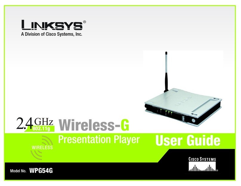
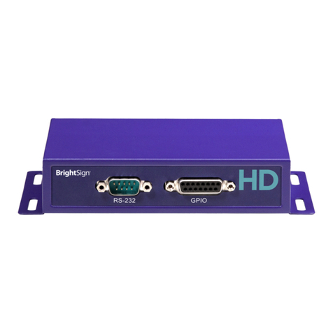
Slingbox 350 User manual

Montage Installaon Guide
1) All-in-one Integrated Touch Board
2) Kiosk Stand
3) TV Signal Converter -Sling Box (Oponal: see your
order details)
4) Camera (Oponal: see your order details)
A1. Your Enre Montage System ships in 2 crates (1 crate for the board and 1 for the Kiosk Stand) and
may also include other accessories depending on your order details:
A2. All hardware, soware, and cabling is included with your purchase. The only thing you need to
provide is a network cable for internet connecon, two AAA Baeries for the remote, and a Cable
TV box if you choose to use the Sling Box. While the device does have wireless capabilies it is
highly NOT recommended for use with the Montage Applicaon.
A3. The Montage Board itself mounts onto the Kiosk Stand via 4 screws that are already aached
onto the back of the Board. The 4 screws will simply slide into the available holes on the mounng
bracket of the Kiosk Stand. The Kiosk Stand with the mounng bracket will be shipped to you in
another crate. The Computer Unit is integrated within the Board.
A4. Actual size of board:
42’’ Board
Width: 40 1⁄4’’ Depth: 1 1⁄2’’ Height: 24 1⁄4’’
The Sling box cables to your TV signal provider, typically Comcast, Dish or Direct TV. We
support both standard and high definion. Wiring is simple and requires no special tools.
B: If you have purchased Montage 2 or later you will have cable TV compability. This will allow you
to display any cable TV signal that you subscribe to from your cable provider to appear on the
Montage board.
C: How the TV Signal travels to your Montage Board?
We recommend that you connect the Sling Box to your cable box at the point of cable entry into
your office. Typically a closet or backroom. The Sling Box converts your TV signal to a medium that
is compable with Montage. The signal is crisp and clear on the Montage board. The Sling Box
simply channels this signal through the Montage Applicaon.

Diagram on the Cabling
External Cable In INTERNET
SLINGBOX 350
SLINGBOX 350 SETUP
OUT
IN
POWER
Red
Audio
White
Audio
Red
Video
Blue
Video
Green
Video
Touch System Overview
Power & Internet
Kiosk Stand
Power, Internet, & USB Any other external devices via USB (e.g. camera)
Board’s Computer Unit
Display connecon – HDMI Cable
Board’s Monitor Unit

Diagram on the Monitor
MONITOR
HDMI
HDMI
POWER CABLE
POWER CABLE
USB
USB
INTERNET
INTERNET
POWER
POWER
HDMI 1
HDMI 2
Monitor Input
Computer Unit - Input/Output
Power cable connecon from the Kiosk Stand to the Computer Unit
HDMI display connecon for Computer Unit Monitor
USB Ports for external devices(USB 3.0 x2 slot) (USB 2.0 x2 slots)
Internet/Network connecon from the Kiosk Stand to the Computer Unit
Power buon to turn on/off Computer

Montage System Parts
The primary items for Montage will be shipped within two crates. If your order details include other
accessories (e.g. Camera, Sling Box, and etc.), the items will be shipped to you in separate smaller boxes.
Crate 1 – BOARD
1. All-in-one Integrated Touch Board
2. A sealed packet containing the HDMI cable (x1 -to connect from the Computer-side of the Board
to the Monitor), Remote Control (x1), and Power Cable (x1 – This cable should run from the Kiosk
Stand to the Board)
Crate 2 –STAND
1. Kiosk Stand
2. The frame that the Touch Board mounts on will contain three cables that will need to be
plugged into the Board aer it is mounted onto the Stand (these three cables will already be
connected to the Kiosk Stand):
• Power Cable (x1 – This cable should run from the power outlet to the Kiosk Stand)
• USB Cable (x1)
• Network Patch Cable (x 1)

Montage System Parts
Hardware Installaon
The only tools you’ll need for this installaon is a Philips Head Screwdriver since the Board itself latches
onto the Kiosk Stand via 4 screws that are pre-aached to the Board.
1. Lay the Board face down on a so surface to avoid scratches
2. Slightly loosen the 4 screws on the back of the Board so that it can slide into the available slots on the
frame of the Kiosk Stand
3. The Kiosk Stand’s USB, Ethernet, and Power cable will eventually need to be plugged into the top of the
Board so pull them underneath the Stand’s frame so that the Board will not be resng on them aer it is
mounted
4. Mount the Board and plug in the USB, Ethernet, Power, and HDMI Cable

Hardware Installaon
Once all the cables are plugged in, please follow the instrucons below to turn on the
System:
1. When connecng the HDMI from the Board’s Computer Unit Board’s Monitor, you will noce
that the Board’s Monitor will have two HDMI ports available on the le side of the Board.
Feel free to run the HDMI display cable to any of the available ports from the Board’s
Computer Unit.
2. You will need to flip the Black Power Switch located right underneath the Kiosk Stands power
connecon in order to allow power to be distributed throughout the enre Montage System
(Computer and Monitor Unit).
3. Aer flipping the Power Switch you will need to push the Round Silver Buon right next to
the power connecon situated on top of the Board’s Computer Unit – Note: the Silver Buon
will light up blue if the Computer Unit is running.
4. The Board’s Monitor should boot on automacally but if it does not, you will need to hit the
power buon on the remote control.
5. The Remote Control also controls the input opons to switch back and forth between
different video opons for the Monitor. If all you see aer the Computer turns on is a
blue-screen with “No Display Detected” then you will need to use the Remote Control to
toggle between HDMI inputs (there should be a buon labeled HDMI on the Remote Control
that allows you to switch from HDMI 1 to 2 – the correct opon will vary depending on which
HDMI Port you connected the cable to from Step 1).
Table of contents
