Sloan OPTIMA AIR EHD-700 Series Installation instructions

1
Dryer Model
Serial Number
Date Of Purchase
IMPORTANT SAFETY INSTRUCTIONS
OPTIMA AIR™HAND DRYER
EHD-700 SERIES
Sloan Valve Company warrants its Optima Air™Hand Dryer to be made of first class materials, free from defects of material or workmanship under normal use
and to perform the service for which it is intended in a thoroughly reliable and efficient manner when properly installed and serviced, for a period of five years (1
year for special finishes) from date of purchase. During this period, Sloan Valve Company will, at its option, repair or replace any part or parts which prove to be
thus defective if returned to Sloan Valve Company, at customer’s cost, and this shall be the sole remedy available under this warranty. No claims will be allowed
for labor, transportation or other incidental costs. This warranty extends only to persons or organizations who purchase Sloan Valve Company’s products directly
from Sloan Valve Company for purpose of resale.
THERE ARE NO WARRANTIES WHICH EXTEND BEYOND THE DESCRIPTION ON THE FACE HEREOF. IN NO EVENT IS SLOAN VALVE COMPANY RESPONSIBLE FOR
ANY CONSEQUENTIAL DAMAGES OF ANY MEASURE WHATSOEVER.
WARNING: For proper electrical connections, check your local building codes.
Your unit must be installed by a qualied, licensed electrician.
INSTALLATION AND OWNERS MANUAL
CONTENTS OF BOX
LIMITED WARRANTY
Tamper-Proof 5/32” Hex
security bit wrench
Knockout Gasket (Included for
use with White Model only)
Hand Dryer Installation and Owners Manual
MODEL INFORMATION
Code No. 0816863
Rev.1 (11/18)

2
READ AND SAVE THESE INSTRUCTIONS
1.Disconnect the power source previously brought to the
hand dryer location (see pre installation wiring above).
2.Use the Tamper-Proof Wrench supplied and remove the
Tamper-Proof Bolt on bottom of cover lifting upwards to
remove cover from base plate.
3.If electrical wiring entry is to be made from the rear,
remove the appropriate pre-formed knockout on the base
plate. FOR WHITE Only - If entry is to be made from the
side, knock out the pre- formed area on the right side
of cover for your supply connection using knockout gasket
provided. A rigid conduit must be used.
4.Select the appropriate mounting height for dryer (Table 1)
and fastener, as recommended (Table 2).
There should be no obstruction between the hand dryer
and the oor. If mounting over a countertop, distance from
counter to dryer must be 15” (381 mm) minimum.
CAUTION: Do not use Base Plate as a guide when
drilling. Make sure no pipe work (gas, water, air) or
any electrical cables or wires are located directly
behind the area to be drilled.
5.Attach Base Plate at the four corners to smooth wall. Use
one of 2 knockouts provided for service entry on back of
Base Plate. If using surface wiring use knockout in right
side of cover. Use Knockout Gasket supplied around
conduit for water seal. See Mounting Details.
TABLE 1 TABLE 2
SUGGESTED MOUNTING HEIGHT
from oor to bottom of dryer:
Men 45” (114 cm)
Women 43” (109 cm)
Teenagers 41” (104 cm)
Small Children 35” (89 cm)
Handicapped 37” (94 cm)
1MOUNTING HARDWARE
Recommended Fastener (not supplied):
Masonry Wall ½” Expansion Sleeve with ¼” Lag Bolt
Hollow Wall ¼” Wing Type Toggle Bolt
Wooden Wall ¼” Lag Screw With Washer
2
Check that the electrical supply corresponds to that shown-
on the rating sticker of unit. If the dryer is connected to any
electrical supply other than that stated on the rating sticker
ofthe unit, permanent damage or improper, unsafe operation
ofthe unit may result.
•Make sure electricity is switched off at the main panel
before installing, maintaining or cleaning this hand dryer.
Dryer must be installed in accordance with current local
wiring andbuilding regulations.
•Do not wire this hand dryer into the lighting circuit. It must
be protected by an independent circuit.
INSTALLATION INSTRUCTIONS
•Dryer is intended to be permanently connected to power-
supply, and must be properly grounded.
SAFETY
•Troubleshooting and internal maintenance must be
performed by qualied service personnel.
•Do not use any power wash equipment for cleaning on
or near this unit.
•Do not use the dryer for drying hair.
•Do not obstruct air inlets or outlets.
PRE INSTALLATION WIRING
INSTALLATION INSTRUCTIONS
6.Identify the voltage of your dryer from the rating sticker of
the unit. Then connect to a dedicated branch circuit not
exceeding 20 Amp. per your local wiring and building
regulations.
7.Secure electrical wiring to terminals as indicated by
the schematic afxed to blower housing. An identied
ground connection point is supplied on the Base Plate for
your equipment ground wire. Dryers should be installed per
local code requirements.
8.In multiple installations, make sure the serial number
marked on the inside matches the cover number. Then
carefully replace Cover by inserting top of cover over
bracket and tilting downward. Use Tamper-Proof Bolt
previously removed in step 2.
9.Restore power and test for proper operation.
10. Return Tamper-Proof Wrench to owner.

READ AND SAVE THESE INSTRUCTIONS
MOUNTING DETAILS
TROUBLESHOOTING
Dryer does not turn on Dryer blows only cold air
1. Check power to the unit and connections. Verify dryer is
receiving voltage at Terminal Block.
2. Check RED service LED light for the following:
Light is ON – Place hands under Sensor. If light stays on,
then replace Sensor. If light goes off, check to make sure
wiring is correct. If OK, check wire connecting to Motor. If
both are OK, replace Motor.
Light is OFF – Check for loose, disconnected or improper
wiring (See wiring schematic on blower housing) or replace
Control Assembly.
Light is FLASHING – See error codes in CODE chart
Dryer does not Shut Off
1. May be mounted too close to a counter or object (adjust
Sensor range).
2. Check for loose, disconnected or improper wiring at
Control Assembly (refer to wiring schematic afxed to
blower housing.
3. Replace Control Assembly
1. Check heat setting on control.
2. Check for loose connections to Heating Element.
3. Replace Heating Element.
Dryer does not Always turn on, or turns on by itself
1. May be mounted too close to counter or object (adjust
Sensor range).
2. Check for foreign material on Optical Sensor next to Air
Outlet.
3. Check for loose wires on Control Assembly.
4. Replace Control Assembly.
Dryer heats up but no air comes out
1.Check wire connection to Motor.
2.Replace Motor.
Dryer has loss of air volume
1. Check motor speed setting (Labeled “M”) on control. Turn
clockwise to increase.
2. Check for slow running Motor or burning smell. If so,
replace Motor.
3. Check Pre-Filter for lint buildup. Clean by removing
Pre-Filter and rinse in warm water then dry Pre-Filter
before reinstalling.
WARNING: TO REDUCE THE RISK OF FIRE, ELECTRIC SHOCK OR INJURY TO PERSONS, OBSERVE THE
FOLLOWING:
A. Use this unit only in the manner intended by the manufacturer.
B. Before servicing or cleaning unit, switch power off at service panel and lock the service
disconnecting means to prevent power from being switched on accidentally. When the service
disconnecting means cannot be locked, securely fasten a prominent warning device, such as a
tag, to the service panel.
OUTSIDE: Gently wash Cover (including air inlet holes)
using a soft cloth or sponge and a mild soap or detergent
with lukewarm water to loosen dirt and grime.
INSIDE: Sloan recommends inspecting the inside of the
dryer and cleaning as required at least once per year, or if
performance diminishes. Heavier usage, or an environment
that contains excessive lint, dust or other particles, requires
more frequent cleaning. Lint on the air inlet, the Pre-Filter,
or other internal parts of dryer will reduce efciency and
shorten the life of the working parts.
TO CLEAN: Shut off power to dryer at service connection.
Uses the Tamper-Proof Wrench supplied and remove the
Tamper-Proof Bolt on bottom of cover lifting upwards to
remove cover from base plate. Gently clean all parts using a
small, soft brush. Unclip the Pre-Filter, rinse with water and
dry. Re-install.
CLEANING / MAINTENANCEMOUNTING DETAILS
3
4
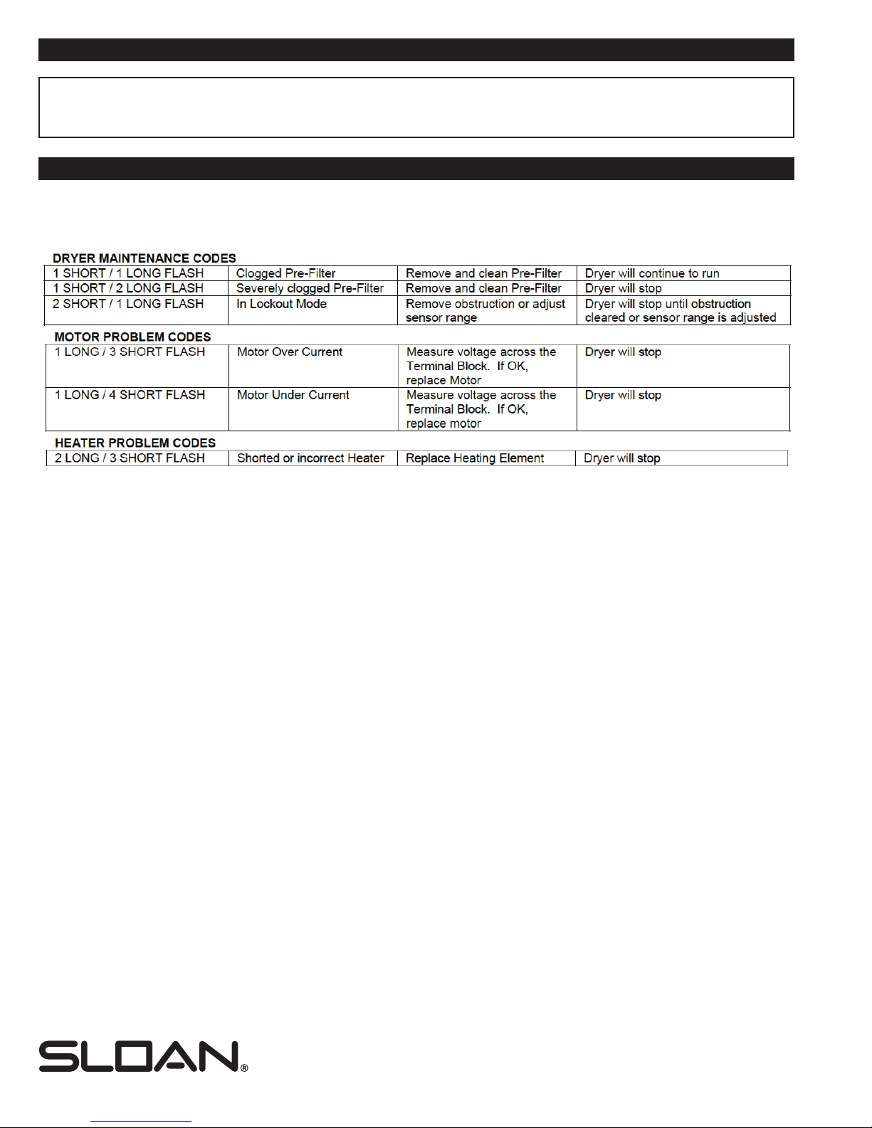
CODE CHART
Codes are displayed by the ashing of the red LED light in the sensor behind air outlet.
Normal operation will be indicated by the red LED being on when not drying and off when hands are under the sensor.
SLOAN VALVE COMPANY • 10500 Seymour Avenue • Franklin Park, IL 60131
Phone: 1-800-9-VALVE-9 or 1-847-671-4300 • Fax: 1-800-447-8329 or 1-847-671-4380
sloan.com
0816863 Rev.1 (11/18)
Copyright © 2018 SLOAN VALVE COMPANY
The information contained in this document is subject to change without notice.
ADJUSTING THE HEAT OUTPUT, MOTOR SPEED AND SENSOR RANGE
The dryer is shipped with maximum heat and maximum motor speed. To adjust, turn the corresponding knob
COUNTERCLOCKWISE to reduce. H = HEAT M = MOTOR R = RANGE
TROUBLESHOOTING (CONT.)
If problems cannot be resolved with the above troubleshooting steps, please call Sloan
at 1.888.756.2614 and one of our trained technicians will be happy to assist you.
4
Other Sloan Dryer manuals


