Sloan OPTIMA Series Instructions for use

Installation of the Sloan OPTIMA Series Electronic Hand Dryer makes
drying of hands totally “hands-free” providing the ultimate in sanitary
protection and automatic operation. There are no buttons to push. The
OPTIMA series electronic hand dryer uses fiber optic and adaptive
sensingtechnologytosensetheuser’spresenceandactivate.Whenthe
user’s presence is no longer detected, the hand dryer automatically
stops.
The OPTIMA series electronic hand dryer is designed for easy
installation and maintenance, quiet and efficient operation, and years of
dependable, trouble-free service.
The following instructions will serve as a guide when installing the
OPTIMA Series electronic hand dryer. As always, good safety practices
and care are recommended when installing your new hand dryer. If
further assistance is required, contact your nearest Sloan
Representative office.
Made in the U.S.A.
EHD l.l. — Rev. 2 (01/01)
Code No. 0816167
INSTALLATION INSTRUCTIONS AND MAINTENANCE GUIDE
OPTIMA™ SYSTEMS
SENSOR OPERATED SURFACE MOUNTED ELECTRONIC HAND DRYER
Model EHD 120
Sensor Operated Hand Dryer
120 VAC
Model EHD 208/240
Sensor Operated Hand Dryer
208 VAC or 240 VAC
LIMITED WARRANTY
Sloan Valve Company warrants its Electronic Hand Dryers to be made of first class materials, free from defects of material or workmanship under normal use and to
perform the service for whichthey are intended in a thoroughly reliable andefficient manner whenproperly installed and serviced, for a periodof five yearsfrom date
of purchase. During this period, Sloan Valve Company will, atits option, repair orreplaceanypart or parts whichprove tobe thus defective if returned to Sloan Valve
Company, at customer’s cost, and this shall be the sole remedy available under this warranty. No claims will be allowed for labor, transportation or other incidental
costs. This warranty extends only to persons or organizations who purchase Sloan Valve Company’s products directly from Sloan Valve Company for purpose of
resale.
THERE ARE NO WARRANTIES WHICH EXTEND BEYOND THE DESCRIPTION ON THE FACE HEREOF. IN NO EVENT IS SLOAN VALVE
COMPANY RESPONSIBLE FOR ANY CONSEQUENTIAL DAMAGES OF ANY MEASURE WHATSOEVER.
Listed
PRIOR TO INSTALLATION
Prior to installing the Sloan OPTIMA Series Electronic Hand Dryer,
determine the location where the dryer will be installed. Read the
following paragraph entitled “Installation Precautions” and then refer to
Table 1 and Figure 1 for recommended mounting heights.
Installation Precautions
•Mounting surface should be smooth and flat.
•Mount dryer at least 24 inches (610 mm) away from basins.
•Mount dryer at least 20 inches (508 mm) away from corners.
•Mount multiple hand dryers a minimum of 20 inches (508 mm) apart,
center to center.
•Avoid installing hand dryers in narrow hallways and behind swinging
doors.
Table 1 — Recommended Mounting Height
Users Height
Men 50 Inches (1270 mm)
Women 48 Inches (1219 mm)
Children 44 Inches (1118 mm)
Handicapped 42 Inches (1067 mm)
Prepare wall to receive mounting fasteners as shown in Figure 1. Refer
to Table 2 for recommended fasteners.
Note: A mounting template is provided to locate fastener positions.
Table 2 — Recommended Fasteners
Wall Type Fastener Type Qty.
Wall board, metal, hollow tile 1/4" Toggle Bolts 3
Stud wall, wood #14 Screws 3 †
Cement, brick, tile #12-14 Anchors 3 †
†Installation hardware provided by Sloan.
Drill a 7/8" (22 mm) minimum diameter hole in wall for electrical
connection. Install electrical line in the location shown in Figure 1.
Table 3 — Electrical Requirements
Model Voltage Amps Hz Watts
EHD 120 120 VAC 20 50/60 2400
EHD 208/240 ‡208 VAC 9 50/60 1870
EHD 208/240 ‡240 VAC 10 50/60 2400
‡Type EHD 208/240 can operate on either 208 VAC or 240 VAC per the
requirements listed.
Note: ConnectHandDryer toa separate 20amp branchcircuitfromthe
nearestelectricaldistributionpanel.UseNo.14gaugeorlargerwirefrom
electrical distribution panel to Dryer.
Important: ALL ELECTRICAL WIRING SHOULD BE INSTALLED IN
ACCORDANCE WITH NATIONAL/LOCAL CODES AND
REGULATIONS.
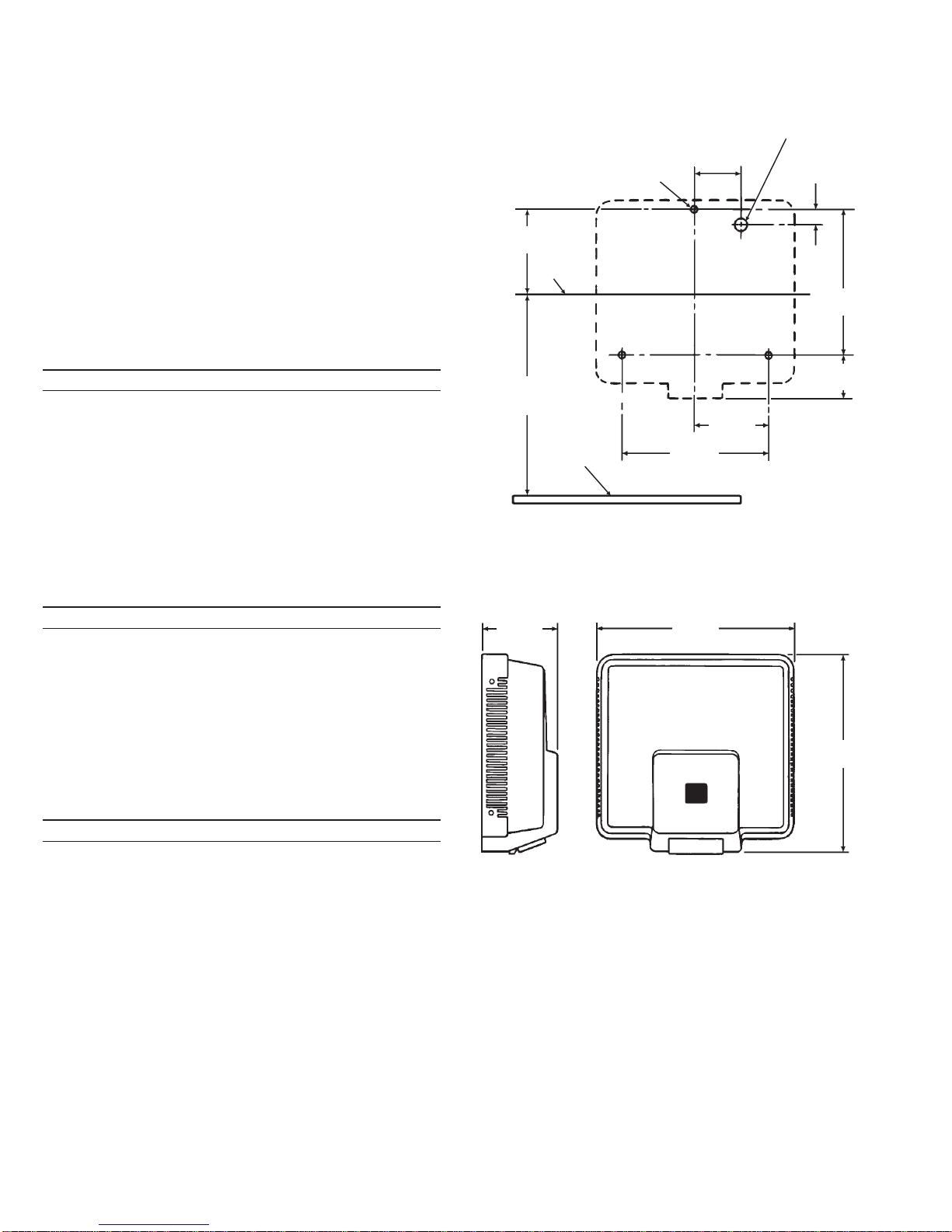
ROUGH-IN —Figure 1
MOUNTING
HEIGHT
(SEETABLE 1)
3/8" (9.5 mm) DIA.
HOLE (3) PLACES
3/4"
(19 mm)
10"
(254 mm)
LEVELLINE
4-3/8"
(111 mm)
FINISHED
FLOOR
3-1/8"
(79 mm)
7/8" (22 mm) DIA. HOLE
FOR ELECTRICAL
CONNECTION
2-3/4"
(70 mm)
C/L
5-5/16"
(135 mm) 13-3/4"
(349 mm)
13-3/8"
(340 mm)
8-3/4"
(222 mm)
5-1/2"
(140 mm)
USE MOUNTING TEMPLATE PROVIDED
2

INSTALLATION
Step 1 — Mount Chassis to Wall (Figure 1)
String electrical wires through Chassis Assembly and secure Chassis
Assembly to wall using the recommended Fasteners listed in Table 2.
Step 2 — Electrical Hook-Up (Figures 2, 3 and 4)
Becertainthatpowerisdisconnectedatthemainpowersource.Connect
electrical wiring to the Hand Dryer as shown in the appropriate wiring
diagram in Figure 2.
WIRING DIAGRAM —Figure 2
Step 3 — Test Self-Calibration and Operation
Turn on electrical power. The red LED should illuminate for
approximatelythirty(30)seconds.ThegreenLEDshouldthenilluminate,
indicating that the self-calibration procedure has completed and the
Dryer is ready for use. Place hands in the sensor’s detection zone
(beneath the exhaustport oftheDryer). TheDryer shouldstartand emit
apowerful flowofwarmair.RemovehandsfrombeneaththeDryer.The
Dryer should stop.
Step 4 — Install Cover Assembly
Install Cover over Chassis Assembly.Use a 5/32" hex wrench tosecure
using four (4) Tamper-Resistant Cover Screws and Lock Washers.
Note: Do not overtighten fasteners.
POWER
BOARD
ASSEMBLY
TAMPER-RESISTANT COVER
SCREW AND LOCKWASHER —
FOUR (4) REQUIRED
BLOWER
ASSEMBLY
GRILLE
Figure 4
HEATER
ASSEMBLY
WIRING DIAGRAM
LABEL
FIBER OPTIC CABLE
SUBASSEMBLY
FIBER OPTIC
CONNECTOR
CHASSIS
ASSEMBLY
LED INDICATOR
LIGHTS
Figure 3
HEATER
CONNECTION BLOWER
CONNECTION
POWER BOARD
120 VAC
POWER SOURCE
L1 GND
WHT
RED
L2
BLK
WHT
HOT NEU.
THERMOSTAT
HEATER
ASSEMBLY
POWER
BOARD
RED
FIBEROPTIC
CONNECTOR
BLOWER
MOTOR
FIBER OPTIC WIRES
GRILLE
NEU.
CAUTION
1. DISCONNECT POWER
SOURCE BEFORE SERVICING.
2. POWER SOURCE SHOULD BE
PROTECTED WITH FUSE OR
CIRCUITBREAKER.
G
R
N
W
H
T
B
L
K
B
L
K
W
H
T
L2
L1
L1
L2
BLOWER
MOTOR
208/240 VAC
POWER SOURCE
L1
WHT
RED
L2
BLK
WHT
HOT NEU.
THERMOSTAT
HEATER
ASSEMBLY
POWER
BOARD
RED
FIBER OPTIC
CONNECTOR
FIBER OPTIC WIRES
GRILLE
B
L
K
W
H
T
L2
L1
L1
L2
3

SELF-ADAPTIVE SENSING
When thisHand Dryerpowers up,itautomaticallysetsitssensing range
depending on the environment in which it is installed. No mechanical
range adjustment is required.
The OPTIMA Series electronic hand dryer is factory set to operate at a
range of 4 to 11 inches (102 to 279 mm). This range should be
satisfactory for most installations.
OPERATION
The Sloan Electronic Hand Dryer operates by means of an optical
sensorydevice. Thesensorautomaticallyactivatestheunit whenhands
are placed in front of the sensor located at the exhaust port. A powerful
flowof warmairwilldryhandsinapproximately 30secondsand willshut
off automatically when hands are withdrawn, or after 60 seconds of
continuous operation.
1. The OPTIMA/EHD functions by means
of an electronic fiber optic photo-sensor
located at the exhaust port beneath the
Hand Dryer.
2. When hands are placed beneath the
exhaust port, the fiber optic
photo-sensor activates the Hand Dryer
which emits a powerful flow of warm air
to dry hands within 30 seconds.
3. When hands are withdrawn, the Hand
Dryer shuts off automatically. It is then
ready for the next user.
TROUBLESHOOTING GUIDE
FOR NEW EHD HAND DRYER MODELS MANUFACTURED SINCE
JUNE 1999 (MODELS WITH FIBER OPTIC ADAPTIVE SENSOR)
Note:Eachpowerboard hastwo(2)LED’s:agreenpowerindicatorand
a red sensor indicator. Electrical power must be supplied to Hand Dryer
for indicator lights to function.
If none of the solutions shown below works, the power board may
need to be reset; disconnect then reconnect electrical power and
retest.
I. NoairissuppliedwhenhandsareplacedinSensor’sdetection
zone.
RemoveCoverandcheckLEDindicatorlightsonthePowerBoard.
A. If green LED does NOT illuminate:
1. Power is not being supplied to dryer; check all electrical
connections and main power supply.
2. Power Board has failed; replace Power Board.
B. If a green LED illuminates first and then red LED illuminates
when hands are placed in the Sensor’s beam:
1. Blower Motor is not connected properly; check Blower
Motor leads for secure connection.
2. Power Board has failed; replace Power Board.
3. Blower Motor has failed; replace Blower Motor.
C. IfgreenLEDilluminatesfirst,butredLEDdoesNOTilluminate
when hands are placed in the Sensor’s beam:
1. Power Board or PowerBoard detection circuit hasfailed;
replace Power Board.
D. IfonlytheredLEDilluminates(greenLEDdoesNOTilluminate
when hands are removed from the Sensor’s beam):
1. Power Board or Power Board self-calibration circuit has
failed; replace Power Board.
2. OPTIMAFiberOpticCablehasfailed;replaceFiberOptic
Cable.
II. Only unheated air is supplied when hands are placed in the
Sensor’s beam.
A. Heater is not properly connected; check Heater leads for
secure connection.
B. Heater Assembly is defective; replace Heater Assembly.
III. Air cycles intermittently on and off.
A. OPTIMA Sensor blocked or out of position; clear obstruction
and make sure that it is positioned properly in Exhaust Grille.
B. The Power Board’s range feature is not functioning properly;
replace Power Board.
IV. Dryer runs continuously (will not stop).
A. Disconnect OPTIMA Fiber Optic Cable from Fiber Optic
Connector on the Power Board.
1. Ifdryercontinuestooperate, thePowerBoardhasfailed;
replace Power Board.
2. If dryer stops operating, the OPTIMA Fiber Optic Cable
has failed; replace Fiber Optic Cable.
4

TROUBLESHOOTING GUIDE (Continued)
FOROLDEREHDHANDDRYERMODELSMANUFACTUREDPRIOR
TO JUNE 1999
I. NoairissuppliedwhenhandsareplacedinSensor’sdetection
zone.
Remove Cover and check LED indicator light on thePower Board.
A.If LED does not illuminate:
1.Power is not being supplied to dryer; check all electrical
connections and main power supply.
2.Power Board has failed; replace with Sensor/Power Board
Replacement Kit.
B.If green LED illuminates and then turns red when hands are
placed in the Sensor’s beam:
1.Blower Motor is not connected properly; check Blower Motor
leads for secure connection.
2.Power Board has failed; replace with Sensor/Power Board
Replacement Kit.
3.Blower Motor has failed; replace Blower Motor.
C.If green LED illuminates but does NOT turn red when hands are
placed in the Sensor’s beam:
1.OPTIMA Sensor blocked or out of position; clear obstruction
and make sure that it is positioned properly in Exhaust Grille.
2.OPTIMA Sensorhasfailed; replacewithSensor/Power Board
Replacement Kit.
3.Power Board has failed; replace with Sensor/Power Board
Replacement Kit.
D.IfredLED isilluminated butdoesnotturngreenwhenhandsare
removed from the Sensor’s beam:
1.OPTIMASensorislockedonandunithasexceeded60second
time out; reduce range.
2.OPTIMA Sensor blocked or out of position; clear obstruction
and make sure that it is positioned properly in Exhaust Grille.
3.OPTIMA Sensorhasfailed; replacewithSensor/Power Board
Replacement Kit.
4.Power Board has failed; replace with Sensor/Power Board
Replacement Kit.
II. Only unheated air is supplied when hands are placed in the
Sensor’s beam.
A.Heater is not properly connected; check Heater leads forsecure
connection.
B.Heater Assembly is defective; replace Heater Assembly.
III. Air cycles intermittently on and off.
A.OPTIMASensorblockedoroutofposition; clearobstructionand
make sure that it is positioned properly in Exhaust Grille.
B.Range may be too long; reduce range.
C.OPTIMA Sensor has failed; replace with Sensor/Power Board
Replacement Kit.
IV. Unit is difficult to activate.
A.OPTIMASensorblockedoroutofposition; clearobstructionand
make sure that it is positioned properly in Exhaust Grille.
B.Range may be too short; increase range.
C.OPTIMA Sensor has failed; replace with Sensor/Power Board
Replacement Kit.
V. Dryer runs continuously (will not stop).
A.Disconnect OPTIMA Sensor from Power Board. If Dryer
continues to operate, the Power Board has failed. If Dryer stops
operating,OPTIMASensorhasfailed.Ineithercase,replacewith
new Sensor/Power Board Replacement Kit.
If further assistance is required, please contact the Sloan Valve
Company Installation Engineering Department at 1-888-SLOAN-14.
5

4
6
VIEW WITHOUT COVER
8
BOTTOM VIEW OF COVER
9
7
5
2
3
1
Copyright © 2001 SloanValve Company
Parts List —EHD Hand Dryer
Item Part Code Description
No. No. No.
1 EHD-93 0305427 Mounting Hardware (Not Shown)
2 EHD-127 0305438 Lock Washer (4 Required)
3 EHD-17 0305437 Cover Screw (4 Required)
4 EHD-214-A 0305574 Chassis Assembly, 120 VAC
EHD-215-A 0305540 Chassis Assembly, 208 VAC/240 VAC
5 EHD-182-A 0366002 Power Board Assembly, 120 VAC
EHD-183-A 0366003 Power BoardAssembly, 208 VAC/240 VAC
6 EHD-216-A 0305577 Blower Assembly, 120 VAC
EHD-217-A 0305541 Blower Assembly, 208 VAC/240 VAC
7 EHD-11-A 0305401 Heater Assembly, 120 VAC
EHD-14-A 0305543 Heater Assembly, 208 VAC/240 VAC
8 EHD-184-A 0366004 Exhaust Grille/Fiber Optic Cable Sub-Assembly
9 EHD-204-A1 0305709 Cover Assembly, White
EHD-204-A2 Cover Assembly, Black
EHD-204-A3 0305711 Cover Assembly, Almond
EHD-204-A4 0305712 Cover Assembly, Gray
NOTICE:The information contained in this document is subject to
change without notice.
SLOAN VALVE COMPANY •10500 Seymour Avenue• Franklin Park, IL 60131
Phone: 1-800-9-VALVE-9or 1-847-671-4300 •Fax:1-800-447-8329 or 1-847-671-4380
http://www.sloanvalve.com
Printed in U.S.A. 01/01
Table 4 — Power Board and Sensor Replacement Kits †
Production
Dates Voltage
Power
Board
Part No.
(Obsolete)
Sensor
Part No.
(Obsolete)
Sensor/Power
Board Replacement
Kit Part No.
(Code No.) ‡
1986 - 1991 120 VAC EHD-12-A EHD-13-A EHD-1006-A (3366007)
208/240 VAC EHD-65-A EHD-13-A EHD-1007-A (3366008)
1991 - 1995 120 VAC EHD-12-A EHD-234-A EHD-1006-A (3366007)
208/240 VAC EHD-65-A EHD-234-A EHD-1007-A (3366008)
1995 - 1999 120 VAC EHD-1004-A EHD-1003-A EHD-1006-A (3366007)
208/240 VAC EHD-1005-A EHD-1003-A EHD-1007-A (3366008)
†Power Boards and Sensors are no longer available for EHD Hand Dryers
manufactured prior to June 1999. When servicing this older product, both the
Power Board and Sensor must be replaced using the Sensor/Power Board
Replacement Kits listed in Table 4 above.
‡The Sensor/PowerBoard Replacement Kitsinclude Sloan’slatest technology
Power Board Assembly (Item No. 5), Exhaust Grille/Fiber Optic Cable
Sub-Assembly (Item No. 8), Wiringand Installation Instructions.
WHEN SERVICING OLDER SLOAN EHD HANDDRYERS
Sloan Valve Company is dedicated to providing sensor operated
productsthat incorporatetoday’slatestelectronictechnologies.Tokeep
pacewith thesenewtechnologiesitisoftennecessarytomake changes
to our products. Current EHD Hand Dryer Power Boards and OPTIMA
Fiber Optic Sensors will operate in older Sloan EHDHand Dryersif the
following conditions are met:
•Hand dryers built between September 1995 and June 1999 used
Power Board Assemblies EHD-1004-A (120 VAC) and EHD-1005-A
(208/240 VAC) and OPTIMA Sensor Assembly EHD-1003-A. These
unitscanbeidentifiedbyaRangePotentiometerlocatedonthePower
Board.
•Hand dryers built before September 1995 used Power Boards
EHD-12-A (120 VAC) and EHD-65-A (208/240 VAC) and OPTIMA
Sensor EHD-234-A (EHD-13-A if built before 1991). These units can
be identified by a Range Potentiometer located on the OPTIMA
Sensor (NOT on the Power Board).
IF EITHER THE POWER BOARD OR THE OPTIMA SENSOR HAS
FAILED IN AN OLDER UNIT, BOTH COMPONENTS MUST BE
REPLACED.
Note: Hand Dryers built before 1991 included a flashing indicator light
visiblethroughawindowontheHandDryerCover.ReplacementCovers
no longer furnish the indicator light; therefore, disconnect and remove
the light if replacing the Cover or OPTIMA Sensor.
6
This manual suits for next models
3
Table of contents
Other Sloan Dryer manuals


Popular Dryer manuals by other brands


Hotpoint
Hotpoint TVFS 83C instruction manual

Huebsch
Huebsch Alliance Laundry Systems DR7102WE user guide

Frigidaire
Frigidaire FEQ1442CE Factory parts catalog

Electrolux
Electrolux T5675 Service manual

Grundig
Grundig GTN 38250 HGCW User instructions

Bosch
Bosch WTW85480CS Installation and operating instructions


