Slope-dudes Midge User manual
Required Component to complete model:
1. 1mm or 1.5mm (1/16”) ply for wing sheer web
2. Ply wood or hard balsa to form wing joiner assembly
3. 6mm (¼”) Ply or hard Balsa for wing root
4. Wing joiner and tube for wing joiner
5. 3mm steel incident pegs for main wing or 3mm rear joiner and tube
6. 3mm (1/8”) ply for servo mount
7. 5mm (3/16”) balsa for Tail plane and Rudder and rudder post
8. Tail plane joiner and incident piano wire and tube
9. Control Horns / Clevises / 2mm threaded control rods / Push rod for Elevator/Tail plane / Small bore
snake and thin piano wire to suit for rudder control.
10. Diamond tape or similar for aileron hinge
11. Hinges for rudder (Mylar hinge used on prototype)
12. Optional 1.5mm Ply or plastic card for radio plate is required
13. Optional Epoxy + Micro balloons for facing wing trailing edge and aileron leading edge
14. RADIO:
Servos: Elevator / Rudder (HiTech 65MG)
Ailerons (Ripmax SD150)
Receiver
Battery (1500mAh) 2/3rd NiMH or similar
Battery Switch (Above radio spec used on Prototypes)
Wing Preparation
When you receive your wings, they will be veneered either in wood veneer or glass cloth pressed directly
on to the foam panels. Aileron will have been cut out and the recess holes for the servos will have been
already cut.
To complete wing the following will need to be completed:
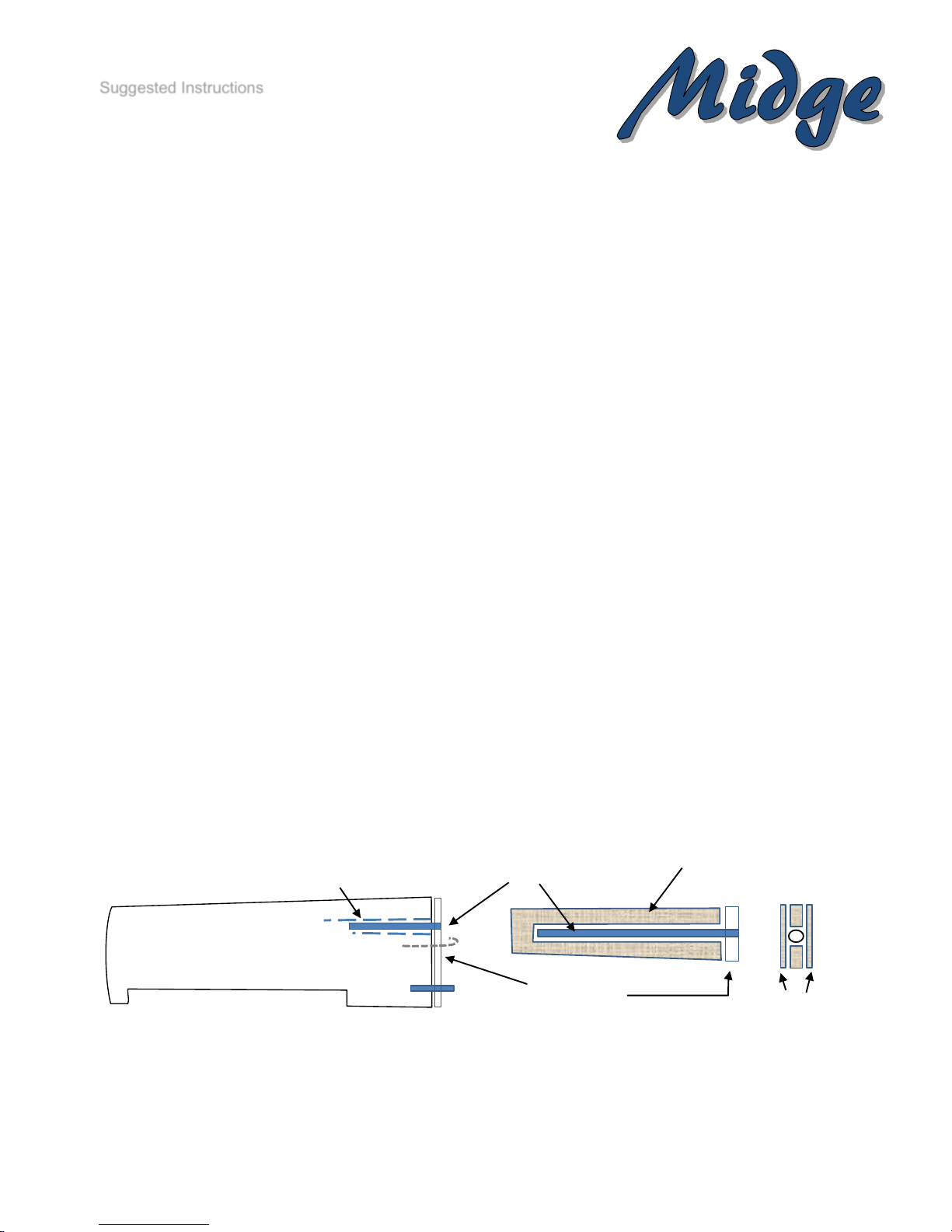
1. Install wing joiner.
2. Apply 1/4 ply reinforcement to wing root. –you will need to allow Main wing joiner and rear locating
joiner / peg to pass through. Additionally you will need to install a wire hook that passes through the
fuselage sides so a rubber bands can be used to keep wings together during use and allow for
dismantling.
Suggested Instructions
1/4” Ply or
Hard Balsa Wing Root
Brass tube to suite
wing joiner
Ply wood sheer web to reinforce
joiner assembly
Plywood / hard Balsa –
thickness to suit same thickness
of brass tube angle to achieve
5mm Dihedral under wingtip
Top
1mm or 1.5mm
ply shear web
3. Slightly hollow out the Face the mating surfaces of Trailing Edge of the wing and Leading Edge of
Aileron and fill with Epoxy and micro balloons. Alternatively, you could face with thin balsa, ply or
glass cloth.
4. Apply wood leading edge (Wood veneered wings only).
5. Cover wings (wood veneered) with chosen covering material.
6. Attach aileron using Diamond tape or similar using top hinge technique.
7. Install Aileron Servos. And attach control horn to aileron.
8. Cover servo recess with suitable cover. Either epoxy sheet or plastic card or moulded fairing.
Fuselage
The Epoxy glass fuselage will need the following tasks to complete.
1. Some filling minor imperfections in the gel coat and fuselage join may be required and rubbing
down with 600 grade wet and dry paper in readiness for paint finish.
2. Drill Holes and install brass / aluminium joiner tube to match main wing joiners.
Diamond Tape Hinge
Diamond Tape Hinge
Epoxy & micro balloon.
Aileron
Wing
Rear incident pin Hook Joiner tube
3. Drill rear main wing locator to match wing rear locator peg or 3mm rear wing joiner.
(This is easier when you have cut your wing root reinforcement ply complete with matching holes,
use this as a template to mark where the holes need to go into the fuselage. Ensure you have the
required incident of wing to fuselage angle.
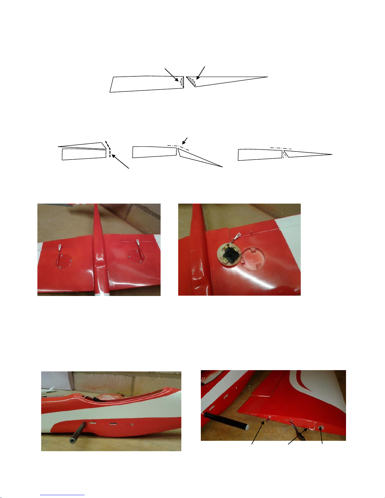
4. Drill the hole in the fin to match bell crank for the tail plane and mark and cut where incident peg
goes that will allow the tail plane to move.
5. Install tail plane bell crank. This is best if the bell crank rotates around brass tubing to suit tail plane
joiner. The pushrod should have 2mm wire with a soldered clevis to the end that connects to the
bell crank. (This will stop the clevis coming loose during use). Ensure at this time that the servo end
of the pushrod is longer than required so it can be cut back to the correct length once the decision
is made where the elevator servo will be placed.
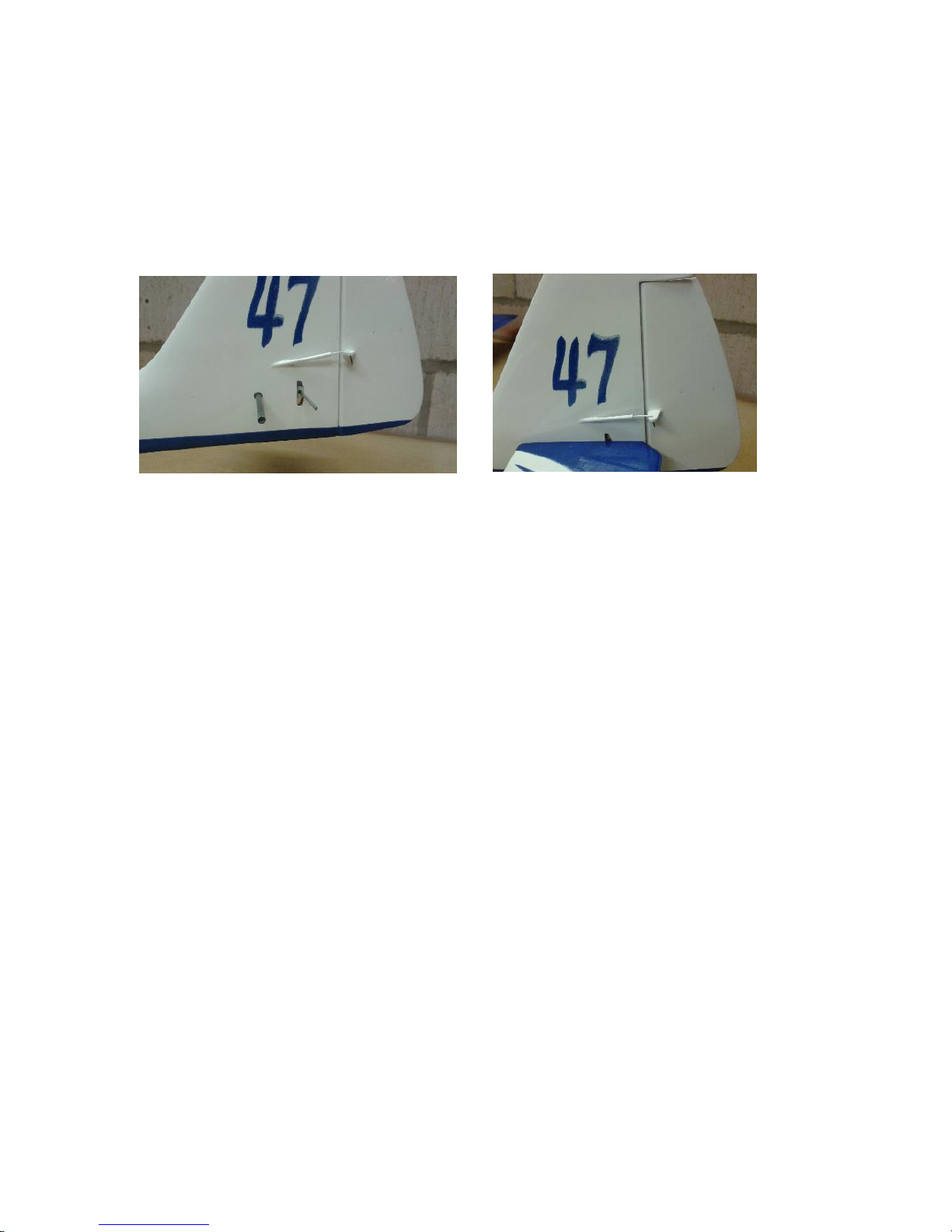
6. Install micro snake outer for rudder if one is to be fitted, and align where the rudder horn will be.
This should exit above the tail plane axis. Small gauge piano wire should be use inside the snake
for rudder control.
7. Once this has been done and everything works correctly and there is no excess movement in the
rudder snake outer (this needs to be glued to side of fuselage to prevent it from flexing
unnecessarily.
8. Install rudder post.
9. Cut and shape rudder from Balsa to match plan drawing / fuselage.
10. The rudder will need to be covered with your chosen covering material. (Solar film, Epoxy glass
etc)
11. Fabricate Tail plane as per plan drawing. This is designed to be removed for transport if required.
This needs to be sanded into an aerodynamic shape (aerofoil shape). Install tail plane joiners. Pivot
(Forward Joiner) which should pass through the pivot of the bell crank. This allows for the tail plane
to rotate around the bell crank pivot axis. The locating / activator joiner (rear Joiner) should pass
through fin and the opposite end of the bell rank to the pushrod and allow for free movement within
the recommended range of movement. Manually moving of the pushrod should provide a secure
and slop free elevator movement.

12. Once the tail plane joiner tubes have been fitted. Finally sand and cover in chosen covering
material.
13. Canopy, Use small gauge piano wire and epoxy in the centre to allow the wire to flex to allow it to
be insert under the lip at the front and rear. Of the cockpit.
You may have to put a groove in the cockpit lip or hole for the wire to pass through. See radio
installation photos below.
RADIO Gear Installation
14. Fabricate and install inside the fuselage an 1/8” ply servo mount (s) for Elevator and Rudder
servos. These can be on one ply plate or two separate mounts depending of choice of location of
servos to best suit the centre of gravity and available space. The prototype had two separate
mounts. Elevator behind the rear wing joiner tube and rudder servo between the two main wing
joiners. The second model having both elevator and rudder servos mounted on one ply plate
between the main wings.

15. The Battery and receiver can be installed directly in front of the wing inside the fuselage, but
installation is easier and more practical to remove and keep the installation neat and tidy by
fastening them onto a ply or plastic card plate that slides into the front of the fuselage in front of the
main wing joiner. My radio switch is installed on another small plywood plate and once screwed into
place, actually hold the radio plate secure.
16. To balance the model after covering / painting and with the gear installed, Lead can be cut and put
into the extreme nose of the fuselage. Assemble the model and use a small plastic bag taped to the
front of the fuselage nose where you want the lead to be and add weight until the desired balance
is achieved.
The way I make my nose weight is carry out the above to estimate the amount of lead required. I
then make a mould from slightly damp sand by pressing the nose of the fuselage (wrapped in Cling
Film) into the sand to form the shape of the nose and remove the fuselage.
Melt and pour lead into this sand mould and wait until fully cool before extracting the lead and filing
the rough surface to fit inside the nose perfectly.
WARNING: Melting lead is particularly dangerous and should not be attempted unless you have all
the necessary equipment, heat source and protective clothing and also should be done outside.
DO NOT pour lead into the fuselage, it will cause a fire and ruin your fuselage, and probably burn
you severly.
Alternatively you can add small amount of lead into the nose until you get the balance right. For fine
tuning, further lead can be added and taped to the battery plate so this can be removed later if
required.
Check and set up the controls as per the plan.
Flaps can be programmed into the aileron if desired but I would suggest no more than a few
degrees either flap (Lift setting) or reflex (Speed setting) depending on what you want. Please note
you will also need some elevator compensation for any flap settings used.
Up going ailerons can also be used as a type of CROW / BUTTERFLY braking for landing, operated
from the Throttle control of your transmitter. This control is best if proportional control is available
rather than using a switch.
Up aileron “CROW”movement to approximately 10 to 15 Degrees, which should be just enough to
get the model to sink in a flat attitude with Elevator compensation. Please note that you will still
require further up going aileron movement with aileron input to maintain roll control during braking.
And please, do not try to input too much movement as this may stall your servo. Stay within the
servo range of movement. The exact amount of required crow brake -vs- aileron movement can only
be attained through trial and error.
Rx
Batt
Lead
Switch

Flying:
Check C of G is correct.
Check all controls for correct operation and range of movement.
Pitch and role controls are lively on full so these should be kept on the lower rate setting until you
have become used to the model. I fly mine on lower rates most of the time, only increasing roll rate
when I want to lose count of the rolls I have performed (its quick).
The model can be flown in light conditions but will have to be flown appropriately. However, the model will
come alive, so to speak, in moderate to high winds with no need for additional ballast and it can reward you
with a good turn of speed.
Stalls should be straight and benign in nature if gradually induced. All expected manoeuvre are achievable
although outside loops (from the top) can sometimes be lacking due to the light weight nature of the model
and the associated lack of inertia to complete the loop. However, entering the multiple outside loops from
inverted flight at the bottom of the manoeuvre will be rewarding.
Hope you have a great time with the model.
See you on the slopes.
Table of contents
Popular Toy manuals by other brands


Hornby
Hornby 2-6-4T STANIER CLASS 4P Operating and maintenance instructions

Radio control model
Radio control model Stick Sport 90 instruction manual

V-tech
V-tech Secret Safe Diary Visual user manual

Mattel
Mattel Barbie N5030 instructions

WowWee
WowWee Robosapien X user manual

REVELL
REVELL AV-8B Harrier II plus Assembly manual

Horizon Hobby
Horizon Hobby HobbyZone AeroScout S 2 1.1m Trainer instruction manual

Rayline
Rayline R120 manual

Reely Sky
Reely Sky Trimotor Tin Goose operating instructions

B.toys
B.toys Mini Cashier Playset manual

Fisher-Price
Fisher-Price X7302-12 instruction sheet

The Learning Journey
The Learning Journey TechnoTrax Dominator instruction manual