SM Pro Audio OC8E User manual


2Safety Instructions
SAFETY INSTRUCTIONS
CAUTION: To reduce the risk of electrical shock, do not remove the cover or rear panel of this unit.
Do not expose this appliance to rain or moisture. No user serviceable parts inside.
Please refer servicing to qualified personnel only.
Retain Instructions:
Please retain all safety and operating instructions for future reference.
Ventilation:
Do not impede the flow of air through the ventilation openings. Take care when selecting appropri-
ate installation locations so obstacles do not obscure proper ventilation.
Heat:
This product should be situated away from other heat sources such as fire, high heat emitting
devices, heaters, etc.
Power Source:
Make sure the product is set to the correct voltage for the location in which it is being used.
Grounding and Polarization:
Never defeat the products power grounding means.
Power-Cord Protection:
Power supply cords should be connected or placed in a fashion that could allow possible exposure
to damage. Take care to avoid wear and tear, rubbing, squashing, etc.
Cleaning:
The product should be cleaned only with a soft cloth. Do not use any corrosive products on the unit.
Inactivity:
The power cord of the product should be unplugged from the outlet when left unused for a long
period of time.
Service requirement:
Service by qualified service personnel when:
- The power supply cable has been damaged in any way
- Liquid has been spilled onto or into the product
- The product has been exposed to rain
- The product exhibits faults or obvious performance degradation
- The product has been damaged in a way that exposes components
The user should not attempt to service this product beyond what is described in this operating man-
ual. All other servicing should be referred to qualified service personnel.

3Foreword - Features
FOREWORD
Dear Customer,
Firstly, we would like to thank you for purchasing our OC8E multi-channel compressor. With
much thought and effort, our engineers have developed a product we know you will be satisfied
with. We always guarantee you uncompromising quality as well as excellent audio properties at
an affordable price.
Please read this manual thoroughly to best understand the safety and operational procedures
of the OC8E.
Regards,
SM ProAudio
OC8E Main Features
The OC8E is a professional multi-channel optical compressor featuring:
- 8 x fast electro-optical compressor modules
- 8 x VU Meters (output meter)
- Adjustable attack, release, and compression threshold
- Low noise, wide bandwidth and superior transient response
- Class A transformerless high voltage signal path
- Bypass/on switch per channel
- Peak LED indicator per channel (input peak)
- 1/4" line level Inputs & Outputs
- 110v-240v Internal power supply
-Size:2URack
- Optional ADAT interface available (PR8IIA)
* It should be pointed out, that extreme output volumes may damage your ears and/or your head-
phone units. Turn down the LEVEL controls before you switch on the unit.

4Ta b l e o f C o n t e n t s
TABLE OF CONTENTS
SAFETY INSTRUCTIONS 2
OC8E Main Foreword and Features 3
1. INTRODUCTION 5
2. THE DESIGN 5
2.1 High quality components and design 5
2.2 Inputs and outputs 5
3. INSTALLATION 5
3.1 What’s included in the box 5
3.2 Rack-mount installation 5
3.3 Mains Voltage & front panel power switch 6
Mains Voltage 6
Power on/off switch & LED power indicator 6
3.4 Audio Connections 6
Analog Inputs 6
Analog Outputs 7
4. FRONT PANEL CONTROLS & INDICATORS 7
4.1 Independent (8x) comp on/off bypass switches 7
4.2 Independent (8x) peak led indicators 7
4.3 Independent (8x) rotary compression threshold encoders & led indicator 7
4.4 Independent (8x) rotary attack encoders 7
4.5 Independent (8x) rotary release encoders 7
4.6 Independent (8x) rotary output encoders 7
4.7 Independent (8x) VU Meters 8
5. APPLICATION 8
5.1 General use of the OC8E 8
5.2 PR8IIA - Optional ADAT output module (also known as EP84ADAT) 8
6. SPECIFICATIONS 9
7. WA R R A N T Y 10
7.1 Warranty card and/or website registration 10
7.2 Warranty 10
7.3 How to request a return authorization number 10
7.4 Warranty regulations 11
7.5 Transferability 11
7.6 Damage claims 11
7.7 Other warranty rights 11

5 Introduction - Design - Installation
1. INTRODUCTION
In purchasing the new SM OC8E you have acquired a multi-channel optical compressor of high
class that meets many of the demands of the home/pro studio. The OC8E is a 2U standard 19"
rack-mount multi-channel optical compressor that builds on the success of the SM Pro Audio ana-
log series products.
With eight discrete high-quality optical compressors, the SM OC8E seamlessly fits into many audio
workstation configurations. It features 8 x optical compressors in a simple to operate 2RU unit
device. Tailored to suit a wide variety of applications, the OC8E is perfectly suited for use as a multi-
channel compressor for many applications. Optical compressors are sought after for the distinctive
musicality they give to vocals, guitars and other instruments. The SM OC8E's adjustable ratio,
attack, release and output controls are designed to generate a distinctive soft, rich character while
providing magnificent control over dynamics. Fantastic for use as inserts on your multi-channel
recording tracks!
The OC8E also has provision for the optional installation of SM Pro Audio’s PR8IIA ADAT output
interface (also known as the EP84ADAT). The PR8IIA can provide users with the ability to output
eight (8) channels in ADAT optical light-pipe format. The PR8IIA ADAT output board is perfect for
users wanting to interface or add eight (8) additional channels of quality pre-amplification to a vari-
ety of digital devices such as digital mixers, audio recording interfaces, etc.
2. THE DESIGN
2.1 High quality components and design
The philosophy behind SM Pro Audio products guarantees a no-compromise circuit design and
fault-tolerant component selection. All SM Pro Audio products go through a rigorous planning and
production procedure from start to finish.
2.2 Inputs and outputs
All inputs and outputs are secured firmly to the exterior chassis housing thus ensuring robust qual-
ity and confidence under all conditions.
3. INSTALLATION
Your SM Pro Audio OC8E was carefully packed in the factory and the packaging was designed to
protect the unit from rough handling. Nevertheless, we recommend that you carefully examine the
packaging and its contents for any signs of physical damage, which may have occurred in transit.
* If you happen to receive a damaged unit, please notify your dealer and shipping company
immediately.
3.1 What’s included in the box
You should have the following included inside your shipping box:
- 1 x OC8E Multi-channel optical compressor
- 1 x Power cable
- 1 x Operational user guide (the one you are reading!)
3.2 Rack-mount installation
The SM Pro Audio OC8E can be used stand alone on your desktop, however it is best installed into
“two” standard 19” compatible audio rack-mount unit spaces.
Please remove all cables (including power) before installing the OC8E into your audio rack.
6Installation
Sturdy rack mounting ears are present on each side of the OC8E’s front panel. Simply mount the
OC8E into an available 2 rack-space position and secure with rack-mount bolts/screws.
* Note: Please take into consideration ventilation of your equipment. A well-ventilated equipment
rack will ensure optimum operation and longevity of your equipment. It’s often a good idea to leave
1 free rack-bay position between your equipment to allow ventilation As to avoid overheating,
please do not place the OC8E on high temperature devices such as power amplifiers.
3.3 Mains Voltage & front panel power switch
Mains Voltage
Important - Before you connect your OC8E to the mains power supply, please make sure that your
local voltage matches the voltage required by the unit!
The OC8E has a professional internal power supply suitable for operation between AC 110/115v –
AC 220/230/240v. A voltage configuration switch on the left hand side of the rear panel should be
set to match the appropriate voltage of your mains power supply. Simply slide the selector switch
with your finger or a small flat-blade screwdriver to either the 110v or 220v position to configure the
unit accordingly.
To connect the OC8E to your mains power source simply connect the included standard IEC mains
power cable to the OC8E’s three (3) pin power connector socket.
Power on/off switch & LED power indicator
The OC8E’s power switch can be found on the right hand side of the front panel. To enable power
to the OC8E or ‘turn on” simply place the power on/off switch into the down position. The LED power
indicator will illuminate to indicate the OC8E’s operational state as ‘on’ and ready for operation.
To power down or ‘turn off’ the OC8E, simply place the power on/off switch into the up position. The
LED power indicator will not illuminate to indicate the OC8E’s operational state as ‘off’.
* It’s always good practice to protect your ears, and other audio equipment by taking appropriate
care when powering up any audio equipment. Being aware of your gain structure, and performing
a structured power up sequence with your equipment will help to avoid unexpected audio signals
bursts. It’s a good idea to power up devices in sequence from the start of the signal chain to the
end of the signal chain (OC8E -> recording device -> power amplifier/active monitors).
3.4 Audio Connections
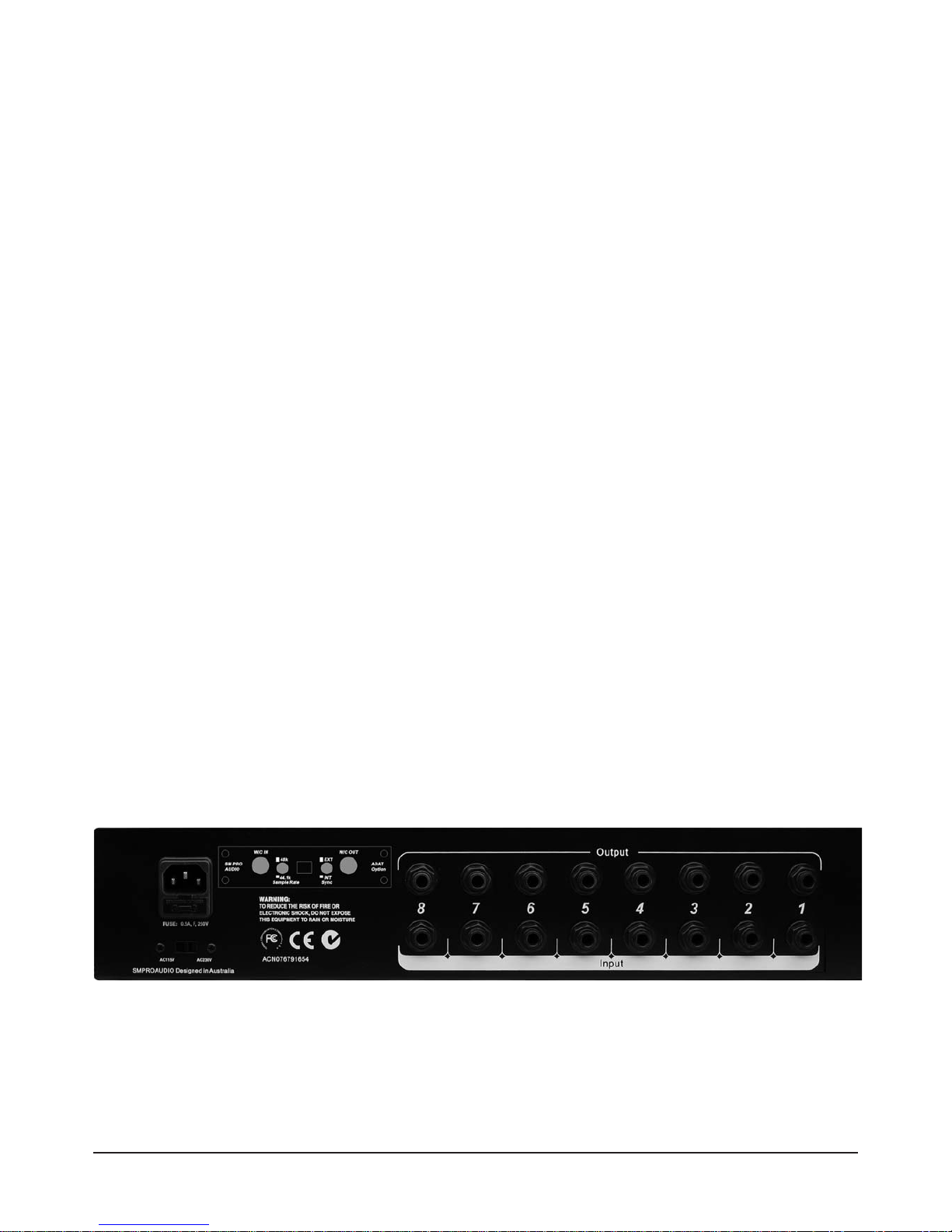
Analog Inputs
8 x ¼” TS input connectors can be found on the rear panel. These are the direct analog inputs
to the OC8E’s 8 x individual compressor modules. Input your audio source material directly to
these inputs.
OC8E rear panel
7Installation - Front Panel Controls
Analog outputs
8 x ¼” TS analog output connectors are provided for each of the eight (8) compressor channels.
Individual output levels can be controlled via the associated channels rotary output gain control
encoder on the front panel.
4. FRONT PANEL CONTROLS & INDICATORS
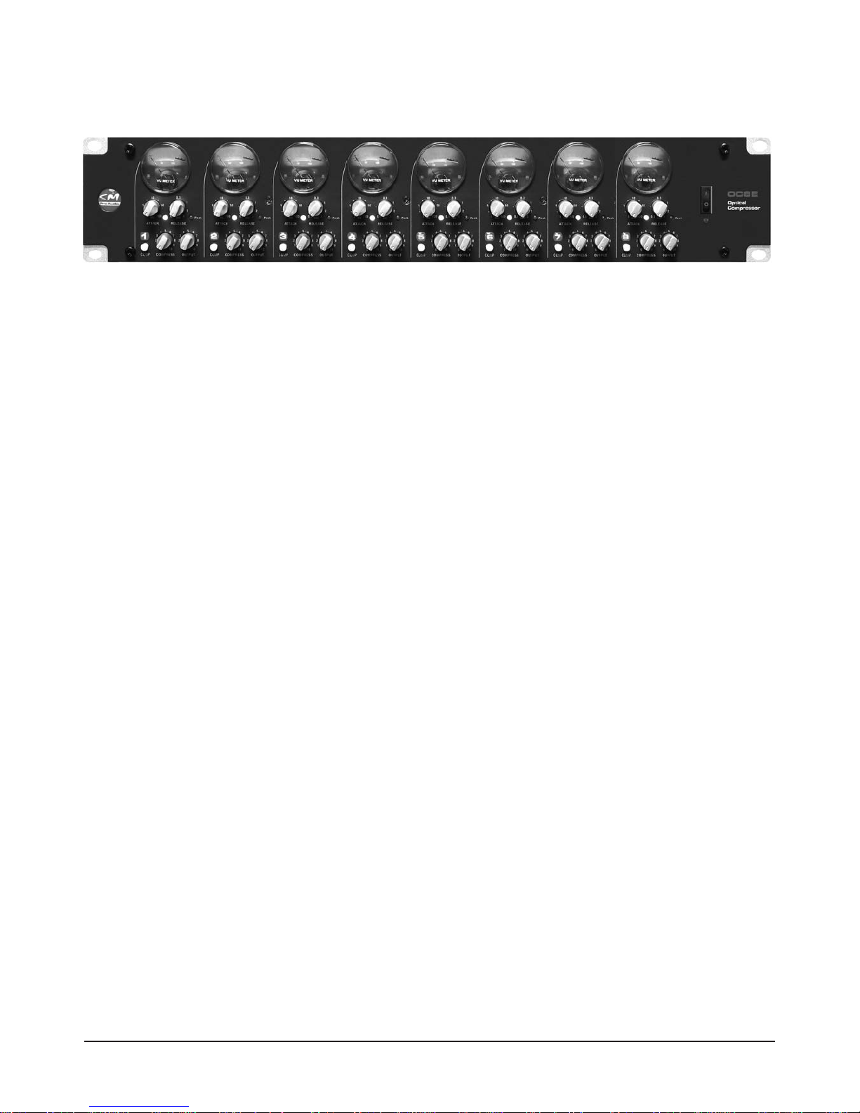
4.1 Independent (8x) comp on/off bypass switches
The COMP switch toggles the channel bypass functions for each compressor module on or off.
* This is very handy for comparing compressed audio with your original non-compressed audio pro-
gram material.
4.2 Independent (8x) peak led indicators
Each channel features a peak light LED indicator. This momentarily indicates when the input sig-
nal strength has reached optimum input level.
* A continuously illuminated peak LED indicates you have surpassed optimum input level and dis-
tortion of the respective channels audio signal will occur. It’s time to adjust your input gain structure!
4.3 Independent (8x) rotary compression threshold encoders & tri-state led indicator
Each compressor modules COMPRESS encoder acts as a threshold adjustment. When input level
is below the threshold the signal is unaffected. When input level exceeds the threshold attenuation
of the output signal occurs.
A tri-state LED is available which indicates the following:
Green – Compressor module active,
Yellow/Orange – mild compression, input signal has exceeded the threshold level
Red – heavy compression, signal level has exceeded the threshold setting considerably
4.4 Independent (8x) rotary attack encoders
The rotary attack controls allow for adjustment in milliseconds the time it takes each compressor
module to respond to the corresponding input signals before gain reduction occurs. Short attack
times quickly bring down the level of the loud, fast transients in the audio signal; long attack times
let more sound through before the compressor engages, resulting in a punchier sound.
4.5 Independent (8x) rotary release encoders
The release controls set the time in seconds it takes for each compressor modules gain to return to the
point of no gain reduction in the absence of audio program material. Short release times create a more
exaggerated effect ("breathing"), whereas long release times have a more gradual, natural sound.
4.6 Independent (8x) rotary output encoders
The rotary output controls set the output level of each compressor module. Often after reducing the sig-
nals dynamic range with processing such as compression, you require a process to ‘make-up’ the lost
OC8E front panel

8 Front Panel Controls - Application
gain. The rotary output control allows you to adjust or ‘make-up’ gain at the compressor output stage.
* Keep an eye on your VU meter to check the output signal strength!
4.7 Independent (8x) VU Meters
8 x accurate needle meters are provided for monitoring the output level of each corresponding com-
pressor module. Each meter displays scale marks from -20 to +3dB. This indicates output signal
level.
5. APPLICATION
5.1 General use of the OC8E
The OC8E is well suited to many environments requiring smooth transparent compression pro-
cessing.
The most common application would be to use the compressor on each channel of your mixer or
digital audio systems ‘insert’ connectors. Insert connectors allow you to place a processing device
such as a compressor inline with the individual channels signal path. This makes a perfect
add-on to your mixer or digital audio system.
Step by step:
Make your physical connections ...
Place your incoming signals directly into the inputs on the rear of the OC8E. Then connect the out-
puts of the OC8E to your next audio destination. Typically your inputs and outputs would be com-
ing from a mixer or pre-amps ‘insert’ connectors so that the compressor would be ‘inline’ in your
signal path.
Set your input gain control ...
The incoming signal strength cannot be adjusted on the OC8E. It must me set prior to arriving at
the units inputs. View the LED meter to analyze the incoming signal strength in dB. This allows you
a good visual indicator so you can adjust your signal from the source (ie mixer gain, preamplifier
gain control).
Apply the desired compression settings for each channel ...
You can now choose to add some optical compression to your signal if desired. Select the com-
pressor on/off switch to the “on” position. Set your channels attack and release encoders to the
desired settings, and adjust the compression ratio rotary control until you are satisfied with the
result.
Adjust your output level ...
Simply adjust the rotary output control so that your output signal is at your desired level. It is
advised that you visually monitor the input signal level on the destination device you are sending
signal to when making output level adjustments.
5.2 PR8IIA - Optional ADAT output module (also known as EP84ADAT)
The PR8IIA is an optional output module that can be fitted to the OC8E to provide pristine 24 bit
digital conversion of your OC8E’s output channels to an ADAT digital format stream. Perfect for use
with ADAT compatible mixers, multi-track recorders, ADAT PC audio cards, or other professional
ADAT compatible devices, the PR8IIA upgrades your OC8E to fit seamlessly into the digital world.

9Application - Specifications
Many of today’s computer based digital recording interfaces feature a mixture of both analog and
digital inputs and outputs. Often systems may only be able to input 8 analog sources to the system
simultaneously. Additional inputs may be provided in the form of an 8 channel digital ADAT format
input. This is where a unit like the OC8E fitted with the PR8IIA module really shines. Simply con-
nect the ADAT output of the PR8IIA to the ADAT input on your audio interface to achieve 8 chan-
nels of pristine input to your system. The PR8IIA offers internal or external sync selectors, word
clock I/O connections, and a sample rate selector switch (44.1/48kHz).
* Note: Both analog outputs from the OC8E and the PR8IIA’s ADAT digital output function simul-
taneously.
6. SPECIFICATIONS
LINE INPUTS
Connector: ¼” TS jack
Type: unbalanced
LINE OUTPUTS
Connector: ¼” TS jack
Type: unbalanced
FREQUENCY RESPONSE
Line in 6Hz to 20Hz within 1dB
COMPRESSOR
Photoresistive servo operated
Ratio minimum 1.5 to 1
Ratio maximum 10 to 1
Attack time 1 mS / 100 mS
Release time 0.1 S / 3 S
VU METERS
-20to+3dB
PERFORMANCE
THD (Unweighted) 0.05%
Signal to noise >93dB
POWER
Type: Internal 110v-220v
SM Pro Audio is constantly striving to maintain the highest professional standards. Modifications
may be made over time to improve the performance and operation of this unit. As such, specifica-
tions and appearance may differ from those listed or shown.

7. WA R R A N T Y
7.1 WARRANTY CARD &/OR WEBSITE REGISTRATION
To be protected by this warranty the purchaser of the product must complete an SM Pro Audio prod-
uct registration procedure.
Product registration is available via two methods:
Complete and return the enclosed warranty card within 14 days of the date of purchase to SM Pro
Audio (see address below).
Complete an online product registration form at the SM Pro Audio website. www.smproaudio.com
7.2 WARRANTY
SM Pro Audio warrants the mechanical and electronic components of this product to be free of
defects in material and workmanship for a period of one (1) year from the original date of purchase.
SM Pro Audio will at its sole discretion either repair or replace the product if any defects occur that
are not caused by normal wear or inappropriate use within the warranty period.
This warranty does not apply if the product has been damaged by negligence, non-authorized mod-
ifications, accident, abuse, misuse, misapplication, or as a result of unauthorized service other than
performed by that of SM Pro Audio’s service department.
All freight charges incurred for transport of justified warranty claims are at the buyer's expense.
All other warranty claims other than those indicated above are excluded.
7.3 HOW TO REQUEST A RETURN AUTHORIZATION NUMBER
To obtain warranty service, the purchaser must call SM Pro Audio during normal business hours
before returning the product (Tel.: +61 3 9555 8081). An SM Pro Audio representative will dis-
cuss any issues with you over the telephone and then issue a return authorization number if
deemed appropriate.
Please ship original shipping cartons along with your return authorization number to the following
address:
SM Pro Audio
Service Department
Warehouse 25
Roberna Business Park
26-28 Roberna St
Moorabbin 3189
Melbourne, Victoria
Australia
10 Warranty

7.4 WARRANTY REGULATIONS
- Warranty can only be serviced when accompanying proof of purchase is provided. Dealers invoice
and date stamp required.
- SM Pro Audio will endeavor to repair or replace any product under the terms of this warranty with-
in 30 days of receipt of the product at SM Pro Audio.
- Modifications performed in order to comply with any applicable technical or safety standards in any
country which is not the country for which the product was originally developed and manufactured
shall not be considered a defect in materials or workmanship. SM Pro Audio shall not be held
responsible for any costs incurred or resulting from any such modification whether performed cor-
rectly or not.
- This warranty does not cover defects of parts caused by normal operational wear. These parts are
typically switches, knobs, and other similar components.
Product damage caused by the following conditions are not covered by this warranty:
- Operation of the unit in a way that does not comply with the safety regulations applicable in the
country where the product is used.
- Damages or defects caused by conditions beyond the control of SM Pro Audio.
7.5 WARRANTY TRANSFERABILITY
This warranty is non transferable and available exclusively to the original purchaser.
7.6 DAMAGE CLAIMS
Failure of SM Pro Audio to provide proper warranty service does not entitle the purchaser to claim
further damages. SM Pro Audio’s liability shall in no way exceed the invoiced value of the product.
7.7 OTHER WARRANTY RIGHTS
This warranty does not exclude or limit any statutory rights provided by national law.
11 Warranty

The information contained in this manual is subject to change without notice.
ALL RIGHTS RESERVED © 2007 SM Pro Audio
SM Pro Audio
Service Department
Warehouse 25
Roberna Business Park
26-28 Roberna St
Moorabbin 3189
Melbourne, Victoria
Australia
PH- +61 3 9555 8081
FAX- +61 3 9555 8083
www.smproaudio.com
12 Legal Notice
Table of contents


