Vmac Underhood 70 User manual

www.vmacair.comwww.vmacair.com
Installation Manual for VMAC
System
V900132
2020+Ford F250 – F350 Super Duty
6.2 L Gas V8
UNDERHOODUNDERHOODUNDERHOODUNDERHOOD
70707070
TMTMTM
TM
AIR COMPRESSORS


VMAC - Vehicle Mounted Air Compressors
VMAC Technical Support: 888-241-2289
VMAC Knowledge Base: www.kb.vmacair.com
1
Table of Contents
Safety .........................................................................3
Warranty ......................................................................4
General Information ...........................................................6
Preparing for Installation.......................................................8
Relocating the ABS Hydraulic Control Unit (HCU) .............................14
Installing the Main Bracket and Compressor................................... 21
Modifying the Hoses, Installing the Degas Bottle, and Cooler .................27
Installing the Air Oil Separator Tank (AOST) ...................................33
Hose Requirements .......................................................... 35
Routing and Connecting the Hoses ...........................................36
Adding Oil to the System .....................................................39
Installing the Control Components ........................................... 40
Air Receiver Tank ............................................................ 44
Recommended Accessories .................................................. 45
Completing the Installation .................................................. 46
Testing the Installation........................................................47
Performance Testing and System Adjustments ............................... 50
Digital Throttle Control Operation and Adjustments........................... 51
Accessory Products from VMAC ............................................. 53
Warranty Registration ....................................................... 56

VMAC - Vehicle Mounted Air Compressors
VMAC Technical Support: 888-241-2289
VMAC Knowledge Base: www.kb.vmacair.com
2
Document: 1930410
Changes and Revisions
Revision Revision Details Revised by
Checked by
Implemented
Eng. Tech. Qual.
Mech. Elec.
AInitial Release MSP BJG ASE RDB LPH 24 Jan 2020
BECN: 20-037 MSP MRH N/A MSP AWM 30 Jan 2020
C ECN: 20-054 HCU and cooler instructions MSP CAM N/A MSP N/A 4 Mar 2020
Additional Application Information
• 2020+Ford F250 – F350 Super Duty with 6.2 L Gas V8.
• Single battery application only. Dual battery vehicles will require accessory
A900016
Important Information
The information in this manual is intended for certified VMAC installers who
have been trained in installation and service procedures and/or for anyone with
mechanical trade certification who has the tools and equipment to properly and
safely perform the installation or service. Do not attempt installation or service
without the appropriate mechanical training, knowledge and experience.
Follow all safety precautions. Any fabrication for correct fit in modified vehicles
must follow industry standard “best practices”.
Notice
Copyright © 2020 VMAC Global Technology Inc. All Rights Reserved. These
materials are provided by VMAC for informational purposes only, without
representation or warranty of any kind, and VMAC shall not be liable for errors
or omissions with respect to the materials. The only warranties for VMAC
products and services are those set forth in the express warranty statements
accompanying such products and services, if any, and nothing herein shall be
construed as constituting an additional warranty. Printing or copying of any page
in this document in whole or in part is only permitted for personal use. All other
use, copying or reproduction in both print and electronic form of any part of this
document without the written consent of VMAC is prohibited. The information
contained herein may be changed without prior notice.
Printed in Canada
Registered Trademarks
All trademarks mentioned in this manual are the property of their respective
owners. VMAC’s use of manufacturers’ trademarks in this manual is for
identification of the products only and does not imply any affiliation to, or
endorsement of said companies.
Loctite®, Loctite®242 and Loctite®567 are registered trademarks of Henkel AG &
Company KGaA.
Eaton Aeroquip® is a registered trademark of EATON AEROQUIP INC.
Ford® and Super Duty® are registered trademarks of Ford Motor Company.
VMAC - Vehicle Mounted Air Compressors
VMAC Technical Support: 888-241-2289
VMAC Knowledge Base: www.kb.vmacair.com
3
Important Safety Notice
The information contained in this manual is based on sound engineering principles,
research, extensive field experience and technical information. Information
is constantly changing with the addition of new models, assemblies, service
techniques and running OEM changes. If a discrepancy is found in this manual,
contact VMAC Technical Support prior to initiating or proceeding with installation,
service or repair. Current information may clarify the issue. Anyone with knowledge
of such discrepancies, who proceeds to perform service and repair, assumes all
risks.
Only proven service procedures are recommended. Anyone who departs from the
specific instructions provided in this manual must first ensure that their safety and
that of others is not being compromised, and that there will be no adverse effects
on the operational safety or performance of the equipment.
VMAC will not be held responsible for any liability, consequential damages, injuries,
loss or damage to individuals or to equipment as a result of the failure of anyone
to properly adhere to the procedures set out in this manual or standard safety
practices.
Safety should be the first consideration when performing any service operations.
If there are any questions concerning the procedures in this manual, or more
information is required, please contact VMAC Technical Support prior to beginning
work.
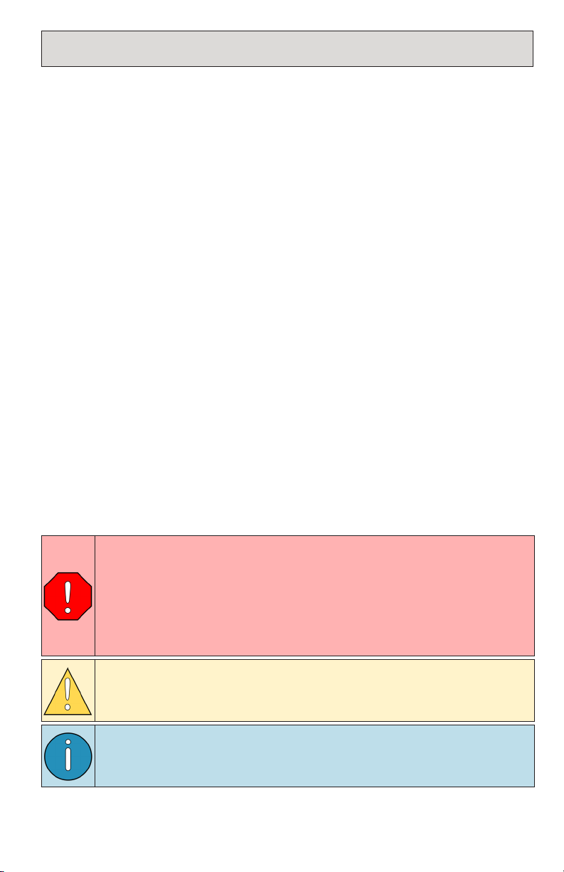
Safety Messages
This manual contains various warnings, cautions and notices that must be observed
to reduce the risk of personal injury during installation, service or repair and the
possibility that improper installation, service or repair may damage the equipment
or render it unsafe.
This symbol is used to call attention to instructions concerning
personal safety. Watch for this symbol; it points out important
safety precautions, it means, “Attention, become alert! Your
personal safety is involved”. Read the message that follows and
be aware of the possibility of personal injury or death. As it is
impossible to warn of every conceivable hazard, common sense and
industry standard safety practices must be observed.
This symbol is used to call attention to instructions on a specific
procedure that if not followed may damage or reduce the useful life
of the compressor or other equipment.
This symbol is used to call attention to additional instructions or
special emphasis on a specific procedure.
Safety
Other manuals for Underhood 70
3
This manual suits for next models
1
Table of contents
Other Vmac Air Compressor manuals

Vmac
Vmac V400015 User manual

Vmac
Vmac VR70 User manual

Vmac
Vmac UNDERHOOD 40 Series User manual

Vmac
Vmac VR70 Manual

Vmac
Vmac H600013 Installation instructions

Vmac
Vmac Underhood 70 User manual

Vmac
Vmac VR70 User manual

Vmac
Vmac VR70 User manual

Vmac
Vmac DM2A021 User manual

Vmac
Vmac UNDERHOOD 40 Series User manual

Vmac
Vmac VR70 User manual

Vmac
Vmac VR70 User manual

Vmac
Vmac PREDATAIR User manual

Vmac
Vmac V400007 User manual

Vmac
Vmac RAPTAIR-MF D600007 User manual

Vmac
Vmac VR70 User manual

Vmac
Vmac UNDERHOOD 40 Series User manual

Vmac
Vmac V400010 User manual

Vmac
Vmac V900113 User manual

Vmac
Vmac UNDERHOOD 40 Series User manual


