SMA Solar Technology AG SUNNY TRIPOWER 5000TL User manual


Legal Provisions
The information contained in these documents is property of SMA Solar Technology AG. Any
publication, whether in whole or in part, requires prior written approval by SMA Solar Technology
AG. Internal reproduction used solely for the purpose of product evaluation or other proper use is
allowed and does not require prior approval.
SMA Warranty
You can download the current warranty conditions from the Internet at www.SMA-Solar.com.
Trademarks
All trademarks are recognized, even if not explicitly identified as such. Missing designations do not
mean that a product or brand is not a registered trademark.
Modbus® is a registered trademark of SchneiderElectric and is licensed by the
ModbusOrganization,Inc.
QRCode is a registered trademark of DENSOWAVEINCORPORATED.
Phillips® and Pozidriv® are registered trademarks of PhillipsScrewCompany.
Torx® is a registered trademark of AcumentGlobalTechnologies,Inc.
SMA Solar Technology AG
Sonnenallee 1
34266 Niestetal
Germany
Tel. +49 561 9522-0
Fax +49 561 9522-100
www.SMA.de
Email: [email protected]
Status: 7/3/2017
Copyright © 2017 SMA Solar Technology AG. All rights reserved.
Legal Provisions SMA Solar Technology AG
Service Manual for InstallersSTP5-12TL-20-SG-en-132
www.renews.pro

Table of Contents
1 Information on this Document................................................. 4
1.1 Validity ............................................................................................... 4
1.2 Target Group ..................................................................................... 4
1.3 Symbols.............................................................................................. 4
1.4 Nomenclature.................................................................................... 5
2 Safety ........................................................................................ 6
2.1 Safety Information ............................................................................. 6
2.2 Disconnecting the Inverter from Voltage Sources............................ 7
3 Cleaning the Inverter ............................................................... 9
4 Troubleshooting........................................................................ 10
4.1 LED Signals ........................................................................................ 10
4.2 Event Messages................................................................................. 10
4.3 Error Messages.................................................................................. 11
5 Checking the PV System for Ground Faults ........................... 18
6 Checking the Function of the Varistors................................... 22
7 Replacing the Varistors............................................................ 24
8 Cleaning the Fans..................................................................... 25
9 Checking the Function of the Fans .......................................... 27
10 Recommissioning the Inverter................................................. 28
11 Decommissioning the Inverter................................................. 30
12 Spare Parts ............................................................................... 33
13 Contact ...................................................................................... 34
Table of Contents
SMA Solar Technology AG
Service Manual for Installers 3STP5-12TL-20-SG-en-13
www.renews.pro
1 Information on this Document
1.1 Validity
This document describes how to rectify certain errors and how to replace defective components.
This document supplements the documents that are enclosed with each product and does not
replace any locally applicable standards or directives. Read and observe all documents supplied
with the product.
This document is valid for the following device types from firmware version 2.56.03.R:
• STP 5000TL-20 (Sunny Tripower 5000TL)
• STP 6000TL-20 (Sunny Tripower 6000TL)
• STP 7000TL-20 (Sunny Tripower 7000TL)
• STP 8000TL-20 (Sunny Tripower 8000TL)
• STP 9000TL-20 (Sunny Tripower 9000TL)
• STP 10000TL-20 (Sunny Tripower 10000TL)
• STP 12000TL-20 (Sunny Tripower 12000TL)
1.2 Target Group
The tasks described in this document must only be performed by qualified persons. Qualified
persons must have the following skills:
• Knowledge of how an inverter works and is operated
• Training in how to deal with the dangers and risks associated with installing and using
electrical devices and installations
• Training in the installation and commissioning of electrical devices and installations
• Knowledge of the applicable standards and directives
• Knowledge of and compliance with this document and all safety information
1.3 Symbols
Symbol Explanation
Indicates a hazardous situation which, if not
avoided, will result in death or serious injury
Indicates a hazardous situation which, if not
avoided, can result in death or serious injury
Indicates a hazardous situation which, if not
avoided, can result in minor or moderate injury
Indicates a situation which, if not avoided, can
result in property damage
1Information on this Document SMA Solar Technology AG
Service Manual for InstallersSTP5-12TL-20-SG-en-134
www.renews.pro
Symbol Explanation
Information that is important for a specific topic
or goal, but is not safety-relevant
Indicates a requirement for meeting a specific
goal
Desired result
A problem that might occur
1.4 Nomenclature
Complete designation Designation in this document
SunnyTripower Inverter, product
ElectronicSolarSwitch ESS
SMA BLUETOOTH Wireless Technology BLUETOOTH
1 Information on this Document
SMA Solar Technology AG
Service Manual for Installers 5STP5-12TL-20-SG-en-13
www.renews.pro
2 Safety
2.1 Safety Information
This section contains safety information that must be observed at all times when working on or with
the product.
To prevent personal injury and property damage and to ensure long-term operation of the product,
read this section carefully and observe all safety information at all times.
Danger to life due to high voltages of the PV array
When exposed to sunlight, the PV array generates dangerous DC voltage, which is present in the
DC conductors and the live components of the inverter. Touching the DC conductors or the live
components can lead to lethal electric shocks. If you disconnect the DC connectors from the
inverter under load, an electric arc may occur leading to electric shock and burns.
• Do not touch non-insulated cable ends.
• Do not touch the DC conductors.
• Do not touch any live components of the inverter.
• Have the inverter mounted, installed and commissioned only by qualified persons with the
appropriate skills.
• If an error occurs, have it rectified by qualified persons only.
• Prior to performing any work on the inverter, disconnect it from all voltage sources as
described in this document.
Danger to life due to electric shock
Touching an ungrounded PV module or array frame can cause a lethal electric shock.
• Connect and ground the PV modules, array frame and electrically conductive surfaces so
that there is continuous conduction. Observe the applicable local regulations.
Risk of burns due to hot enclosure parts
Some parts of the enclosure can get hot during operation.
• During operation, do not touch any parts other than the enclosure lid of the inverter.
2Safety SMA Solar Technology AG
Service Manual for InstallersSTP5-12TL-20-SG-en-136
www.renews.pro
Damage to the seal of the enclosure lid in sub-zero conditions
If you open the enclosure lid in sub-zero conditions, the sealing of the enclosure lid can be
damaged. This can lead to moisture entering the inverter.
• Do not open the inverter at ambient temperatures lower than -5°C.
• If a layer of ice has formed on the seal of the enclosure lid in sub-zero conditions, remove it
prior to opening the inverter (e.g. by melting the ice with warm air). Observe the applicable
safety regulations.
Damage to the display or the type label due to the use of cleaning agents
• If the inverter is dirty, clean the enclosure, the enclosure lid, the type label, the display and
the LEDs with a damp cloth and clear water only.
2.2 Disconnecting the Inverter from Voltage Sources
Prior to performing any work on the inverter, always disconnect it from all voltage sources as
described in this section. Always adhere to the prescribed sequence.
Destruction of the measuring device due to overvoltage
• Only use measuring devices with a DC input voltage range of 1000V or higher.
Procedure:
1. Disconnect the circuit breaker from all three line conductors and secure against reconnection.
2. Remove the ESS.
3. Loosen two screws of the protective cover using an Allen key (AF5) and remove the protective
cover.
4. Use a current clamp to ensure that no current is present in the DC cables.
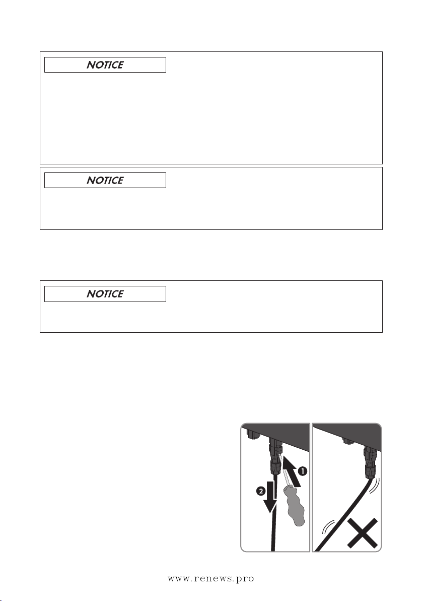
5. Release and remove all DC connectors. To do
this, insert a flat-blade screwdriver or an angled
screwdriver (blade width: 3.5mm) into one of
the side slots and pull the DC connectors straight
out. Do not pull on the cable.
2 Safety
SMA Solar Technology AG
Service Manual for Installers 7STP5-12TL-20-SG-en-13
www.renews.pro

6.
Danger to life due to high voltages
The capacitors in the inverter take five minutes to discharge.
• Wait five minutes before opening the enclosure lid.
7. Ensure that no voltage is present at the DC inputs of the inverter.
8. Unscrew all the screws of the enclosure lid using an Allen key (AF5) and remove the
enclosure lid.
9. Use an appropriate measuring device to ensure that no voltage is present at the AC
connecting terminal plate between L1 and N, L2 and N, and L3 and N. Insert the test probe
into each round opening of the terminal.
10. Use an appropriate measuring device to ensure that no voltage is present at the AC
connecting terminal plate between L1 and PE, L2 and PE, and L3 and PE. Insert the test
probe into each round opening of the terminal.
11. Ensure that no voltage is present between any terminal of the multifunction relay and PE of the
AC connecting terminal plate.
12.
Damage to the inverter due to electrostatic discharge
The internal components of the inverter can be irreparably damaged by electrostatic
discharge.
• Ground yourself before touching any component.
2Safety SMA Solar Technology AG
Service Manual for InstallersSTP5-12TL-20-SG-en-138
www.renews.pro
3 Cleaning the Inverter
Damage to the display or the type label due to the use of cleaning agents
• If the inverter is dirty, clean the enclosure, the enclosure lid, the type label, the display and
the LEDs with a damp cloth and clear water only.
3 Cleaning the Inverter
SMA Solar Technology AG
Service Manual for Installers 9STP5-12TL-20-SG-en-13
www.renews.pro
4 Troubleshooting
4.1 LED Signals
The LEDs indicate the operating state of the inverter.
LED Status Explanation
Green LED glowing Feed-in operation
If an event occurs during feed-in operation, an event mes-
sage will be shown on the display (for event messages see
the service manual at www.SMA-Solar.com).
flashing The conditions for feed-in operation are not yet met. As
soon as the conditions are met, the inverter will start feed-
in operation.
Red LED glowing Error
If an error occurs, the error message and the correspond-
ing event number will be shown in the display. The error
must be rectified by a qualified person (for troubleshoot-
ing, see the service manual at www.SMA-Solar.com).
Blue LED glowing For inverters including BLUETOOTH as standard equip-
ment: BLUETOOTH communication is activated.
4.2 Event Messages
Display message Cause
Update file OK The update file found is valid.
Grid parameter locked The parameters are locked and you cannot change them.
Update communication The inverter is updating the communication component.
Update main CPU The inverter is updating the inverter component.
Update Bluetooth The inverter updates the BLUETOOTH component.
Upd. language table The inverter is updating the language table.
Update completed The inverter has successfully completed the update.
Grid parameters unchanged The selected rotary switch position is not assigned or the grid param-
eters cannot be changed.
Inst. code valid The entered GridGuard code is valid. Protected parameters have
now been unlocked and you can adjust the parameters. The param-
eters will be automatically locked again after ten feed-in hours.
Self-test The self-test is in progress.
4Troubleshooting SMA Solar Technology AG
Service Manual for InstallersSTP5-12TL-20-SG-en-1310
www.renews.pro
4.3 Error Messages
Event number Display message, cause and corrective measures
101 to 103 Grid fault
The grid voltage or grid impedance at the connection point of the inverter is
too high. The inverter has disconnected from the utility grid.
Corrective measures:
• Check whether the grid voltage at the connection point of the inverter is
permanently in the permissible range.
If the grid voltage is outside the permissible range due to local grid
conditions, contact the grid operator. Ask the grid operator whether the
voltage can be adjusted at the feed-in point or request approval to
change the monitored operating limits.
If the grid voltage is permanently within the permissible range and this
message is still displayed, contact the SMAServiceLine.
202 to 203 Grid fault
The utility grid has been disconnected, the AC cable is damaged or the grid
voltage at the connection point of the inverter is too low. The inverter has dis-
connected from the utility grid.
Corrective measures:
• Make sure that the circuit breaker is switched on.
• Make sure that the AC cable is not damaged.
• Make sure that the AC cable is correctly connected.
• Check whether the grid voltage at the connection point of the inverter is
permanently in the permissible range.
If the grid voltage is outside the permissible range due to local grid
conditions, contact the grid operator. Ask the grid operator whether the
voltage can be adjusted at the feed-in point or request approval to
change the monitored operating limits.
If the grid voltage is permanently within the permissible range and this
message is still displayed, contact Service.
4 Troubleshooting
SMA Solar Technology AG
Service Manual for Installers 11STP5-12TL-20-SG-en-13
www.renews.pro
Event number Display message, cause and corrective measures
301 Grid fault
The ten-minute average value of the grid voltage is no longer within the per-
missible range. The grid voltage or grid impedance at the connection point is
too high. The inverter disconnects from the utility grid to maintain power qual-
ity.
Corrective measures:
• Check whether the grid voltage at the connection point of the inverter is
permanently in the permissible range.
If the grid voltage is outside the permissible range due to local grid
conditions, contact the grid operator. Ask the grid operator whether the
voltage can be adjusted at the feed-in point or request approval to
change the monitored operating limits.
If the grid voltage is permanently within the permissible range and this
message is still displayed, contact Service.
401 to 404 Grid fault
The inverter is no longer in grid-parallel operation. The inverter has stopped
feeding into the utility grid.
Corrective measures:
• Check the grid connection for significant short-term frequency fluctuations.
501 Grid fault
The power frequency is not within the permissible range. The inverter has dis-
connected from the utility grid.
Corrective measures:
• If possible, check the power frequency and observe how often
fluctuations occur.
If fluctuations occur frequently and this message is displayed often,
contact the grid operator and request approval to change the operating
parameters of the inverter.
If the grid operator gives his approval, discuss any changes to the
operating parameters with the Service.
601 Grid fault
The inverter has detected an excessively high proportion of direct current in
the grid current.
Corrective measures:
• Check the grid connection for direct current.
• If this message is displayed frequently, contact the grid operator and
check whether the monitoring threshold on the inverter can be raised.
4Troubleshooting SMA Solar Technology AG
Service Manual for InstallersSTP5-12TL-20-SG-en-1312
www.renews.pro
Event number Display message, cause and corrective measures
701 Frq. not permitted > Check parameter
The power frequency is not within the permissible range. The inverter has dis-
connected from the utility grid.
Corrective measures:
• If possible, check the power frequency and observe how often
fluctuations occur.
If fluctuations occur frequently and this message is displayed often,
contact the grid operator and request approval to change the operating
parameters of the inverter.
If the grid operator gives his approval, discuss any changes to the
operating parameters with the Service.
1302 Waiting for grid voltage > Installation failure grid connection > Check
grid and fuses
The inverter has detected an error in the AC cabling or the potential difference
between N and the grounding conductor in the installation is higher than
50V.
The inverter cannot connect to the utility grid.
Corrective measures:
• Ensure that the AC connection is correct (see operating manual of the
inverter).
• Ensure that there is no potential difference between N and the grounding
conductor in the building installation.
• Ensure that the country data set has been configured correctly. Check the
positions of the rotary switches A and B or select and check the
parameter for the country data set.
1501 Reconnection fault Utility grid
The changed country data set or the value of a parameter you have set does
not correspond to the local requirements. The inverter cannot connect to the
utility grid.
Corrective measures:
• Ensure that the country data set has been configured correctly. Check the
positions of the rotary switches A and B or select and check the
parameter for the country data set.
3302 to 3303 Unstable operation
There is not enough power at the DC input of the inverter for stable operation.
The inverter cannot connect to the utility grid.
Corrective measures:
• Ensure that the PV array is designed correctly.
4 Troubleshooting
SMA Solar Technology AG
Service Manual for Installers 13STP5-12TL-20-SG-en-13
www.renews.pro

Event number Display message, cause and corrective measures
3401 to 3402 DC overvoltage > Disconnect generator
Overvoltage at the DC input. This can destroy the inverter.
Corrective measures:
• Immediately disconnect the inverter from all voltage sources (see
Section2.2, page7).
• Check whether the DC voltage is below the maximum input voltage of
the inverter. If the DC voltage is below the maximum input voltage of the
inverter, reconnect the DC connectors to the inverter.
• If the DC voltage is above the maximum input voltage of the inverter,
ensure that the PV array has been correctly rated or contact the installer
of the PV array.
• If this message is repeated frequently, contact the Service.
3501 Insulation resist. > Check generator
The inverter has detected a ground fault in the PV array.
Corrective measures:
• Check the PV system for ground faults (see Section5, page18).
3601 High discharge curr. > Check generator
The leakage current from the inverter and the PV array is too high. There is a
ground fault, a residual current or a malfunction.
The inverter interrupts feed-in operation immediately after exceeding a thresh-
old and then automatically reconnects to the utility grid.
Corrective measures:
• Check the PV system for ground faults (see Section5, page18).
3701 Resid.curr.too.high > Check generator
The inverter has detected a residual current due to temporary grounding of the
PV array.
Corrective measures:
• Check the PV system for ground faults (see Section5, page18).
3801 to 3802 DC overcurrent > Check generator
Overcurrent at the DC input. The inverter briefly interrupts feed-in operation.
Corrective measures:
• If this message is displayed frequently, ensure that the PV array has been
correctly rated and wired.
4Troubleshooting SMA Solar Technology AG
Service Manual for InstallersSTP5-12TL-20-SG-en-1314
www.renews.pro
Event number Display message, cause and corrective measures
3901 to 3902 Waiting for DC start conditions > Start cond. not met
The feed-in conditions for the utility grid are not yet fulfilled.
Corrective measures:
• Wait for higher irradiation.
• If this message is displayed frequently in the morning, increase the
voltage limit for starting grid feed-in. Change the parameter Critical
voltage to start feed-in.
• If this message is displayed frequently with medium irradiation, ensure
that the PV array is correctly rated.
6001 to 6438 Self diagnosis > Interference device
The cause must be determined by the Service.
Corrective measures:
• Contact the Service.
6501 to 6509 Self-diagnosis > Overtemperature
The inverter has switched off due to excessive temperature.
Corrective measures:
• Clean the fans (see Section8, page25).
• Ensure that the inverter has sufficient ventilation.
6511 Overtemperature
The inverter has switched off due to excessive temperature.
Corrective measures:
• Clean the fans (see Section8, page25).
• Ensure that the inverter has sufficient ventilation.
6603 to 6604 Self-diagnosis > Overload
The cause must be determined by the Service.
Corrective measures:
• Contact the Service.
6801 to 6802 Self-diagnosis > Input A defective
The cause must be determined by the Service.
Corrective measures:
• Contact the Service.
6901 to 6902 Self-diagnosis > Input B defective
The cause must be determined by the Service.
Corrective measures:
• Contact the Service.
4 Troubleshooting
SMA Solar Technology AG
Service Manual for Installers 15STP5-12TL-20-SG-en-13
www.renews.pro
Event number Display message, cause and corrective measures
7001 to 7002 Sensor fault fan permanently on
The cause must be determined by the Service.
Corrective measures:
• Contact the Service.
7401 Varistor defective
At least one of the thermally monitored varistors is defective.
Corrective measures:
• Check the function of the varistors (see Section6, page22).
7701 to 7703 Self diagnosis > Interference device
The cause must be determined by the Service.
Corrective measures:
• Contact the Service.
8001 Derating occurred
The inverter has reduced its power output for more than ten minutes due to ex-
cessive temperature.
Corrective measures:
• If this message is displayed frequently, clean the fans (see Section8,
page25).
• Ensure that the inverter has sufficient ventilation.
8101 to 8104 Comm. disturbed
The cause must be determined by the Service.
Corrective measures:
• Contact the Service.
8801 to 8803 No display
This error message can have three causes, but the inverter continues to feed
into the utility grid.
The ambient temperature is lower than -25°C. The display switched off for
reasons of protection.
The inverter cannot identify the display type.
No display is connected to the inverter or the connection is defective.
Corrective measures:
• If the display switched off due to the ambient temperature being too low,
wait until the ambient temperature is above -25°C.
• If the ambient temperature is above -25°C, contact the Service.
4Troubleshooting SMA Solar Technology AG
Service Manual for InstallersSTP5-12TL-20-SG-en-1316
www.renews.pro
Event number Display message, cause and corrective measures
9002 Inst. code invalid
The GridGuard code entered is incorrect. The operating parameters are still
protected and cannot be changed.
Corrective measures:
• Enter the correct GridGuard code.
9003 Grid parameter locked
The parameters are now locked. You cannot change the parameters.
Corrective measures:
• Unlock the parameters with the GridGuard code.
4 Troubleshooting
SMA Solar Technology AG
Service Manual for Installers 17STP5-12TL-20-SG-en-13
www.renews.pro
5 Checking the PV System for Ground Faults
If the inverter displays the event numbers 3501, 3601 or 3701, there could be a ground fault. The
electrical insulation from the PV system to ground is defective or insufficient.
Danger to life due to electric shock
In the event of a ground fault, high voltages can be present.
• Touch the cables of the PV array on the insulation only.
• Do not touch any parts of the substructure or frame of the PV array.
• Do not connect PV strings with ground faults to the inverter.
Destruction of the measuring device due to overvoltage
• Only use measuring devices with a DC input voltage range of 1000V or higher.
Procedure:
In order to check the PV system for ground faults, perform the following actions in the prescribed
order. The exact procedure is described in the following sections.
• Check the PV system for ground faults by measuring the voltage.
• If the voltage measurement was not successful, check the PV system via insulation resistance
measurement for ground faults.
Test by Measuring the Voltage
Proceed as follows to check each string in the PV system for ground faults.
Procedure:
1.
Danger to life due to high voltages
• Disconnect the inverter from all voltage sources (see Section2.2, page7).
2. Measure the voltages:
• Measure the voltage between the positive terminal and the ground potential (PE).
• Measure the voltage between the negative terminal and the ground potential (PE).
• Measure the voltage between the positive and negative terminals.
If the following results are present at the same time, there is a ground fault in the PV
system:
☑ All measured voltages are stable.
☑ The sum of the two voltages to ground potential is approximately equal to the
voltage between the positive and negative terminals.
5Checking the PV System for Ground Faults SMA Solar Technology AG
Service Manual for InstallersSTP5-12TL-20-SG-en-1318
www.renews.pro

• If a ground fault is present, determine the location of the ground fault via the ratio of the
two measured voltages and eliminate the ground fault.
Example: Location of the ground fault
The example shows a ground fault between the second and third PV module.
3. If a definite ground fault cannot be measured and the message is still displayed, measure the
insulation resistance.
4. Reconnect the strings without ground faults to the inverter and recommission the inverter.
Test by Measuring the Insulation Resistance
If the voltage measurement does not provide sufficient evidence of a ground fault, the insulation
resistance measurement can provide more exact results.
Figure 1: Schematic diagram of the measurement
5 Checking the PV System for Ground Faults
SMA Solar Technology AG
Service Manual for Installers 19STP5-12TL-20-SG-en-13
www.renews.pro
Calculating the insulation resistance
The expected total resistance of the PV system or of an individual string can be calculated
using the following formula:
total
The exact insulation resistance of a PV module can be obtained from the module manufacturer
or the datasheet.
For the resistance of a PV module an average value can be assumed: for thin-film PV modules
approximately 40MOhm and for polycrystalline and monocrystalline PV modules
approximately50MOhm per PV module (for further information on calculating the insulation
resistance see the Technical Information "Insulation Resistance (Riso) of Non-Galvanically
Isolated PV Systems" at www.SMA-Solar.com).
Required devices:
☐ Suitable device for safe disconnection and short-circuiting
☐ Measuring device for insulation resistance
Device required for safe disconnection and short-circuiting of the PV array
The insulation resistance can only be measured with a suitable device for safe disconnection
and short-circuiting of the PV array. If no suitable device is available, the insulation
measurement must not be carried out.
Procedure:
1. Calculate the expected insulation resistance per string.
2.
Danger to life due to high voltages
• Disconnect the inverter from all voltage sources (see Section2.2, page7).
3. Install the short circuit device.
4. Connect the measuring device for insulation resistance.
5. Short-circuit the first string.
6. Set the test voltage. The test voltage should be as close as possible to the maximum system
voltage of the PV modules but must not exceed it (see datasheet of the PV modules).
7. Measure the insulation resistance.
8. Eliminate the short circuit.
9. Measure the remaining strings in the same manner.
☑ If the insulation resistance of a string deviates considerably from the theoretically
calculated value, there is a ground fault present in that string.
10. Reconnect to the inverter only those strings from which the ground fault has been eliminated.
11. Reconnect all other strings to the inverter.
5Checking the PV System for Ground Faults SMA Solar Technology AG
Service Manual for InstallersSTP5-12TL-20-SG-en-1320
www.renews.pro
This manual suits for next models
6
Table of contents
Other SMA Solar Technology AG Inverter manuals


Popular Inverter manuals by other brands


Delta
Delta M70A 260 Installation and operation manual

Centech
Centech 60601 Owner's manual & safety instructions

Power Drive
Power Drive 1500 owner's guide

FRONIUS
FRONIUS Tauro quick start guide

Delta
Delta M125HV 110 Installation and operation manual

Sun Power
Sun Power SPR-X22-360-COM Safety and installation instructions

FRONIUS
FRONIUS Primo 3.8-1 208-240 operating instructions

MQ Power
MQ Power WHISPERWATT DCA-36SPX Operation and parts manual

Green Power
Green Power 600G Installation instructions & user manual

XPower
XPower 1500 owner's guide

MQ Power
MQ Power WHISPERWELD DAW-500S Parts and operation manual

Tripp Lite
Tripp Lite APS 612 owner's manual