Green Power 600G Manual

Installation Instructions / User Manual
Microinverter connected to the grid
photovoltaic and type designations

Important safety instructions................................................................... 1-3
Safety instructions
Radio interference statement for communications
Symbols to replace words on equipment, displays and instructions
Introduction to the microinverter system............................................ 3-5
How microwaves maximize energy production from PV installations
Less unreliable microinverters
Easy installation
Introduction to the microinverter........................................................... 5
Installation of a microinverter system................................................... 6-9
Additional PV installation components
Required parts and tools
Installation procedures
Microinverter System User Manual......................................................... 9-10
Troubleshooting............................................................................................. 10-12
Status indicator and error reporting
Troubleshooting a malfunctioning microinverter
Indicator............................................................................................................ 13
Microinverter replacement........................................................................ 13
Technical data................................................................................................ 13-15
Datasheets
MPL MicroPV1300-ZB/MPLMicroPV1300-PLC
MPL MicroPV600-ZB/MPLMicroPV600-PLC
Wiring diagram.............................................................................................. 16-21
Example connection diagrams

Important safety instructions
This manual contains important information that must be followed during
installation and maintenance of the grid-connected photovoltaic inverter
(microinverter). To reduce the risk of electric shock and ensure safe installation
and operation of the microinverter, the following symbols appear hroughout
this document to indicate to hazardous conditions and important safety
instructions.
Specifications are subject to change without notice - Make sure you are using
the latest update found on the manufacturer’s website
WARNING:
This indicates a situation where failure to follow instructions could result in serio-
us equipment failure or danger to personnel, if not used properly. Use extreme
caution when performing this task.
WARNING:
This indicates information important to the optimized operation of the
microinverter. Follow these instructions.
Safety instructions
•DO NOT disconnect the photovoltaic module from the microinverter without
first disconnecting the mains power
• Only qualified professionals should install or replace microinverters
• Perform all electrical installations in accordance with local electrical codes
• Read all instructions and warning signs in the technical documentation before
installing or using the Microinverter.
• Note that the microinverter body is a heat sink and may reach a temperature of
80°C. To reduce the risk of burns, do not touch the microinverter
•DO NOT attempt to repair the Microinverter. Contact customer service to obtain
the RAM number and begin the replacement process. Damaging or opening the
microinverter will void the warranty.
-1-

• Recommendation!
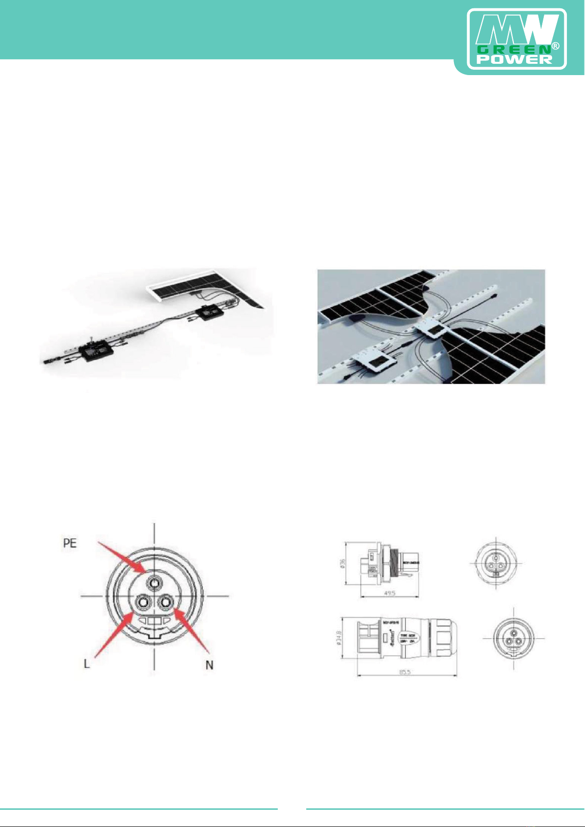
The external protective ground wire is connected to the protective ground ter-
minal of the inverter via the AC connector.
When connecting, connect the AC connector first to ensure that the inverter is
grounded, and then make the DC connection.
When disconnecting, disconnect the AC power by opening the branch circuit
breaker first, but keep the protective ground wire in the branch circuit breaker,
connect to the inverter, and then disconnect the DC inputs.
• Under no circumstances should the DC input be connected when the AC con-
nector is disconnected.
• Install isolating switching devices on the AC side of the inverter.
Radio Interference Statement
CE EMC Compliance: This equipment may comply with CE EMC, which are de-
signed to protect against harmful interference in a residential installation. This
equipment may emit radio frequency energy which can cause harmful interfe-
rence to radio communications if not installed and used in accordance with the
instructions. But there is no guarantee that interference will not occur in a par-
ticular installation. If this equipment does cause harmful interference to radio or
television reception, the following measures may solve the problems:
A) Reposition the receiving antenna and keep it away from the equipment
B) Consult the dealer or an experienced radio/TV technician for help
Changes or modifications not expressly approved by the party responsible for compliance could
void the user’s authority to operate the equipment.
Energy Monitoring and Analysis (EMA) systems software analyzes and reports the performance
of each module based on real-time data collected by the Energy Collection Device (ECD) ga-
teway. EMA immediately detects any performance issues in the array, indicating the location
and nature of the problem and providing precise maintenance guidance, all in a user-friendly
graphical interface. Communication between the inverter and the ECD can be affected by
signal „noise” from a nearby electrical device, the distance between the inverters and the ECD,
the number of inverters supported, and other factors, so sometimes the ECD experiences a
random loss of signal or data, this is not a problem or a fault. If the ECD is not communicating
with the EMA database at all, please contact technical support.
-2-

Symbols replace words on equipment, displays or in instructions
May be an OEM trademark.
Caution risk of electric shock.
Caution hot surface.
Symbol for the marking of electrical and electronic equipment in accordance with
Directive 2009/96/EC. Indicates that the appliance, its accessories and packaging must
not be disposed of as unsorted municipal waste and must be collected separately at the
end of their useful life. Follow local ordinances or regulations for disposal or contact the
manufacturer’s authorized r
epresentative for information on end-of-life disposal.
The solar inverter bears the CE mark to verify that the device complies with the Europe-
an Low Voltage and EMC Directives.
Refer to the instruction manual.
Wykwali-
fikowany
personel
A person who is adequately informed or supervised by a qualified electrician so that
risks can be perceived and hazards posed by electricity can be avoided. For the purpose
of information security in the scope of this manual,
a „qualified person” is a person who is familiar with safety, refrigeration
system, and EMC requirements and is authorized to energize, ground, and mark system
equipment and circuits in accordance with established safety procedures. The inverter
and terminal system must only be started up and operated by qualified personnel.
Introduction to the microinverter system
The microinverter is used in interactive network-related applications and con-
sists of three key components:
- Microinverter
- Energy Collection Device (ECD) + WIFI Plug
- Web-based Energy Monitor and Analysis (EMA)
-3-

MPL MicroPV 600-ZB or MPL Micro PV 600-PLC
MPL MicroPV 1300-ZB or MPL Micro PV 1300-PLC
This integrated system improves safety; maximizes solar energy use; increases
system reliability; and simplifies the design, installation, maintenance, and ma-
nagement of a photovoltaic system.
-4-

Microinverters maximize PV energy production
Each photovoltaic module has individual maximum peak power tracking (MPPT)
controls. This ensures that the maximum power produced is independent of the
performance of other PV modules in the installation.
When photovoltaic modules are affected by shadow, dust, orientation or any
situation in which one module underperforms compared to other units, the
microinverter ensures the highest efficiency, maximizing the performance of
each module.
More reliable than series inverters.
Distributed microinverter system ensures that there is no single failure affecting
the entire system. The inverter housing is designed for outdoor installation and
complies with IP67 protection class.
Easy to install
Individual photovoltaic modules can be installed in any combination, number,
orientation and different types. The ground wire (PE) of the AC cable is connec-
ted to the housing inside the microinverter, potentially eliminating the use of a
ground wire (check local ordinance).
The MPL MicroPV Gate energy storage device (MECD) is installed by plugging it
into any wall outlet and providing a broadband Ethernet connection to a router
or modem. Once installed and set up (see ECD manual), the entire network of
microinverters automatically reports to the Solarman web server. The software
displays performance trends, abnormal situation information and controls sys-
tem shutdown when needed.
Introduction to the microinverter
Microinverters connect to a single-phase grid, and can also use multiple
microinverters in a single-phase grid to achieve a three-phase grid, and work
with most 60 and 72 cell PV modules. Please refer to the technical data page
(16~21) of this manual for more information.
Model
number AC system ModulePV Max. # per
branch
600G
50/60Hz, 230V 60,72 cell
8 for 25A circuit
breaker
1300G 4 for 25A circuit
braker
-5-

A PV system using microinverters is simple to install. Each microinverter can be
easily mounted on a mounting system directly under the photovoltaic modules.
DC wires connect the PV module directly to the microinverter which eliminates
the presence of high DC voltage.
Installation MUST comply with local and technical codes.
Microinverter installation
WARNING Perform all electrical installations in accordance with local codes.
WARNING Only qualified professionals should install/replace microinverters.
WARNING Before installing or using the microinverter, read all instructions and warnings
in the technical documentation and on the microinverter itself.
WARNING Please note that there is a risk of electric shock when installing this device.
WARNING Do not touch any live parts on the system, including the photovoltaic system,
when the system has been connected to the mains.
ATTENTION We strongly recommend installing surge protection devices for the
photovoltaic AC switchgear.
Additional installation components
• Male and female AC connectors (sold separately)
• End caps (sold separately)
•
Required parts and tools
In addition to the photovoltaic kit and associated hardware, you will need the
following items:
• AC junction box
• Mounting hardware suitable for the mounting system
• Sockets and wrenches for mounting the equipment
• Continuous ground wire and grounding washers
• Phillips screwdriver
• Torque wrench
-6-

Installation Procedures
Step 1 - Install the AC splitter box
a) Install the appropriate junction box in a suitable location (called a hub) near
the microinverter chains.
b) Connect the end of the AC cable to the junction box with a suitable choke or
connector.
c) Connect the AC wires to: L-Red; N-Black; PE-Yellow-Green.
d) Connect the AC junction box (hub) to the power connection point.
WARNING: Wiring color code may vary according to local codes, check all wiring
before connecting to the AC cable to make sure they match. Incorrect wiring
can irreparably damage the microinverters, this problem is not covered under
warranty.
Step 2 - Mount the microinverter on the mounting structure or frame of the
photovoltaic module.
a) Mark the position of the microinverter on the structure in relation to the pho-
tovoltaic module junction box or other components.
b) Mount one microinverter at each location using the equipment recommen-
ded by the mounting system supplier.
Mounting
MPL MicroPV 600-ZB
MPL MicroPV 600-PLC
MPL MicroPV 600-Wifi
Mounting
MPL MicroPV 1300-ZB
MPL MicroPV 1300-PLC
MPL MicroPV 1300-Wifi
-7-

WARNING: Before installing any of the microinverters, check that the voltage at
the connection point matches the voltage rating on the microinverter label.
WARNING: Do not place inverters (including DC and AC connectors) in areas
exposed to sun, rain, or snow. Maintain spacing between modules. Leave at
least 3/4’ (1.5cm) between the roof and the bottom of the microinverter to allow
adequate airflow.
Step 3 - Connect serial microinverters, photovoltaic modules to each DC input
600-ZB/PLC series connection in one branch 1300-ZB/PLC series connection in one branch
a) Check the microinverter technical data page (page 18) for the maximum
allowable number of microinverters in each chain.
b) Connect the male AC connector of the microinverter to the female connector
to connect them
WARNING: Do not exceed the maximum number of microinverters on the AC
branch circuit as shown on page 7 of this manual.
-8-

Step 4 - Install a protective cap for the AC cable at the end of the AC cable.
Step 5 - Connect microinverters to photovoltaic modules.
WARNING: When the DC cables are connected the microinverter should
immediately flash one quick red and three times the green LED. This will
happen as soon as the cables are connected which will show that the
microinverter is working properly.
This entire check function will start and stop within 5 seconds of connecting the
unit, so keep an eye out for these lights when connecting the DC cables.
Microinverter System User Manual
To operate a microinverter PV system:
1 Turn on the AC breaker on each AC circuit of the microinverter.
2. turn on the main AC breaker from the grid. Your system will begin generating
power after a minute of waiting.
-9-

3. The devices should start blinking red one minute after the AC power switch
is turned on. The blue LED then flashes. This means, This means they are gene-
rating power normally, a faster flashing blue LED means more power is being
generated.
4. connect the ECD and follow the instructions according to the ECD
5. the Microinverters will begin to send power output data through the power
line to the ECD. The time required for all microinverters in the system to report
to the ECD will vary depending on the number of microinverters in the system.
You can verify the correct operation of the microinverters using the ECD.
Refer to the ECD installation and operation manual for more information.
WARNING: When AC power is applied, approximately 0.1 A of current and 25VA
(W) of power can be measured for each microinverter using a meter.
This current and power are reactive. The inverters are NOT operating. After more
than 60 seconds, the inverters will begin to operate
Troubleshooting
Qualified personnel can use the following steps if the photovoltaic system is not
working properly:
Status indications and error reporting
Activate the LED
One minute after the first DC connection to the microinverter, one short red
blink indicates a successful startup sequence of the microinverter,
two or more short red flashes indicate a failure during microinverter setup.
LED operation
Blinks slowly in blue - low power generation
Flashing fast blue - high output
Flashing red - no power output
Red blinks twice - low AC voltage or high voltage
Red blinks three times - mains failure
-10-

GFDI error
A quadruple red LED indicates that the microinverter has detected a ground
fault device interrupt (GFDI) error in the photovoltaic system.
Unless the GFDI error is corrected, the LED will flash four times
Other Faults
All other faults are reported to the ECD. A list of additional faults and
troubleshooting procedures can be found in the in the ECD installation and
operation manual.
WARNING: Never disconnect DC wire connectors under load. Make sure that no
current is flowing in the DC leads before disconnecting. An opaque cover can be
used to cover the module before disconnecting the module.
Troubleshooting a non-functioning microinverter
There are two possible general problems:
a) The microinverter itself may be having problems
b) The microinverter itself is working fine, but has ECD communication pro-
blems. The following items address microinverter problems, not communication
problems (addressed in the ECD manual)
A quick way to determine if it is a microinverter or ECD communication
problem:
1. diagnosis from the microinverter side: Red light - either flashing or continuous
light on the microinverter, or no light at all.
No light or red light means there is definitely a problem with the microinverter.
Diagnosing the microinverter trouble
a) No data display: This is probably a communication problem and not a micro-
inverter problem.
b) Problems with erroneous display: Data is displayed for some time and then
no data is displayed: most likely a communication problem.
c) 0 watts or 2 watts: Likely a microinverter problem
d) Incorrect data display that is not coordinated with data displayed from other
devices: most likely a microinverter problem
-11-

To troubleshoot a non-functioning mikiroinverter, perform the following steps in
order:
1. Check that the mains voltage and frequency are within the ranges shown in
the Technical Data section of this manual.
2. Check the connection to the power grid. Check that the line voltage is present
at the inverter in question by removing the AC current and then the DC current.
Never disconnect the DC leads while the microinverter is generating power.
Reconnect the DC module connectors and watch for three short LED flashes.
3. Check the AC branch circuit connection between all microinverters.
4. Verify that each inverter is energized as described in the previous step.
5. Verify that any AC circuit breaker is functioning properly and is closed.
6. Check that the DC voltage of the photovoltaic module is within the allowable
range indicated in the technical data in this manual.
7. If the problem persists, contact Customer Service.
WARNING: Do not attempt to repair the microinverter. If troubleshooting me-
thods fail, contact Technical Support.
-12-

No maintenance is required.
Maintenance
Follow the procedure to replace a defective Microchip
1. Disconnect the microinverter from the photovoltaic module in the order
shown below:
1.1. Disconnect the AC by turning off the branch circuit breaker.
1.2. Disconnect the AC connector of the microinverter.
1.3. Cover the module with the opaque cover.
1.4. Disconnect the DC cable connectors of the photovoltaic module from the
microinverter.
1.5. remove the microinverter from the photovoltaic cabinet.
2. Remove the opaque cover, install the replacement microinverter in the cabi-
net. Remember to watch the flashing LED light as soon as the new microinver-
ter is connected to the DC cables.
3. Connect the AC cable of the replacement microinverter.
4. Close the overcurrent circuit breaker and check the operation of the replace-
ment microinverter.
Microinverter replacement
Technical data
WARNING: Make sure that the voltage and current specifications of the photo-
voltaic module match those of the microinverter.
Refer to the datasheet or user manual.
WARNING: Match the DC operating voltage range of the photovoltaic module
with the allowable input voltage range of the microinverter.
WARNING: The maximum open circuit voltage of the photovoltaic module must
not exceed the specified maximum input voltage of the inverter.
-13-

Data sheet for microinverter 600W
MPL MicroPV 600-ZB / MPL MicroPV 600-PLC
Input data (DC)
Recommended input power
(STC) 210 ~ 400W (2 pcs.)
Maximum voltage 60V
MPPT voltage range 25 ~ 55V
DC operating voltage range 20 ~ 60V
Maximum short-circuit current 13A
Nominal input current 10,4 x2
Output data (AC)
Maximum output power 600W
Rated power 500W
Nominal/Max. output current 2,17A / 2,68A
Nominal voltage / range 184 ~ 265V
Nominal frequency / range 50Hz / 47,5 ~ 51,5Hz
Extended frequency / range 50Hz / 45 ~ 55Hz
Power factor >0,90
Maximum number in line 8
Efficiency
CEC weighted efficiency 95%
Maximum inverter capacity 96,5%
Static MPPT performance 99%
Energy consumption at night 50mW
Mechanical data
Ambient temperature range -40°C ~ +65°C
Dimensions (W x H x D) 188 x 164 x 29mm
Weight 2,2kg
Cooling Natural convection - no fans
Degree of protection for housing Outdoor-NEMA6 / IP67
Properties
Compliance Compatible with 60 ~ 82 photovoltaic cells
Communication Power line / PLC / Zigbi / WiFi
Compliance UL1741, VDE0126, VDE4105, IEC62109, CE, EU50548
Warranty 12 years
-14-

Data sheet for microinverter 1300W
MPL MicroPV 1300-ZB / MPL MicroPV 1300-PLC
Input data (DC)
Recommended input power
(STC) 210 ~ 400W (4 pcs.)
Maximum voltage 60V
MPPT voltage range 25 ~ 55V
DC operating voltage range 20 ~ 60V
Maximum short-circuit current 13A
Nominal input current 10,4 x4
Output data (AC)
Maximum output power 1300W
Rated power 1200W
Nominal/Max. output current 4,34A / 5,45A
Nominal voltage / range 184 ~ 265V
Nominal frequency / range 50Hz / 47,5 ~ 51,5Hz
Extended frequency / range 50Hz / 45 ~ 55Hz
Power factor >0,95
Maximum number in line 48
Efficiency
CEC weighted efficiency 95%
Maximum inverter capacity 96,5%
Static MPPT performance 99%
Energy consumption at night 50mW
Mechanical data
Ambient temperature range -40°C ~ +65°C
Dimensions (W x H x D) 450 x 455 x 35mm
Weight 6,5kg
Cooling Natural convection - no fans
Degree of protection for housing Outdoor-NEMA6 / IP67
Properties
Compliance Compatible with 60 ~ 82 photovoltaic cells
Communication Power line / DLC / Zigbee / WiFi
Compliance UL1741, VDE0216, VDE4105, IEC62109, CE, EU50548
Warranty 12 years
-15-

Connection diagram
MPL MicroPV 600-ZB / MPL MicroPV 600-PLC
Example of three-phase connection diagram
BLACK L2
RED L1
YELLOW NEUTRAL
Counter
Concentrator
Grounding
Ethernet cable connected
to broadband router
Annotations: If you are using our zigbee type, you only need
one ECD. If you are using our PCL type, you should install three
ECDs per phase.
AC distribution
board
-16-

Connection diagram
MPL MicroPV 600-ZB / MPL MicroPV 600-PLC
Example of one-phase connection diagram
BLACK L2
RED L1
YELLOW NEUTRAL
Counter
Concentrator
Grounding
AC distribution
board
MPL MicroPV Gate
WiFi plug
ethernet cable
connect to the router
broadband
-17-

Connection diagram
Example of three-phase connection diagram for Europe
ATTENTION: If you are using our zigbee type, you only need one ECD. If you are using
our PLC type, you need to install three ECDs in each phase.
BLACK L2
RED L1
YELLOW NEUTRAL
Counter
Concentrator
Grounding
AC distribution
board
MPL MicroPV Gate
WiFi plug
ethernet cable
connect to the router
broadband
WiFi plug
-18-
This manual suits for next models
1
Table of contents
Other Green Power Inverter manuals
Popular Inverter manuals by other brands

Champion
Champion 100155 Owner's manual & operating instructions

Westerbeke
Westerbeke 3.5KW SBCG-60Hz Operator's manual

Desa
Desa RN30E-CAN OWNER'S OPERATION AND INSTALLATION MANUAL

Kyocera
Kyocera KD135GX-LPU installation manual

Toshiba
Toshiba TOSVERT VF-S15 series Quick start manual

Victron energy
Victron energy Quattro 12/3000/120-50/50 230V manual

Xantrex
Xantrex GT5.0-NA owner's manual

GW Instek
GW Instek AFG-3021 quick start guide

Hitachi
Hitachi J100-E2 SERIES Service manual

Del ozone
Del ozone CDS-16 Installation & operation manual

Generac Power Systems
Generac Power Systems 00919-0 owner's manual

Kipp & Zonen
Kipp & Zonen SOLYS 2 instruction manual