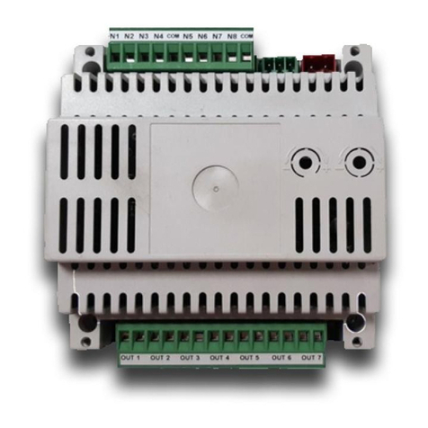
Small Box Chameleon 2.0 User manual

Chameleon 2.0 Installation Guide
www. Smallboxenergy.com Phone: 480-253-3999 Option 4
1
Delivering the Ultimate Energy Management Solution
for Restaurants and Convenience Stores

Chameleon 2.0 Installation Guide
www. Smallboxenergy.com Phone: 480-253-3999 Option 4
2
Table of Contents
SBE SUPPORT CONTACTS.........................................................................................................................4
Web Access .........................................................................................................................................4
URLS.................................................................................................................................................... 4
SYSTEM OVERVIEW ................................................................................................................................. 5
PRE-INSTALL SURVEY ............................................................................................................................... 6
SBE Installation app ................................................................................................................................. 7
iOS:......................................................................................................................................................7
Android: ..............................................................................................................................................8
INSTALLATION PROCESS ........................................................................................................................ 10
Web Server........................................................................................................................................ 10
Cradle Point (Optional) ...................................................................................................................... 10
Ethernet Switch (Optional) ................................................................................................................ 10
Plug Strip (Optional) .......................................................................................................................... 10
Gesy Temperature Monitoring Receiver - 2.0..................................................................................... 10
Refrigeration Control............................................................................................................................. 11
Walk-in Freezer ..................................................................................................................................... 11
Cut over Cooling................................................................................................................................ 11
Cut over Heating................................................................................................................................ 11
Installing temperature probes ........................................................................................................... 12
Connecting Communication to Controller.......................................................................................... 12
Configuration of the Controller.......................................................................................................... 12
Temperature set point................................................................................................................... 13
Set defrost type ............................................................................................................................. 13
Scheduled defrost.......................................................................................................................... 13
Defrost termination set point ........................................................................................................ 13
Modbus addressing ....................................................................................................................... 13
Final Step....................................................................................................................................... 13
Walk-in Cooler....................................................................................................................................... 13
Cut over Cooling................................................................................................................................ 13
Installing temperature probes ........................................................................................................... 15
Connecting Communication to Controller.......................................................................................... 15

Chameleon 2.0 Installation Guide
www. Smallboxenergy.com Phone: 480-253-3999 Option 4
3
Configuration of the Controller.......................................................................................................... 15
Temperature set point................................................................................................................... 16
Set defrost type ............................................................................................................................. 16
Scheduled defrost.......................................................................................................................... 16
Defrost termination set point ........................................................................................................ 16
Modbus addressing ....................................................................................................................... 16
Final Step....................................................................................................................................... 16
Lighting Control Panel ........................................................................................................................... 18
Locate current lighting control........................................................................................................... 18
Mount lighting panel ......................................................................................................................... 18
Connect 110v to power lighting control ............................................................................................. 18
Connect Modbus communication ...................................................................................................... 18
Cutting over the lighting .................................................................................................................... 18
Power Meter ......................................................................................................................................... 19
Locating main service feeders............................................................................................................ 19
Installing the CT’s or Current transducers .......................................................................................... 19
Split core CT’s ................................................................................................................................ 19
Rope CT’s....................................................................................................................................... 19
Connecting CT’s to Meter .................................................................................................................. 19
Installing and powering the meter ..................................................................................................... 19
Communication ................................................................................................................................. 20
Testing .............................................................................................................................................. 20
Thermostats .......................................................................................................................................... 20
Identify wires in original thermostat .................................................................................................. 20
Connecting SBE Thermostat............................................................................................................... 20
Configuration of thermostats............................................................................................................. 21
Set time ......................................................................................................................................... 21
Change schedules to “N” ............................................................................................................... 21
Change sensors to out ................................................................................................................... 21
Set cooling and heating stages ....................................................................................................... 21
Disable Filter Status ....................................................................................................................... 21
Return to home screen .................................................................................................................. 21
Calibrate room/discharge sensors.................................................................................................. 21

Chameleon 2.0 Installation Guide
www. Smallboxenergy.com Phone: 480-253-3999 Option 4
4
Food Safety ........................................................................................................................................... 22
Mounting the Receiver ...................................................................................................................... 22
Wireless Temperature Sensors .......................................................................................................... 22
Connecting to webserver....................................................................................................................... 22
Commissioning Devices to system ......................................................................................................... 23
Accessing the webserver from laptop ................................................................................................ 23
Adding Modbus Devices to System .................................................................................................... 23
Adding ZigBee Thermostats to System ............................................................................................... 23
Checkout ............................................................................................................................................... 23
Optional Devices: Occupancy Sensor ..................................................................................................... 24
Optional Devices: Water heater temperature sensor............................................................................. 27
Optional Devices: Photocell, This would be for extra control of exterior lighting.................................... 28
SBE SUPPORT CONTACTS
• Jim Parker – Director of Deployment – 1st contact for all install support
480-297-5240 or jparker@smallboxenergy.com
• Jake B Parsons – Technical Support Manager – Jim’s back-up for install support
480-568-8675 or jparsons@smallboxenergy.com
• Matt Berbner – Product Manager – Jim will refer you to Matt depending on needs
480-247-0011 or mberbner@smallboxenergy.com
Web Access
Login Information: Will be provided by SBE CSM
URLS
Mobile Install Link
https://www.appsheet.com/newshortcut/d5086ba3-2efc-4d16-bba7-5237d1091dd5
Browser Link
https://www.appsheet.com/start/d5086ba3-2efc-4d16-bba7-5237d1091dd5

Chameleon 2.0 Installation Guide
www. Smallboxenergy.com Phone: 480-253-3999 Option 4
5
SYSTEM OVERVIEW
Web server: Used to communicate to all devices through remote access
HVAC: Gives remote visibility and control, allows for remote setting of scheduling and temperature set
points
Food Safety: Alarm and alert high or low temperatures
Energy: Metered power consumption
Walk-in Refrigeration: Control and monitoring of refrigeration units

Chameleon 2.0 Installation Guide
www. Smallboxenergy.com Phone: 480-253-3999 Option 4
6
PRE-INSTALL SURVEY
•Review all product to be installed. Visually inspect store equipment that will have devices
installed
•Record any and ALL visual defects of equipment that will be monitored or controlled
1. Refrigeration: Ice buildup on coils, room not reaching set points
2. HVAC: Units reaching set points dirty filters
3. Food Safety: Reach-in units in good or bad condition
4. Lighting: Are all the lights to be controlled working
•Take required pictures and load into pre-install check sheet.
oHVAC thermostats and set points
oWalk-in refrigeration, Cooler and Freezer
oCurrent Lighting Control, Time Clocks and Photo Control and existing contactors
•Review listed items with the Manager and have them sign off to acknowledge any Pre-Install
issues
•Submit check sheet
Tech Tip 1: Completing the Pre-Install Survey
Note: This may seem like an easy step to skip. If you start installing
before the Pre-site survey is completed and the manager has not
signed off on any pre-existing issues, then guaranteed, any issues
will be blamed on the install. To protect yourself and your company
from any liability, I suggest you complete your pre-sight survey. It is
imperative the manager signs-off on ANY known equipment issues
before you start the install.

Chameleon 2.0 Installation Guide
www. Smallboxenergy.com Phone: 480-253-3999 Option 4
7
SBE Installation app
Mobile Install Link (Allows mobile users to install the app on their devices)
https://www.appsheet.com/newshortcut/d5086ba3-2efc-4d16-bba7-
5237d1091dd5
Browser Link
https://www.appsheet.com/start/d5086ba3-2efc-4d16-bba7-5237d1091dd5
User name and password are google email credentials specific to your
organization and should be provided by your DM. The same credentials are used
by every user in your organization. Follow steps below to install the app on your
mobile device:
iOS:
•Send this link to your mobile device so you can click on it from your
mobile device https://www.appsheet.com/newshortcut/d5086ba3-
2efc-4d16-bba7-5237d1091dd5
•Tap Install AppSheet
•Tap Install from App Store
•Open AppSheet
•Choose Google
•Choose Use Another Account
•Enter the email address provided by your DM and tap Next
•Enter the password provided by your DM and tap Next
•Tap on the top left
•Choose Shared Apps
•Tap on SBE Installers
•Allow it to access your location
•Proceed to “Now that you’ve installed the
app:”

Chameleon 2.0 Installation Guide
www. Smallboxenergy.com Phone: 480-253-3999 Option 4
8
Android:
•Send this link to your mobile device so you can click on it from your mobile device
https://www.appsheet.com/newshortcut/d5086ba3-2efc-4d16-bba7-5237d1091dd5
•Tap Install
•Tap GO
•Install AppSheet
•Open AppSheet

Chameleon 2.0 Installation Guide
www. Smallboxenergy.com Phone: 480-253-3999 Option 4
9
•Choose Google
•Choose Use Another Account
•Enter the email address provided by your DM and tap Next
•Enter the password provided by your DM and tap Next
Now that you’ve installed the app:
The default screen should be your current location.
The app UI like the installation process is divided up into
3 sections/steps:
•Verify BOM – used to verify equipment specked
against the actual equipment needed. The
values in this section determine what the next
two sections look like. For instance, if a location
only has 2 thermostats noted in this section, the
previous two sections will only ask for
information on 2 thermostats etc. Many times,
this section may have no changes necessary.
•Pre-Install – used to collect information on the
location prior to any equipment being installed.
•Install – used to collect information after all
equipment is installed.
Within each section, you’ll be presented with a store
number, map icon, phone icon, text bubble, and a right
arrow on the far right. Use the map icon to open your
mobile devices default navigation app and provide
directions to the location. Use the phone and/or text icon
to call and/or text the store contact on file. Use the right
arrow to begin the process of completing the install step
for that location.
When inside of any of the sections/steps, use the green
pencil at the bottom, right to edit or input values in the
information fields.

Chameleon 2.0 Installation Guide
www. Smallboxenergy.com Phone: 480-253-3999 Option 4
10
INSTALLATION PROCESS
Web Server
•Find a suitable location for the web server next to LCP
•Secure 6” din rail to wall
•Snap in webserver to din rail
•Plug power for webserver to outlet
Cradle Point (Optional)
•Confirm via the store manager or the Site Audit form whether
the cradle point should be used.
•Cradle point should only be installed if client has not
provided connectivity access.
•Confirm use of Cradle point with DM before installing.
•If needed, mount cradle point near webserver and connect to
system.
Ethernet Switch (Optional)
•Mount optional Ethernet switch near web server for
additional Ethernet ports
•Connect Ethernet cables to switch
Plug Strip (Optional)
•Only if extra power access is needed
Gesy Temperature Monitoring Receiver - 2.0
•Find a 110v outlet in an area in the kitchen central to the
wireless temperature sensors, or next to the LCP if in the
same area
•Mount receiver with antenna pointing downward
•Power device by plugging into outlet
•After steps above connect Modbus communication from
Gesy receiver to webserver
Note: I always try to put
webserver, Gesy Receiver, LCP,
Cradle point together. Makes
for a faster install

Chameleon 2.0 Installation Guide
www. Smallboxenergy.com Phone: 480-253-3999 Option 4
11
Tech Tip 2: Placement Tips for Faster Installs
Refrigeration Control
Walk-in Freezer
Cut over Cooling
•Remove cover to expose terminal board
•With power on, identify and remove fan switch leg from Terminal 4 (Fans should turn off)
•Label fan switch leg wire with blue marking tape
•With power on, Identify and remove solenoid valve switch leg from Terminal 4 (Solenoid
should turn off)
•Label solenoid switch leg with yellow marking tape.
•Turn power off to evaporator before making final connections
•Connect power wire from terminal 4 of evaporator unit to power input of refrigeration
controller
•Jump power from controller input power to “COM” of relays (Compressor, Fans, Defrost)
•Connect White wire from controller power to “N” power on evaporator unit
•Connect fan switch leg to “NO” terminal of FAN relay
•Connect Solenoid switch leg to “NO” terminal of Compressor relay
•At mechanical thermostat for solenoid, remove wires from terminal screws and wire nut
together
Cut over Heating
•Disconnect power to controller (stops compressor and fans).
•Pull heat strip wires from terminal 3 (or terminal opposite of “N”)
•Run heat strip switch legs to “NO” to defrost relay.
Walk -in Freezer
H1 H2
N 3 X 4
N 3 X 4
Defrost
Heaters
M
Ro o
m
S tat
FA
N
FA
N
FA
N
HLT
DTT
From Time Clock From Time Clock
H1 H2
N 3 X 4
N 3 X 4
Defrost
Heaters
M
RoomS t at
FA N FA N FA N
HLT
DTT
220V
Tr a n s fo rm e r
COMPRESSOR
D EF RO ST
FAN
115/220V

Chameleon 2.0 Installation Guide
www. Smallboxenergy.com Phone: 480-253-3999 Option 4
12
Installing temperature probes
•From the controller run “AIR TEMPERATURE PROBE” (Blue) to
back of evaporator unit towards the middle of the unit between
the fans
•Mount “AIR TEMPERATURE PROBE” 6 to 10 inches out away
from where Air is drawn into the evaporator coil using the
supplied bracket
•From the controller run the “COIL TEMPERATURE PROBES” to
front of evaporator unit behind the fans where the air- flow is
pushing out of the unit. This is the location where the coil will
cool first through refrigerant lines and will be furthest from
heating elements. Below is an image for air probe and coil
sensor location for both the cooler and freezer.
•Insert first probe (Yellow) into left side of coil where ice will first
appear. (On Freezers, the best location is in the upper left and
right areas of the evaporator. About 4 “inches and 4” inches
down. This will keep the sensors away from the heating
elements. Make sure to fully insert probes into the coils
•Insert second probe (Green) into right side of coil opposite
•the first probe
Connecting Communication to Controller
•Run a three-conductor wire from Web server to Controller
At controller
•Connect Red wire to “A”
•Connect Black wire to “B”
•Connect ground wire to “SH”
At Web Server
•Connect Red wire to “B+”
•Connect Black wire to “A- “
•Connect ground wire to “GRD”
Cat5e cable is also acceptable to run as a communication cable. Make sure to use same colors at both
ends for connections
Configuration of the Controller
•Once controller is powered, press and hold the back button on the controller, TS
will show on screen.

Chameleon 2.0 Installation Guide
www. Smallboxenergy.com Phone: 480-253-3999 Option 4
13
Temperature set point
•Press enter once
•Set temperatures for controller using the up and down arrows, use enter button to
scroll octet’s right to left: 36 for coolers, 0 for Freezers
•Press and hold the enter button until screen returns to the tS menu
Set defrost type
•Press the down arrow once (The DtyP will show on screen)
•Press up or down arrow to select the type of defrost desired (Electric for Freezers,
Air for Coolers)
•Press and hold enter button until screen returns to the DtyP menu
Scheduled defrost
•Press down arrow down once (The dFiT will show on the screen)
•Press enter once
•Press up or down arrow to ScHd,
•Press and hold enter until returns to previous screen
Defrost termination set point
•Freezers only: Scroll down to DtsP
•Press enter to change set point to 70.0 degrees
•Press and hold the enter button to save setting and return to previous screen
Modbus addressing
•Scroll down using down arrow unit you find the Adr menu
•Press enter once
•Set Modbus address for controller using the up and down arrows, use enter button
to scroll octets. 30 for Coolers, 31 for Freezers
Final Step
•Remove defrost pins from time clock
•Sign with name and date inside time clock cover
•Repower unit and test to ensure units cools down
•Set unit into manual defrost by pressing and holding BACK and ENTER buttons at
the same time. Test heat strips to ensure they are working.
Walk-in Cooler
Cut over Cooling
•Remove cover to expose terminal board
•With power on, identify and remove fan switch leg from Terminal 4 (Fans should turn off)
•Label fan switch leg wire with blue marking tape
•With power on, Identify and remove solenoid valve switch leg from Terminal 4 (Solenoid
should turn off)
•Label solenoid switch leg with yellow marking tape.

Chameleon 2.0 Installation Guide
www. Smallboxenergy.com Phone: 480-253-3999 Option 4
14
•Turn power off to evaporator before making final connections
•Connect power wire from terminal 4 of evaporator unit to power input of refrigeration
controller
•Jump power from controller input power to “COM” of relays (Compressor, Fans, Defrost)
•Connect White wire from controller power to “N” power on evaporator unit
•Connect fan switch leg to “NO” terminal of FAN relay
•Connect Solenoid switch leg to “NO” terminal of Compressor relay
•At mechanical thermostat for solenoid, remove wires from terminal screws and wire nut
together
Tech Tip 7: Temperature sensors
Walk-in Cooler
115v
T r a ns f o rm e r
COMPRESSOR
D EF RO ST
FAN
115/220V
Fan
Mechanical Thermostat
Inc oming Pow er
Solenoid Valve
Fan
Mechanical Thermostat
Inc oming Pow er
Solenoid Valve
Cap Of f
Ok coolers are easy because they don’t have heat strips, right? Well most of the time
Well they can be a bear sometimes. Some are 110vac and while others are 220vac Just remember to utilize the
same rules you used for the Freezer
1. Where is my power (this would be the incoming power from the breaker)
2. Identify fan switch leg
3. Identify solenoid switch leg test power to ground to determine voltage 110v or 220v,
•if 110v connect ground wire from controller to the neutral wire on the incoming power.
•If 220v connect the white wire to the second line of power.

Chameleon 2.0 Installation Guide
www. Smallboxenergy.com Phone: 480-253-3999 Option 4
15
Installing temperature probes
•From the controller run “AIR TEMPERATURE PROBE” (Blue) to
back of evaporator unit towards the middle of the unit
between the fans
•Mount “AIR TEMPERATURE PROBE” 6 to 10 inches out away
from where Air is drawn into the evaporator coil using the
supplied bracket
•From the controller run the “COIL TEMPERATURE PROBES” to
front of evaporator unit behind the fans where the air- flow is
pushing out of the unit. This is the location where the coil will
cool first through refrigerant lines and will be furthest from
heating elements. Below is an image for air probe and coil
sensor location for both the cooler and freezer.
•Insert first probe (Yellow) into left side of coil where ice will first
appear. (On Freezers, the best location is in the upper left and
right areas of the evaporator. About 4 “inches and 4” inches
down. This will keep the sensors away from the heating
elements. Make sure to fully insert probes into the coils
•Insert second probe (Green) into right side of coil opposite
•the first probe
Connecting Communication to Controller
•Run a three-conductor wire from Web server to Controller
At controller
•Connect Red wire to “A”
•Connect Black wire to “B”
•Connect ground wire to “SH”
At Web Server
•Connect Red wire to “B+”
•Connect Black wire to “A- “
•Connect ground wire to “GRD”
Cat5e cable is also acceptable to run as a communication cable. Make sure to use same colors at both
ends for connections
Configuration of the Controller
•Once controller is powered, press and hold the back button on the controller, TS
will show on screen.

Chameleon 2.0 Installation Guide
www. Smallboxenergy.com Phone: 480-253-3999 Option 4
16
Temperature set point
•Press enter once
•Set temperatures for controller using the up and down arrows, use enter button to
scroll octet’s right to left: 36 for coolers, 0 for Freezers
•Press and hold the enter button until screen returns to the tS menu
Set defrost type
•Press the down arrow once (The DtyP will show on screen)
•Press up or down arrow to select the type of defrost desired (Electric for Freezers,
Air for Coolers)
•Press and hold enter button until screen returns to the DtyP menu
Scheduled defrost
•Press down arrow down once (The dFiT will show on the screen)
•Press enter once
•Press up or down arrow to ScHd,
•Press and hold enter until returns to previous screen
Defrost termination set point
•Electric Defrost only: Scroll down to DtsP
•Press enter to change set point to 70.0 degrees
•Press and hold the enter button to save setting and return to previous screen
Modbus addressing
•Scroll down using down arrow unit you find the Adr menu
•Press enter once
•Set Modbus address for controller using the up and down arrows, use enter button
to scroll octets. 30 for Coolers, 31 for Freezers
Final Step
•Remove defrost pins from time clock
•Sign with name and date inside time clock cover
•Repower unit and test to ensure units cools down
•Test defrost: Set unit into manual defrost by pressing and holding BACK and ENTER
buttons at the same time. Once in defrost the fans should continue running while
compressor is turned off.

Chameleon 2.0 Installation Guide
www. Smallboxenergy.com Phone: 480-253-3999 Option 4
17
Note: Please see “Cheat Sheet Below” for navigation from face plate

Chameleon 2.0 Installation Guide
www. Smallboxenergy.com Phone: 480-253-3999 Option 4
18
Lighting Control Panel
Locate current lighting control. Typically, this is
a time clock or a photo cell.
•Time clocks for exterior lighting are
usually mounted in the manager’s office
•Photocells are always on the roof
Mount lighting panel
•Using the mounting hardware provided with the LCP
mount in an accessible location near current lighting control
Connect 110v to power lighting control
•From the breaker panel run 110v power to the
lighting control panel
•label breaker EMS
Connect Modbus communication
•From the lighting panel run a 3-conductor wire
(recommendation is a wire that has Black,
Red, and Ground or Shield) to the power
meter
•Connect the Red wire to “RS+” of the Modbus
terminal
•Connect the Black wire to “RS-” or the Modbus
terminal
•Connect the Green or Shielded wire to Ground
terminal, RSG
Cutting over the lighting
•Run line/load from lighting panel lighting
contactor to controls of current lighting
•Remove time clock or photocell control from
system
•Test connection to ensure functionality of
lighting
Don’t over think it!!
All we’re doing is replacing
their ON/OFF switches for
ours. Time Clock,
Photocell or Breaker. All
we’re really doing is
putting in a smart ON/OFF
switch
Tech Tip 9: Don’t Over Think the Lighting Panel
Modbus
communication
110vac power
Line/load
connections

Chameleon 2.0 Installation Guide
www. Smallboxenergy.com Phone: 480-253-3999 Option 4
19
Power Meter
Locating main service feeders
•Main service feeders are the main power feed to the building including all electrical
subpanels. These are usually located within the customer side of the MDP or Switch Gear.
The service main can be located outside of the building or with in the building footprint
depending on structure layout.
Installing the CT’s or Current transducers
Split core CT’s
•Unbolt the screws holding the CT together
•Remove jumper bar at CT
•Wrap the open end of the CT around the power buss bar for “A”
phase of power
•Reinsert jumper bar and re-bolt CT together
•Repeat this process for phases “B” and “C”
•Label each set of wire leads for which phase they are attached
oBlack= Phase “A”
oRed= Phase “B”
oBlue= Phase “C”
•Route CT Wires to meter and connect
Rope CT’s
•Un-fasten the connected CT
•Wrap the CT around the power buss bar for “A” phase of power
•Re-fasten CT together
•Repeat this process for phases “B” and “C”
•Label each set of wire leads for which phase they are attached
oBlack= Phase “A”
oRed= Phase “B”
oBlue= Phase “C”
•Connect 24vdc for the DC terminals of the lighting panel to each Rope CT. This can be
daisy chained between the CT’s
•Route CT Wires to meter and connect
Connecting CT’s to Meter
•At the meter. Connect the white wire of CT “A” to terminal lug “A” marked with a white
dot
•Connect the black wire of CT “A” to terminal lug “A” marked with a black dot
•Follow the same Steps for CT’s “B” and “C”
Installing and powering the meter
•Once the meter is mounted with-in the electrical panel, connect three phase power to the
meter from open or unused breaker
oGreen to ground

Chameleon 2.0 Installation Guide
www. Smallboxenergy.com Phone: 480-253-3999 Option 4
20
oWhite to Neutral
oBlack to Phase “A”
oRed to Phase “B”
oBlue to Phase “C”
Communication
•From the webserver or lighting panel run a 3-conductor wire
(recommend a wire that has Black, Red, and Ground or Shield) to
the power meter
•Connect the Red wire to “B+”
•Connect the Black wire to “A-”
•Connect ground wire to “C”
•Turn power on to the meter
Testing
•Each Status light should blink green
•If- solid green= no connection
•If flashing Red = Ct flipped in wrong direction, this can be reversed by switching the white
and black wires at the meter
•Once all status lights are blinking green your good to go
Thermostats
Identify wires in original thermostat
•Remove cover plate of thermostat
•Note connections by taking a picture
•Identify 24vac power by testing wires connected to terminal Rc/Rh
•Identify Common by testing wire connected to terminal X, C, or Rx
Note: if thermostat is battery powered there may not have a ground wire
present at the thermostat. If this is the case, a new wire must be run from HVAC
unit to the thermostat.
Connecting SBE Thermostat
•Remove wires from old thermostat connections
•Reattach to wires to new thermostat
oG= Fan
oRC/RH= 24v power
oY1= Cooling stage 1
oY2= Cooling Stage 2
oW1= Heating Stage 1
Table of contents
Popular Control System manuals by other brands
Nice
Nice M-BOARD instruction manual

Versum Materials
Versum Materials SCHUMACHER VaporGuard Series Installation, operation & maintenance manual

PRESSCON
PRESSCON VERNIT N2 user manual

ABB
ABB Ability 800xA Series Operation
Extron electronics
Extron electronics TouchLink TLP Pro 725C Series user guide
ZETRON
ZETRON MAX Connection manual
