Allmatic BEVLB 24V User manual

BEVLB 24V
MANUALE DI INSTALLAZIONE
ATTENZIONE!! Prima di effettuare l'installazione, leggere attentamente questo
manuale che è parte integrante di questa confezione.
Il marchio CE è conforme alla direttiva europea
CEE 89/336 + 92/31 + 93/68 D.L. 04/12/1992 N. 476.
I nostri prodotti se installati da personale specializzato idoneo alla
valutazione dei rischi, rispondono alle normative UNI EN 12453-EN 12445
Composizione dell’imballo ..................................................................
2
Dati tecnici ..........................................................................................
2
Dimensioni .......................................................................................... 3
Considerazione per l’installazione ...................................................... 3
Modalità’ di installazione ..................................................................... 4-5-6
Inconvenienti : cause e soluzioni ........................................................ 7
Suggerimenti e sicurezza ................................................................... 8
CONTENUTO DELL’IMBALLO
1- BARRIERA
1- SOSTEGNO ASTA
1- CHIAVE SBLOCCO
DATI TECNICI
Lunghezza Max asta 3 mt 6 mt
Alimentazione motore 24Vdc
Potenza motore 60 W
Giri motore
Condensatore /
Sblocco meccanico per manovra di emergenza Meccanico
Temperatura di funzionamento -20° C / +55° C
Peso 45Kg
Grado di protezione IP 44
Finecorsa Elettromeccanico
Tempo di apertura
* per la barriera veloce, si richiede
il motore elettrico da 2400 giri
6-1624819 rev.2 16/05/2016
1800 / 2400
BEVLB 24V
Da 5 a 10 secondi *

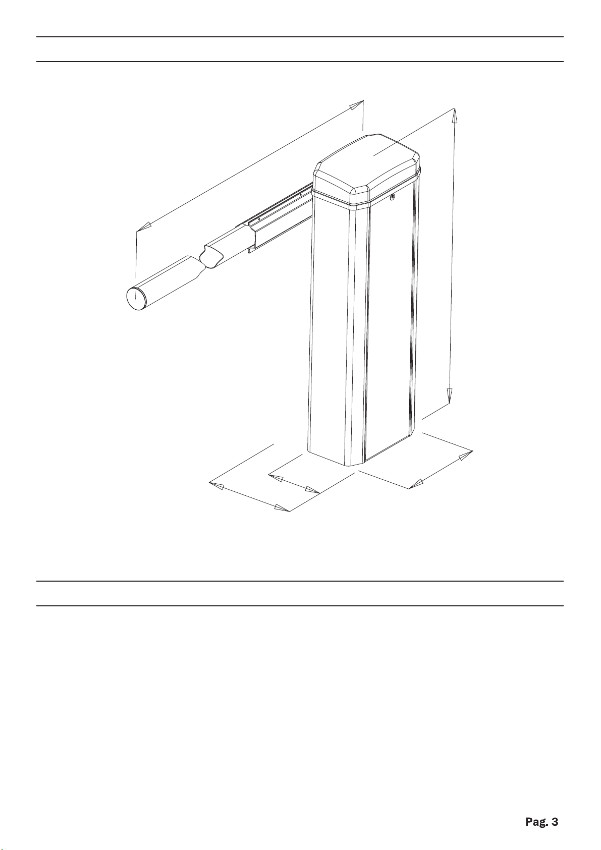
DIMENSIONI
1070mm
2000-6000mm
370mm
230mm
370mm
CONSIDERAZIONI PER L’INSTALLAZIONE
Le operazioni di installazione e collaudo devono essere eseguite solo da
personale qualificato ai fini di garantire la corretta e sicura funzionalità della
barriera automatizzata.
La casa costruttrice, declina ogni responsabilità per i danni derivati da
eventuali errate installazioni dovute ad incapacità e/o negligenza.
6-1624819 rev.2 16/05/2016

MODALITA’ D’INSTALLAZIONE
Predisporre una canalizzazione elettrica al centro della base della barriera, in
corrispondenza del foro centrale - (guaina diam. 25 – 50 mm).
FISSAGGIO CON CONTROPIASTRA
(OPTIONAL)
Prendere la contropiastra e piegare le
zanche in maniera opportuna. Creare uno
scavo a terra di misura adeguata. Inserire
la canalizzazione elettrica all’interno del
foro della contropiastra. Livellare e
cementare la contropiastra.
Posizionare la barriera sulla contropiastra
ed avvitarla tramite i dadi autobloccanti
M12 in dotazione.
Intervenire inserendo la chiave e aprire il coperchio.
inserire la chiave in dotazione nell’apposito grano presente all’estremità dell’albero
motore; avvitare in senso orario fino a battuta, concludendo la manovra di sblocco.
N.B. All’apertura del coperchio l’automatismo va in blocco
FISSAGGIO SENZA CONTROPIASTRA
Posizionare la barriera sulla superfice
desiderata e bloccarla saldamente
tramite I quattro fori di fissaggio
presenti internamente sulla base
APERTURA MANUALE
Fori di fissaggio
1
2
3
4
Contropiastra
Foro guaina
cavi
Dadi
Zanche
Chiave
esagonale
OPZIONALE
6-1624819 rev.2 16/05/2016
Chi
av
e
e
s
a
g
onal
e
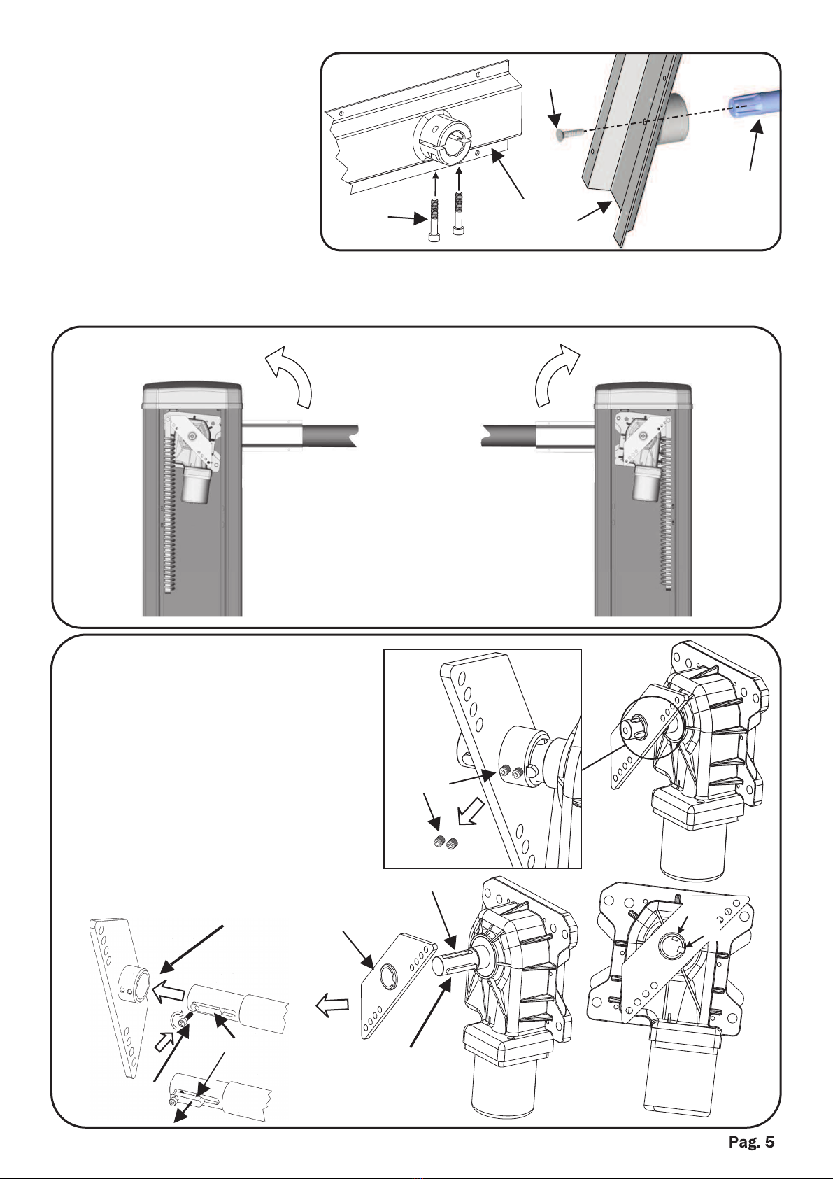
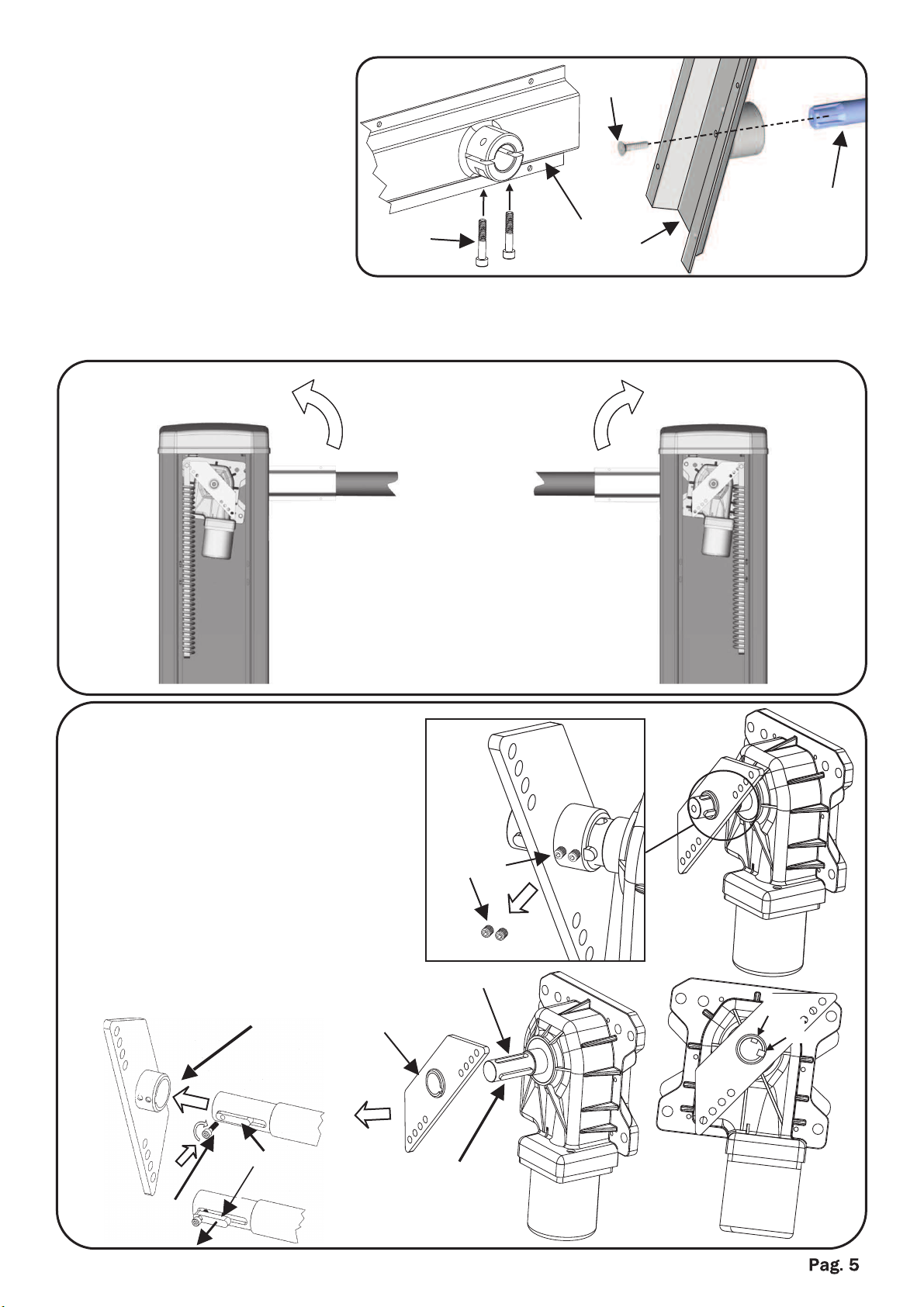
DIREZIONE APERTURA
Per cambiare il senso di apertura dell’automazione da sinistra(standard) a destra
procedere quanto segue:
SXDX
„Sganciare la molla
„Estrarre la staffa trapezoidale
svitando i due grani. Per estrarre
la staffa trapezoidale utilizzare
un estrattore.
„Cambiare la posizione della
chiavetta dalla sede Aalla sede B
dell’albero.
Per estrarre la chiavetta avvitare
la vite (A) 5x20 nel foro fino alla
completa estrazione.
Grani
A
B
SOSTEGNO ASTA
Inserire il sostegno asta
sull’albero e bloccarlo
tramite le viti M8 .
Infilare l’asta nel sostegno e
stringere le relative viti.
Vite
Sostegno
asta
Albero
Viti
6-1624819 rev.2 16/05/2016
SX
DX
Vite A Sede A
Staffa
trapezoidale
Sede B
Chiavetta Chiavetta

„Reinserire la staffa
trapezoidale ed avvitare
i due grani
„Agganciare la molla
nella posizione opposta
(Fori B )
REGOLAZIONE MOLLA Staffa
trapezoidale
REGOLAZIONE FINECORSA
E’ possibile regolare la posizione dei
finecorsa, sia meccanici
(situati internamente alla barriera)
e sia elettrici (raggiungibili facilmente,
posti sotto il coperchio superiore).
N.B. quando si sposta uno dei
finecorsa meccanici, spostare di
conseguenza il relativo finecorsa
elettrico, quindi eseguire una nuova
procedura di programmazione del
quadro elettronico
Micro
finecorsa
elettrico
Vite regolazione
finecorsa
meccanico
Fori regolazione
molla
Lato destro
Fori regolazione
molla
Lato sinistro
Tirante
inferiore
Chiavetta
Sede B
Staffa
trapezoidale
Chiavetta
Sede B
Fori B
Sbloccare il motore.
Mettere in tensione la molla agendo
sul tirante inferiore, fino a quando
l’asta rimane bilanciata a circa 45° e
la staffa trapezoidale rimane in
posizione orizzontale rispetto al
terreno.
Bloccare il motore.
Nella staffa trapezoidale sono presenti
quattro fori, per regolare la forza della
molla, rispetto alla lunghezza dell’asta.
Più si aggancia la molla verso l’interno e
più si riduce la forza.
6-1624819 rev.2 16/05/2016
„
„
„

INCONVENIENTE CAUSA PROBABILE SOLUZIONE
Ad un comando con il
radiocomando o con il
selettore a chiave, la
barriera non si apre o il
motore non parte
Alimentazione di rete
230 volt assente
Controllare l’interrutore
principale
Presenza di STOP di
emergenza
Controllare eventuali
selettori o comandi di
STOP. Se non utilizzati
verificare ponticello su
ingresso contatto STOP
su centralina
Fusibile bruciato Sostituirlo con uno dello
stesso valore.
Cavo di alimentazione del
o dei motori non collegato
o difettoso.
Collegare il cavo
nell’apposito morsetto o
sostituirlo.
C’è un ostacolo in mezzo
alla fotocellula o non
funziona
Verificare il collegamento,
togliere eventuale ostacolo
.
Ad un comando con il
radiocomando non apre,
ma funzione con il
comando a chiave
Il radiocomando non e
stato memorizzato o la
batteria è scarica
Eseguire la procedura di
riconoscimento del
radiocomando sul
ricevitore radio o sostituire
la batteria con una nuova .
La barriera parte, ma si
ferma
La forza del o dei motori è
insufficiente
Modificare il valore con il
trimmer posto
sulla centrale
La barriera inverte
l’apertura con la chiusura
Il collegamento non è
corretto
Scambiare la polarità dei
cavi del motore
interessato
INCONVENIENTI-CAUSE E SOLUZIONI
6-1624819 rev.2 16/05/2016

I dati e le immagini sono puramente indicativi
Il produttore si riserva il diritto di modificare in qualsiasi momento le caratteristiche
dei prodotti descritti a suo insindacabile giudizio, senza alcun preavviso.
AVVERTENZE PER LA SICUREZZA
Le presenti avvertenze sono parti integranti ed essenziali del prodotto e devono essere
consegnate all’utilizzatore. Leggerle attentamente in quanto forniscono importanti
indicazioni riguardanti l’installazione, l’uso e la manutenzione. E’ necessario conservare il
presente modulo e trasmetterlo ad eventuali subentranti nell’uso dell’impianto. L’errata
installazione o l’utilizzo improprio del prodotto può essere fonte di grave pericolo.
ISTRUZIONI PER L’INSTALLAZIONE
L’installazione deve essere eseguita da personale professionalmente competente e
inosservanza della legislazione locale, statale, nazionale ed europee vigente.
Prima di iniziare l’installazione verificare l’integrità del prodotto
La posa in opera, i collegamenti elettrici e le regolazioni devono essere effettuati a
“Regola d’arte”.
I materiali d’imballaggio (cartone, plastica, polistirolo, ecc.) non vanno dispersi nell’ambiente e
non devono essere lasciati alla portata dei bambini in quanto potenziali fonti di pericolo.
Non installare il prodotto in ambienti a pericolo di esplosione o disturbati da campi
elettromagnetici. La presenza di gas o fumi infiammabili costituisce un grave pericolo per la
sicurezza.
Prevedere sulla rete di alimentazione una protezione per extra tensioni, un
interruttore/sezionatore e/o differenziale adeguati al prodotto e in conformità alle normative
vigenti.
Il costruttore declina ogni e qualsiasi responsabilità qualora vengano installati dei dispositivi
e/o componenti incompatibili ai fini dell’integrità del prodotto, della sicurezza e del
funzionamento.
Per la riparazione o sostituzione delle parti dovranno essere utilizzati esclusivamente ricambi
originali.
L’installatore deve fornire tutte le informazioni relative al funzionamento, alla manutenzione e
all’utilizzo delle singole parti componenti e del sistema nella sua globalità.
AVVERTENZE PER L’UTENTE
Leggere attentamente le istruzioni e la documentazione allegata.
Il prodotto dovrà essere destinato all’uso per il quale è stato espressamente concepito. Ogni
altro utilizzo è da considerarsi improprio e quindi pericoloso. Inoltre, le informazioni contenute
nel presente documento e nella documentazione allegata, potranno essere oggetto di modifiche
senza alcun preavviso. Sono infatti fornite a titolo indicativo per l’applicazione del prodotto. La
casa costruttrice declina ogni ed eventuale responsabilità.
Tenere i prodotti, i dispositivi, la documentazione e quant’altro fuori dalla portata dei bambini.
In caso di manutenzione, pulizia, guasto o cattivo funzionamento del prodotto, togliere
l’alimentazione, astenendosi da qualsiasi tentativo d’intervento. Rivolgersi solo al personale
professionalmente competente e preposto allo scopo. Il mancato rispetto di quanto sopra può
causare situazioni di grave pericolo.
6-1624819 rev.2 16/05/2016

BEVLB 24V
TECHNICAL INSTALLATION MANUAL
WARNING!! Before installing, thoroughly read this manual that is an integral
part of the pack
The CE mark conforms to European directive
EEC 89/336 + 92/31 + 93/68 D.L. 04/12/1992 N. 476.
Our products if installed by qualified personnel capable to evaluate risks,
comply with norms UNI EN 12453, EN 12445

PACKING CONTENTS ........................................................................
2
TECHNICAL DATA...............................................................................
2
DIMENSIONS ...................................................................................... 3
CONSIDERATIONS FOR INSTALLATION.......................................... 3
INSTALLATION.................................................................................... 4-5-6
TROUBLESHOOTING.......................................................................... 7
SAFETY PRECAUTIONS ................................................................... 8
1- BARRIER
1- BAR SUPPORT
1- UNLOCKING KEY
Maximum length of bar 3 mt 6 mt
Motors power supply 24Vdc
Motor power 60 W
Motor RPM 1800 / 2400
Condenser /
Mechanical unlock for emergency manoeuvre Mechanical
Working temperature -20° C / +55° C
Weight 45Kg
Protection rating IP 44
Limit switch Electromechanical
Opening time From 5 to 10 seconds *
BEVLB 24V
PACKING CONTENTS
TECHNICAL DATA
* for the fast barrier, it is required
the electric motor with 2400 RPM
6-1624819 rev.2 16/05/2016
DIMENSIONS
1070mm
2000-6000mm
370mm
230mm
370mm
CONSIDERATIONS FOR INSTALLATION
„The installation and testing operations must be performed by qualified personnel
in order to guarantee the proper and safe operation of the automatic gate.
„The company declines any responsibility for damage caused by incorrect
installations due to incompetence and/or negligence.
6-1624819 rev.2 16/05/2016

INSTALLATION
Set up an electrical multi-duct conduit in the middle of the foundation of the barrier,
corresponding to the central hole (corrugated - diameter 25 - 50mm).
INSTALLATION WITH BASE PLATE
(OPTIONAL)
Take the floor plate and bend the brackets
as needed. Dig a suitably sized hole in the
ground. Insert the electrical conduit into the
cable conduit hole of the floor plate. Level
and cement the floor plate.
Place the barrier on the floor plate and
fasten it with the self-locking M12 nuts
supplied.
Open the cover with the key.
insert unlocking key and turn clockwise as in the picture below.
Please note that when the cover is opened the operator goes into block
INSTALLATION WITHOUT BASE PLATE
Place the barrier and block it through the
four holes present internally on the basis.
MANUAL OPENING
Fixing holes
1
2
3
4
Base plate
Cable conduit
hole
Nuts
Brackets
OPTIONAL
6-1624819 rev.2 16/05/2016
SHAFT SUPPORT
Insert the bar support on
the shaft and fasten it with
M8 screws
Insert the bar in the support
and tighten the screws
To change the direction of opening from the left (standard) to the right proceed as
follows:
SXDX
„Release the spring
„Remove the trapezoidal bracket
by unscrewing the two screws.
To remove the trapezoidal bracket,
use an extractor
„Change the position of the key
To remove the key, screw the 5x20
screw (A) in the hole up to the
complete extraction.
from position Ato position B.
Screws
Screw A Position A
Trapezoidal
bracket
A
B
Position B
OPENING DIRECTION
Screw
Bar
support
Screws
Shaft
S
X
DX
6-1624819 rev.2 16/05/2016
Key Key

„Replace the trapezoidal
bracket and tighten the
screws
„Hook the spring in the
opposite position
(holes B)
key
Position B
Trapezoidal
bracket
Holes B
key
Position B
Spring adjustment
holes.
Right side
spring adjustment
holes.
Left side
Bottom
rod
Microswitch
electric limit
switches
Adjustment screw
for the mechanical
limit switches
Trapezoidal
bracket
SPRING REGULATION
„Unblock the motor.
„Stretch the spring acting on lower tie
until the rod will remain balanced at
about 45 ° and the trapezoidal bracket
will remain horizontal to the ground.
The trapezoidal bracket has four holes
which regulate the force of the spring
according to the length of the bar. The
force of the spring is reduced the more it
is placed internally.
LIMIT SWITCHES REGULATIONS
It’s possible to adjust the limit switches
position, both the mechanical
(placed inside the barrier)
and electrical ones (easily accessible,
as they are placed under the superior
cover).
N.B. When one of the mechanical
end-stroke switches is repositioned,
it is necessary to relocate the
electronically controlled one
accordingly, and then repeat the
stroke selecting procedure
6-1624819 rev.2 16/05/2016

PROBLEM PROBABLE CAUSE SOLUTION
On giving a command
with the remote
control or with the
key-switch, the barrier
doesn’t open or the
motor doesn’t start
230 volt mains voltage
absent Check master switch
Emergency STOP
present
Check for any STOP
selectors or commands.
If not used, check jump-
er on STOP contact in-
put on the control board
Fuse blown Replace with one of
same value.
Power cable of motor or
motors not
connected or faulty.
Connect the cable to
appropriate
terminal or replace.
The photocell is not
functioning or the
beam is interrupted
Check the connection,
remove any
obstacle across the
beam
On giving a command
with the remote control,
the barrier doesn’t open
but
works with the key
command
The remote control has
not been
memorised or the bat-
tery is flat
Carry out the remote
control learning
procedure on the radio
receiver or replace the
battery with a new one.
The barrier starts, but
stops immediately
The force of the motor or
motors is insufficient
Modify the value with the
trimmer on the
control unit
TROUBLESHOOTING
6-1624819 rev.2 16/05/2016

The data and images are for guidance only
reserves the right to change at any time characteristics of the products described in its
sole discretion, without notice.
SAFETY PRECAUTIONS
These warnings are an essential, integral part of the product and must be given to the user. They
provide important indications on the installation, use and maintenance and must be read carefully.
This form must be preserved and passed on to subsequent users of the system.
The incorrect installation or improper use of the product may be dangerous.
INSTALLATION INSTRUCTIONS
" The installation must be performed by professionally skilled personnel and in compliance with
current local, state, national and European legislation.
" Before beginning the installation, check the integrity of the product.
" The laying of cables, electrical connections and adjustments must be workmanlike performed.
" The packing materials (cardboard, plastic, polystyrene, etc.) are a potential hazard and should
be disposed of correctly and not left within reach of children.
" Do not install the product in potentially explosive environments or environments disturbed by
electromagnetic fields. The presence of inflammable gases or fumes is a grave danger to
safety.
" Set up a safety device for overvoltage, a disconnecting and/or differential switch suitable for
the product and conforming to current standards.
" The manufacturer declines any and all responsibility for product integrity, safety and operation
in the event incompatible devices and/or components are installed.
" Solely original spare parts should be used for repairs and replacements.
" The installer must provide all the information relating to the operation, maintenance and use of
the individual parts, components and system as a whole.
WARNINGS FOR THE USER
" Read the instructions and enclosed documentation carefully.
" The product must be used for the express purpose for which it was designed. Any other use is
considered improper and therefore hazardous. In addition, the information given in this
document and in the enclosed documentation may be subject to modifications without prior
notice. It is given as an indication only for product application. The company declines any
responsibility for the above.
" Keep products, devices, documentation and anything else provided out of reach of children.
In the event of maintenance, cleaning, breakdown or faulty operation of the product, cut off the
power and do not attempt to operate on the product. Contact solely the professionally skilled
personnel responsible for these operations. Failure to adhere to the above indications may be
dangerous.
6-1624819 rev.2 16/05/2016

BEVLB 24V
MANUEL D’INSTALLATION
ATTENTION! Avant d’effectuer l’installation, lire attentivement le présent
manuel qui fait partie intégrante de cet emballage.
Le marquage CE est conforme à la directive européenne
CEE 89/336 + 92/31 + 93/68 D.L. 04/12/1992 N. 476.
Nos produits, si installés par du personnel qualifié capable d'évaluer les
risques, sont conformes aux normes UNI EN 12453 - EN 12445.
Composition de l’emballage ................................................................
2
Données techniques ...........................................................................
2
Dimensions ......................................................................................... 3
Considérations pour l’installation ........................................................ 3
Modalité d’installation .......................................................................... 4-5-6
Inconvénients: causes et solutions ......................................................
7
Conseils et sécurité ............................................................................. 8
CONTENU DE L’EMBALLAGE
1- BARRIERE
1- SUPPORT BARRE
1- CLE DE DEBLOCAGE
DONNES TECHNIQUES
Longueur maximum barre 3 mt 6 mt
Alimentation moteur 24Vdc
Puissance moteur 60 W
Révolutions moteur
Condensateur /
Déverrouillage mécanique pour manoeuvre d’émergence Mécanique
Température de fonctionnement -20° C / +55° C
Poids 45Kg
Degré de protection IP 44
Fin de course Electromécanique
Temps d’ouverture
* Pour la barrière rapide, il est nécessaire
le moteur électrique à 2400 tpm.
6-1624819 rev.2 16/05/2016
1800 / 2400
BEVLB 24V
De 5 à 10 secondes *

DIMENSIONS
1070mm
2000-6000mm
370mm
230mm
370mm
CONSIDERATION POUR L’INSTALLATION
Les opéra ons d’installa on et essai doivent être exécutées seulement par du
personnel qualifié pour garan r la correcte et sûre fonc onnalité de la barrière
automa sée.
Le constructeur, décline toute responsabilité pour les dommages causés par
des installa ons incorrectes dues à incapacité ou négligence.
6-1624819 rev.2 16/05/2016

MODALITE D’INSTALLATION
Mettre au point une canalisa on électrique au centre de la base de la barrière, en
correspondance du trou central – (gaine diam.25-50 mm).
FIXAGE AVEC LA CONTRE PLAQUE
(OPTIONNEL)
Prendre la contre plaque et plier les pa es
d’ancrage de façon appropriée. Créer une
excava on à terre de mesure adéquate.
Insérer la canalisa on électrique à
l’intérieur du trou de la contre plaque.
Niveler et cimenter la contre plaque.
Posi onner la barrière sur la contre plaque
et la visser par les écrous autobloquants
M12 en dota on.
Intervenir en insérant la clé et ouvrir le couvercle.
Insérer la clef en dota on dans le spécial grain présent à l’extrémité de l’arbre de transmission;
visser en direc on horaire jusqu’à la butée, en concluant la manoeuvre de déblocage.
NOTE. A l’ouverture du couvercle l’automa sme se bloque.
FIXAGE SANS LA CONTRE PLAQUE
Posi onner la barrière sur la surface
désirée et la bloquer solidement par
les quatre trous de fixage présents
intérieurement sur la base.
OUVERTURE MANUELLE
Trous de fixage
1
2
3
4
Contre plaque
Trou gaine
câbles
Écrous
Pattes
OPTIONNEL
6-1624819 rev.2 16/05/2016
d’ancrage
Clef à
six pans
Table of contents
Languages:
Other Allmatic Control System manuals


