Smart Candle LV96 User manual

The Low Voltage lighting system can power up to 96 candle pods split over 4 different independent channels.
24 candles can be powered per output channel.
Low Voltage is a revolutionary lighting system which has been purposely designed to minimise interaction
with electronic candles. The candles can be powered at the touch of a button using mains power. No need
to change any batteries or turning on by hand or remote control.
Items Required for LV96 System:
LV96 Control Box
Power Adaptor with A/C Lead
Low Voltage Candles
Low Voltage Cable
Plug and Go connection cables (Optional)
Installation Items Required:
Number 1 Size Philips style screw driver
Wire Stripper
Wire Cutter
Power Lead:
The power adaptor that is supplied with the control box is a switch mode unit, it will operate from 100V –
240 volts.
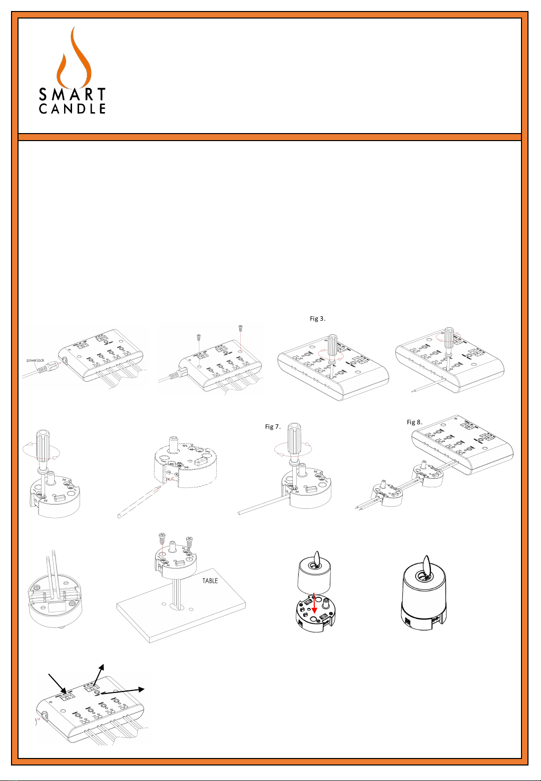
First connect the small socket from the power adaptor into the input socket on the control box (SEE FIG 1).
Then insert the mains plug into a A/C mains outlet socket.
The control box can be mounted onto a wall or shelf with the designated screw holes that are located on
either end of the control box. (SEE FIG 2)
LV96 Instructions
Installation:
The Low Voltage systems are designed to check that each pod is being wired in to the system correctly i.e. polarity, as
you install. The pods which are being installed will have an LED Indicator on them. For this feature to work, it is
important that the control box is connected to the mains via the power lead, and the switch is
in the on position. The control box LED will illuminate “RED”showing that power is running to the control box
(SEE FIG 1). When pods are installed into the system the LED indicators will illuminate if they are correctly
wired and installed.

Wiring the Pods:
**Make sure the Control box power is switched ON**
Polarity:
The “Copper”coloured wire should always be connected to the “+”connectors at the control box terminals
and candles pods.
The “Silver”cable should be connected to the “-”connectors at the control box terminals and candle pods.
Connecting the candles:
Each control box has 4 output channels. Each output channel can run a maximum of 24 candles.
Using a screwdriver loosen the output channel wire securing screws. Strip the plastic from the low voltage
cable by approximately 1cm and insert the cables observing the correct polarity as explained above. Copper
colour into “+”and Silver into “-”. Once both cables are in their respective terminals, secure the screws
with a screw driver.
This process is repeated per output channel. (SEE FIG 3, FIG 4)
Connecting pods into the system:
Unscrew cable connection securing screws on the pods. Strip the plastic from the wire by approximately 1cm
and as above insert the correct colour wire into their respective terminals. COPPER INTO “+”and SILVER
INTO “-”. Once this step is completed, secure the screws back into place.
Plug and Go connectors are available. These simply plug from port to port located on each candle pod.
If the LED indicator is GREEN on the candle pod this has been done correctly.
Repeat this process from Pod to Pod. (SEE FIG 5, FIG 6, FIG 7, FIG 8)
Concealing Cable:
For situations where the cable needs to be concealed the output cables can be clipped to the under side of
the pods using the clips on the underside of the pod. (SEE FIG 9)
The pods can be secured to a surface using the screw holes integrated into the pod. (SEE FIG 10)
Fitting the candles:
Low Voltage candles are extremely easy to install. Simply place the Low Voltage candles onto their
corresponding pods, making sure the socket on the bottom of the candle is fully placed onto the power
socket on the pods. (SEE FIG 11, FIG 12)
LV96 Instructions

Control Box Features:
On/Off Mode
Reset Button (Individual Channel on and off)
Timer Mode
On/Off Mode: When in the “ON”position the whole system (every channel) will remain on until the switch is
turned to the “OFF”position.
Reset Button: Press and hold the reset button on any channel to turn this individual channel on or off. A
“RED LED”will illuminate and the candles in this channel will turn off. Press once again and the “RED LED”
will go out and the candles for this channel will turn back on. Repeat as needed on any channel.
If switched to "Timer" mode then you can select the amount of time you want the system on for
TIMER PERIOD 8 / 12 / 16 Hours
TIMER RESET
The timer is based on a 24 hour period , so if you select 12 hours then the system will be "On" for 12
Hours and "Off" for 12 hours.
Select the time you want , 8 , 12 , or 16
When you have set the switch to the desired time Press the "TIMER RESET" Button located next to the timer
mode switch. Pushing the button will start the timer system if you want to reset the time then press the
timer reset button again;
E.G: 12 Hour Timer
Time on 12.00 Noon: Press the reset button at 12 Noon and At Midnight the system will turn Off
Note switching between timer settings will reset the timer
If the control box power is switched off at the A/C supply this will also reset the timer. If the power to the
control box has been interupted then the timer will need to be reset
Other Information:
When the system is switched "ON" , or switched from "Normal Mode to "Timer Mode" or switched between
"Timer" settings i.e. 8 hours to 12 hours the "RED" LED Indicator lights will come on and go off in sequence
from right to left. This is normal and the system is self re-setting.
RESET LED Indicator:
If there is a problem in a certain channel the Reset LED will illuminate for that channel, this could be caused by:
Polarity being incorrect
Too many candles in the line (24 Maximum per output channel)
NOTE: This will only occur when candles are fitted onto their respective pods.
(SEE FIG 13 –WHOLE PAGE)
LV96 Instructions
RESET LED Indicator on Power Lead:
This Low Voltage system has overload/surge protection. Should anything power related occur a “RED LED”will
illuminate on the little box on the power lead. By pressing the “reset”button next to the LED this will reset
the system. Once this is pressed the system will function as normal.
Note: By adding too many candles into the system could cause this to illuminate.
A MAXIMUM OF 96 CANDLES CAN BE USED PER SYSTEM
A MAXIMUM OF 24 CANDLES PER OUTPUT CHANNEL CAN BE USED
A MAXIMUM of 25 Metres to the first candle can be achieved. Thereafter between candles 2 metres can be
achieved. (Candles could go dim if more than this is attempted)
Fig$2 . Fig$3 . Fig$4.
Fig$5 . Fig$6. Fi g$7. Fig$8 .
Fig$9 . Fig$11 . Fig$12.
Normal/OFF/Timer Ti m er$ 8 /1 2 / 1 6 $ Hou rs
Ti m er$ Res et
Fig$1 3.
Fig$1 0.
Fig$1 .
LV96 Instructions
Table of contents
Popular Home Lighting Accessories manuals by other brands

Monzana
Monzana Julelys MZPL42 manual

MOB
MOB MO6611 user manual

Home Accents Holiday
Home Accents Holiday TY415-1911 Assembly instructions

Fraser Hill Farm
Fraser Hill Farm FCRY060-SNM1-WT manual

MELINERA
MELINERA HG01038A Operation and safety notes

Home Accents Holiday
Home Accents Holiday OMS THD Assembly instructions


Home Accents Holiday
Home Accents Holiday TY048-1411 Use and care guide

Steren
Steren Shock Ball user manual

GE
GE Pro-Line ConstantON 80756LO Assembly instructions

Morris
Morris MR-124911 Easy Assembly and operation instructions

Home Accents Holiday
Home Accents Holiday TY152-1314 Use and care guide

FLOS
FLOS RF29125 quick start guide