smart home 7307 User manual


–2–
Your Guide to the
Total Protection Alarm System
SMARTHOME™ #7307
–3–
PACKAGE CONTENTS........................................................................4
OVERVIEW........................................................................................5
PLANNING YOUR HOME SECURITY NEEDS.......................................6
INSTALLATION
-Control Panel...................................................................................7
-Door/Window Sensor........................................................................8
-Motion Sensor..................................................................................9
TESTING YOUR SYSTEM.................................................................11
LIGHTS AND SOUNDS......................................................................12
STANDARDPROGRAMMING
-Arming and disarming the Security System using the Keypad.............13
-Arming and disarming the Security System using the Keychain
Transmitter.....................................................................................15
-Panic Button on the Keychain Transmitter.........................................16
PASSWORDS
-Master Personal Identification Number (MPIN)...................................17
-Secondary Personal Identification Number (SPIN)..............................18
ADVANCEDPROGRAMMING
-Program Sensors to Different Zones.................................................19
-To clear a zone...........................................................................20
-To program a sensor to a zone.....................................................20
-To delete a Keychain Transmitter from zone 5................................21
-ToprogramaKeychainTransmitter or keypad transmitter (option)
to zone 5....................................................................................21
-Standard Arming Sequences...........................................................22
-Additional Arming Sequences..........................................................22
-Customize a Sequence...................................................................24
SUMMARY OF ARMING SEQUENCES..............................................25
BATTERYMAINTENANCE
-Control Panel.................................................................................26
-Motion Sensor................................................................................27
-Door/Window Sensor.......................................................................27
-Keychain Transmitter.....................................................................28
ADDITIONAL ACCESSORIES (OPTION).............................................29
TABLE OF CONTENTS
SMARTHOME.COM™ 1-800-SMART-HOME 949-221-9200 http://www.smarthome.com Order #7307

PACKAGE CONTENTS
Everythingrequiredforinstallationisincludedwith this package
1 ControlPanel(SC-001)includes:
1 antenna(installed)
1 AC adapter
1 9 volt alkaline battery
Twosets of Door/Window Sensors
(WT-433),eachsetincludes:
1 transmitter
1 magnetic switch
1 magnet
2 spacers
112voltalkaline battery (installed)
1 Motion Sensor (PS-433) includes:
1 9 volt alkaline battery (installed)
1 KeychainTransmitter(4B-434)includes:
1 12 volt alkaline battery (installed)
3 Packs of screws and anchors
(forControl Panel, Door/Window Sensors and Motion Sensor)
Sheetoftemplates
DoubleSided Tape(to aid in the installationof the Control Panel, Door/
WindowSensorsandMotionSensor)
Warning Stickers 2 pcs
Manual
WarrantyCard
QuickGuide –5–
OVERVIEW
Congratulations!
You have just purchased one of the most reliableand up-to-date wireless
security systems on the market today. Skylink is the first company to in-
corporate the rolling code technology in a home/business security system.
This innovative technology provides increased security and troublefree
wirelessconnectionswhich greatly reduces false alarms. It guarantees that
the Control Panel will only recognize radio waves from it’s remote sensors,
(door/windowsensor, motionsensor and the keychain transmitter), which
preventshigh tech thieves from duplicating signals and tampering with your
system.
Thismanualisdivided into 6 categories.
1. Planning, Installation and Testing (pages 6-11)
- explains how to plan a security strategy.
-howtoinstalltheControlPanel and the remote devices, (door/window
sensor and the motion sensor).
- once everything is installed, explains how to test each device.
2. Lights and Sounds (page 12)
- explains the function of all the lights on the Control Panel.
- describes all the sounds emitted from the Control Panel.
3. Standard Programming and Passwords (pages 13-18)
- how to arm and disarm the system using the Control Panel.
- how to use the 4 button keychain transmitter to arm and disarm the Control
Panel.
-how to personalize your MPIN (Master Personal Identification Number).
-how to program a SPIN (Secondary Personal Identification Number).
4. Advanced Programming (pages 19-24)
- the ControlPanelreceives signalsfromtheremote sensorsinfourdifferent
zones.Explains how to program different remote sensorstodifferentzones.
-the Control Panel is programmed with different alarm modesfordifferent
situations. Explains how to program these alarm modes.
-explains the different alarm sequences preprogrammed at the factory for
yourconvenience.
5. Summary Table (page 25)
-summarizes all preprogrammed alarm sequences.
6. Maintenance (page 26-28)
- explains how to change batteries in all remote sensors and the Control
Panel.
–4–
SMARTHOME.COM™ 1-800-SMART-HOME 949-221-9200 http://www.smarthome.com Order #7307

–6–
PLANNING YOUR HOME SECURITY NEEDS
Before you begin to install your security system, analyze the premises to
determineyoursecurityneeds.Considerthosedoors and windows which
are more likely to be used as points of entry by an intruder, the ones that
are poorly lit or the entrances that can not be seen from the street.
Sketchamap of the premises and determine which doorsand/orwindows
needcontact sensors and whichareasofthe premisesneedtobemonitored
byamotionsensor. Werecommend that you put one door/window sensor
onthe door you enter/exit from most often,theothersensoronyoursecondary
entranceandyourmotionsensormonitoringthe bedrooms, (stairway or
hallwayleading to the bedrooms).
Ifyouhavedeterminedthatyouneed additional sensors, see Additional
Accessories on page 29.
Below is an example of how to position your security system in a house.
You may choose to install a motion sensor to protect any valuables such as
antiques or paintings. Point the motion sensor directly at the valuables and
if they are disturbed in any way the alarm will be sounded.
BEDROOM
BEDROOM
MASTER
BEDROOM
DOOR/WINDOW
SENSOR
DOOR/WINDOW
SENSOR
BACKDOOR
FRONT
DOOR
CONTROLPANEL
MOTIONSENSOR
BATHROOM
LIVINGROOM
DININGROOM
KITCHEN
–7–
INSTALLATION
TheControlPanel,door/window sensors and the motion sensor are installed
using the screws included. Wehave alsoincludeddouble sided tape, (forthe
door/windowsensorandthemotionsensor)tousefortemporaryinstallation
while you are positioning the sensors. Once all the sensors are positioned
correctly, install them permanently with the screws. We have also included
wall anchors and templates to help position the screws correctly.
How to use the templates:
1.Cutthetemplaterequired
2. Tape it in position
3. Screw part way into the surface where the holes are marked
4.Unscrewthescrews and remove the template
5. Screw the component in place where you started the screws
INSTALLING THE CONTROL PANEL (SC-001)
Position the Control Panel near the door you use to enter/exit from most
often and within access of an electrical outlet. The Control Panel runs on
regular electrical current. It also contains a 9 volt backup alkaline battery in
case power is interrupted for any reason.
There are 3 ways to attach the Control Panel on the wall:
1. Use double sided tape for temporary use.
2. Hanging it from the two keyholes on the two stationary screws.
3. Screwing the back onto the wall with 4 screws.
To mount the Control Panel:
1. Open the case.
a) Press the two tabs on top of the
Control Panel
b) Pull open the front
2. Threadthe AC adapter cord through
the large hole in the back of the unit
and plug it into the circuit board as
shown. The Adapter cord must be
inserted through the back of the
unit before it is attached to the
wall.
3. Insert the 9 volt alkaline battery and
rotatethe antenna from the inside of
the Control Panel to the outside.
SMARTHOME.COM™ 1-800-SMART-HOME 949-221-9200 http://www.smarthome.com Order #7307

4. Attach the unit to the wall. If hanging the
unit, insert two screws using the template
provided.Ifscrewingthe back directly to
the wall, take the back plate right off by
prying apart one hinge. Use as much
forceas needed. The plastichingewillnot
break.
5. Using the template, attach the backplate
on to the wall with 4 screws.
6. Mount the Control Panel on the backplate.
Insert one hinge into the hole, then twist
the other hinge into position.
7. Firmly close the case.
8. Plug the AC adapter into a power outlet.
The red AC PWR light and keypad back-
light will be on.
INSTALLING THE DOOR/WINDOW SENSOR (WT-433)
It is recommended to install one sensor on your front door and the other on
yourbackdoor.
Each contact sensor has 4 parts:
INSTALLATION
Transmitter Magnetic Switch Magnet Spacers
1. Position the transmitter be-
sidethedoor/windowframeon
thewallusingeither two sided
tapeor screws. If you are using
screws,firstpry off the back plate
withasmall screwdriver and
screw the back plate into posi-
tionusing the template. Then click
the transmitter on to the back
plate now mounted on the wall. –9–
INSTALLATION
2. Position the magnetic switch connected to
thetransmitter on the door/window frame.
3. Position the magnet on the door beside the
magnetic switch. They should be no more
than 1 cm (3/8 inch) apart. When the door/
window is closed, the magnets are in contact.
Whenthedoor/windowisopened,contactis
broken and the transmitter sends a signal to
the Control Panel to activate the chime or
alarm.
INSTALLING THE MOTION SENSOR (PS-433)
The motion sensor senses motion from up to
13 meters, (40 feet) away in a 110 degree arc.
It works best when installed from 2 meters,
(approx.7feet)offthe ground in a corner.
Please position the sensor so that it is looking
downatanangleofabout12 degrees.
We recommend that you position the motion
sensorwhereitwill guard the bedrooms. For
example,have your motion sensor monitoring
the stairway which leads to all the bedrooms
upstairs. A hallway or central area can also be
used.
1. Once you have decided on a location, tape
the template into position. If you are putting
the motion sensor in a corner, first fold the
template along the center line so it will fit
snugly into the angle. Screw the two mount-
ing screws in position, (if installing on a flat
wall,usethescrewholesoneabovetheother,
if installing in a corner, use the screw holes
on sides of the unit).
2. Insert the 9 volt alkaline battery.
(original battery inserted by factory)
3. Match up the two screws with the appropriate
two keyholesonthe back of the Motion Sensor,
then hang the unit in position.
–8–
SMARTHOME.COM™ 1-800-SMART-HOME 949-221-9200 http://www.smarthome.com Order #7307

–10–
(Cont.:Installingthemotionsensor(PS-433)
Set the switch on the side to"TEST" andallow 60seconds for the unit to warm
up. ( when using test mode, a signal will not be sent to the Control Panel ).
Now walk in the area you want the motion sensor to detect movement in.
If movement is detected, the red light on the front of the unit will appear. If
theredlight does not appear, movement hasnotbeen detected and you
shouldrepositionyourmotionsensor.
PULSE COUNT FEATURE
Your Motion Sensor is equipped with Pulse
Countfeature.Thisnew featuresignificantly
reducesfalsealarms.NowwhenPulse
Countis enabled2consecutivemovements
arerequiredinordertotriggerthemotion
sensor. However, the response time of the
motionsensorwillbecomeslower.Therefore
youhavethe option to either enable or dis-
able this feature to suit your specific needs.
The factory default for this feature is set to
“ON”.Yourcandisablethisfeatureby relocat-
ing the Pulse Count jumper, which is the red
jumperlocatedinsidethe battery compart-
ment. When the red jumper is on the left 2
posts(Diagram1), Pulse Count feature is
enabled. If you would like to disable Pulse
Count,please remove the redjumperand
insert it on the right 2 posts (Diagram 2).
Note: When installing the Motion Sensor,
avoidplacingitnearheatorcoldproducing
devices(i.e.A/Corfurnace vents, fans,ovens,
spaceheatersetc.).Airmovement,especially
causedby changes in temperature may
triggerthe Motion Sensorand cause false
alarms. Please carefully test your Motion
Sensor to make it will only be triggered by
people.
Installation is now completed and now test your system to ensure all the
sensors are communicating with the Control Panel. (See the next section,
TESTINGYOURSYSTEM)
INSTALLATION
ENABLE PULSE
COUNT(DEFAULT)
DIAGRAM 1
DIAGRAM 2
DISABLE PULSE
COUNT
Insert jumper to
the right 2 posts
Before you learn how to use your security system, test to make sure that
thedoor/windowsensors andthe motionsensor arecommunicating withthe
ControlPanel.
Set the Control Panel to CHIME MODE which will emit a subtly two tone
chimewhen any of the sensors areactivated.
To set control panel to CHIME MODE
1.Enter your MPIN[0, 0, 0] on the Control Panel (MPIN isfactory set at [0, 0, 0].
TochangeMPINseeMASTER PERSONAL IDENTIFICATION NUMBER
(MPIN) on page 17.
2. Press [ A ].
3. Press [ # ].
Theredarm light and all 4 green lights abovethenumbers and beside the
word chime will go on. The system will now emit a chime sound when any
sensorisactivated.ThelightsandsoundsoftheControlPanelareexplained
in the next section, (see Lights and Sounds).
Thedoor/windowsensors are factoryset to communicate with zone 1and
the motion sensor to communicate with zone 2. If you would like to have the
sensorscommunicatewithadifferentzone,seePROGRAMSENSORSTO
DIFFERENTZONES onpage19.
To test the Door/Window Sensor
Openthedoor/windowand break the contact between the magnetic switch
and the magnet. A signal will then be sent to the Control Panel which will
chime telling you that the signal has been received. One of the four green
lights on the Control Panel will flash once as the chime sounds. If you open
thefrontdoor, the greenlightabovethe #1 (zone 1) will flash.
To test the Motion Sensor
Slide the button on the side of the motion sensor to ON and allow 60 seconds
for the unit to warm up,then walk inthe monitored area in frontof the motion
sensor. Once movement is detected, a signal will be sent to the Control Panel.
TheControl Panel will then emit a two tone chime and the green light above
the#2 (zone 2) will flash once. Themotion sensor has been programmed to
send its signal to zone 2 in the Control Panel. It will take about 30 seconds
for the motion sensor to reset itself before it can send another signal.
If you havepets, havethem walk in the monitored area to see if they activate
the motion sensor. If so, turn the motion sensor off if thesepets have access
tothe monitored area. Smaller pets will not be picked up by the motion
sensor. –11–
TESTING YOUR SYSTEM
SMARTHOME.COM™ 1-800-SMART-HOME 949-221-9200 http://www.smarthome.com Order #7307

LIGHTS AND SOUNDS
If you make a mistake while programming, the Control Panel emits three
short beeps. That means the system has cleared and you must start the pro-
grammingsequence from the beginning. If you get lost in the programming
sequence or have made a mistake and want to start over again, press the [ * ]
on the key pad of the Control Panel until you hear three short beeps. This will
clear the system, then you can start again from the beginning. If no button is
pressed for eight seconds while in the middle of a programming sequence,
the system will also clear itself.
Below is an explanation of the lights and sounds of the Control Panel.
LIGHTS
ACPWR light on System is being powered by electrical current.
ACPWR lightoff System is not receiving any electrical power.
LOBATT. lightoff Backup battery is connected and working.
LOBATT.light flashing Backup battery is weak, needs to be replaced.
ARMlightoff System is disarmed.
ARM light on System is armed.
Key Pad Back Light Ifpowered by AC adapter - back light is always on
If powered by back up battery only - stays on for
eight seconds when any button is pressed.
Greenlights above#1-4 System will emit a two tone chime when a sensor
isactivated,CHIMEMODE.
Red lightsbelow #1-4 System will sound alarm instantly when a sensor
isactivated, INSTANTMODE.
Bothgreenandredlights System will beep steadily for 30 seconds when
#1-4 a sensor is activated, after the 30 seconds the
alarmwillsound,DELAYENTRYMODE.
Bothgreenandredlights Lightswillflashfor45seconds. Allremotesensorspro-
flashing grammedto that zone will not communicate with the
ControlPanelforthose45seconds,whichgivesyou
time to exit the premises before the system is armed.
SOUNDS
Threeshort beeps You have made a mistake, start again.
Longbeep You have successfully completed a command.
Short beep You have pressed a key in the right order.
Twotone chime A device has been activated in CHIME MODE.
Siren(3 minutes) A device has been activated in INSTANTMODE.
Steadyrepeated beep The alarm has been triggered in DELAY MODE.
You have 30 seconds to disarm the system
beforethe alarm sounds.
Twotone beep System is set on exit delay, you have 45 seconds
to leave the premises once the system has been
activated. After the 45 seconds, the system emits
a two tone beep and the system is now armed.
Now that the system is installed and the sensors are communicating with the
Control Panel, it is time to learn how to do basic programming of your security
system.Moreadvancedfeaturesareexplainedfurtherinthemanual,(see
AdvancedProgramming).
You can arm and disarm the systembyusing either the keypad on the Control
Panel or the 4 button keychain transmitter or keypad transmitter (option).
TO ARM THE SYSTEM USING THE KEYPAD ON THE CONTROL
PANEL
All programming sequences begin with theMaster Personal Identification
Number (MPIN). There is only one MPIN which has been factory set at 0 0 0.
You can also assign up to 3 different Secondary Personal Identification
Numbers (SPIN). Formoreinformation on how to change your MPIN and
how to add an SPIN, (see PASSWORDS on page 17, 18).
Wehave preprogrammed 6 different arm sequencestomeetdifferent cir-
cumstances. For example, if you would like the system activated while you
are in the premises, the motion sensor will be turned off so you have the
freedom to move about without setting off the alarm. You can personalize
anyofthesepreprogrammedarmsequences,(seeAdvancedProgramming).
Arming sequences
Option 1: Away Sequence - To arm your system when you are the last
person leaving the premises.
1. Press the current MPIN [ 0 0 0 ].
2. Press [ B ].
3. Press [ C ].
You hear a long beep. The arm light and the red lights in zones 3 and 4 go
on.Both the green and red lights flashin zone 1 for 45 secondswhich gives
you 45 seconds to leave the premises before the system is activated. After
45 seconds, both the green and red lights in zone 1 and 2 remain on. Upon
re-enteringthepremisesthroughzone1,or walking in the monitored area
of the motion sensor, zone 2, you have 30 seconds till the alarm sounds.
The system gives you 30 seconds from the time you enter the premises, for
example opening the front door, to get to the Control Panel to deactivate the
system. Zones 3or 4remain instant. Ifany sensor in zone 3and4 are activated,
the alarm sounds instantly. –13–
STANDARD PROGRAMMING
–12–
SMARTHOME.COM™ 1-800-SMART-HOME 949-221-9200 http://www.smarthome.com Order #7307

–14–
STANDARD PROGRAMMING
Option 2: Home Sequence - To arm your system when someone
remains in the premises.
1. Press the current MPIN [ 0 0 0 ].
2. Press [ C ].
Youheara long beep.Thearm lightandthe redlightsin zones3and 4 goon.Both
thegreenandredlightsflashinzone1for45seconds whichgivesyou45seconds
to leave the premisesbefore thesystem is activated. After 45 seconds, both the
greenandredlightsinzone1remainon.Uponre-entering thepremises through
zone 1, you have 30 seconds till the alarm sounds. The system gives you 30
secondsfromthe time youactivatethedoor/windowsensor,forexampleopening
thefrontdoor,togettotheControl Panelto deactivatethesystem.Zone2remains
offwhichallows thepersoninthepremisestomovearoundwithoutactivatingthe
motion sensor. Zones 3 and 4 remain instant. If any sensor in zone 3 or 4 are
activated,thealarmsounds instantly.
Option 3: Night Sequence - To arm your system when there are people
in the premises and no one is expected to enter or exit. Example at
nightwhen everyone is sleeping.
1. Press the current MPIN [ 0 0 0 ].
2. Press [ A ].
3. Press [ B ].
You hear alongbeep.Thearmlight, the red light inzones1,3& 4 go on. If any of
thesensorsareactivatedinanyofthese3zones,thealarmissoundedinstantly.
Zone2,themotionsensor,remainsoffallowingmovementthroughoutthepremises.
TO DISARM THE SYSTEM USING THE KEYPAD ON THE CON-
TROL PANEL
1. Press the current MPIN [ 0 0 0 ].
2. Press [ # ].
All the lights but the AC PWR light go off. The system is now disarmed.
Note: If [MPIN,#] is entered when the system in not activated, the system
will default back to the last sequence before the unit was turned off.
Emergency Silent Alarm works in conjunction with the Emergency Dialer
(option), see Additional Accessories.
Ifunderduress when disarming the system:
1. Enter the current MPIN [ 0 0 0 ].
2. Press [ B ] [ B ].
Thiswillterminatethedelaymode(stopthesteadyrepeatedbeep)andreturn
to the previous arm mode. It will also send a signalto the Emergency Dialer
silentlywhich will then automatically send a prerecorded message forhelp.
The Keychain Transmitter conveniently fits on any keychain. It allows you to
arm and disarm the system from a distance of approximately 100 feet from
the Control Panel. The distance will depend on what is between the key-
chain transmitter and the Control Panel. It also has a panic button that lets
you remotely activate the siren instantly.
Note: Make sure you press down on the transmitter for one full second or
the system may not respond.
–15–
TO ARM SYSTEM USING THE KEYCHAIN TRANSMITTER
Thereare 2 different arm options to choose from:
1. Press button #1, and the Control Panel will beep once.
The system will be armed in the Away Sequence. To be used to arm the
system when you are the last person leaving the premises. (see
page13for information on the Away Sequence).
Pressing button #1 will give you the same result as pressing:
MPIN, [ B ] , [ C ] on the keypad.
2. Press button #2, and the Control Panel will beep once.
The system will be armed in Home Sequence. To be used to arm the
system when someone remains in the premises. (see page 14 for
informationon the Home Sequence).
Pressing button #2 will give you the same result as pressing: MPIN, [ C ]
on the keypad.
PANIC
2
1
3
KEYCHAIN TRANSMITTER (4B-434)
SMARTHOME.COM™ 1-800-SMART-HOME 949-221-9200 http://www.smarthome.com Order #7307

–16–
KEYCHAIN TRANSMITTER (4B-434)
TO DISARM THE SYSTEM, OR DEACTIVATE THE SIREN USING
THE KEYCHAIN TRANSMITTER
When the system is armed:
Press button #3.
The red light on the transmitter flashes and the Control Panel beeps twice.
The system is now disarmed.
When the siren is sounding:
Press button #3.
The red light on the transmitter flashes and the siren is deactivated.
THE PANIC BUTTON ON THE KEYCHAIN TRANSMITTER
Both the ControlPanel andthe keychaintransmitter are equipped with panic
buttons. It doesn’t matter what mode you are in or even if the system is off,
once either panic button is pressed, the siren comes on instantly. The alarm
will continue to sound for 180 seconds or until the system is disarmed.
The panic button on the keychain transmitter is the larger red button.
The panic button on the Control Panel is the red button on the keypad.
–17–
PASSWORDS
MASTER PERSONAL IDENTIFICATION NUMBER (MPIN)
Security access to the SC-100 is controlled by a MASTER PERSONAL
IDENTIFICATION NUMBER (MPIN) or SECONDARY PERSONAL
IDENTIFICATIONNUMBER(SPIN).All programming sequencesstartwith
eitherthe MPIN or SPIN.
To Change your MPIN:
1. Enter the current MPIN, (the MPIN is factory preprogrammed with
0 0 0).
2. Press [ * ].
3. Press [ 0 ].
4. Press [ * ].
5. Enter your new MPIN, (your MPIN must be a minimum of 3 digits).
6. Press [ * ].
If the system accepts the new MPIN, you will hear a long beep.
If you hear three short beeps, the system did not accept the new MPIN.
Startagain from the beginning.
Note: IfyouenteranincorrectMPINorSPIN,thealarmwillsoundafterthe
forthincorrect attempted.
Note:IfyouforgetthecurrentMPIN,unplugtheControlPanelandremove
the battery. The MPIN will automatically return to the factory default of 0 0 0.
Makesure the unit is disarmed when you open the Control Panel.The Con-
trol Panel has a built in Defence System. When the unit is armed and the
ControlPanelisopenedorvandalized,thealarmwillsoundandsendasignal
totheemergency dialer(if applicable). For more information on the Emer-
gencyDialersee Additional Accessories. (page 29)
SMARTHOME.COM™ 1-800-SMART-HOME 949-221-9200 http://www.smarthome.com Order #7307

–18–
SECONDARY PERSONAL IDENTIFICATION NUMBER (SPIN)
You may want to give someone limited access to the system, (baby sitter,
cleaner,repairman etc.).For thispurpose theSC-100providesyouwiththe
optionofadding up to 3 separate SPIN.
A SPIN can be any number of 3 digits or more. You can use a SPIN to arm
and disarm the system but not to program it, (programming is explained in
the next section). When someone no longer needs to have access to your
security system, you can simply delete their SPIN.
Adding a SPIN
1. Enter the current MPIN.
2. Press [ * ].
3. Press the number key to identify user, either [ 1 ], [ 2 ] or [ 3 ].
4. Press [ * ].
5. Enter the new SPIN ( your SPIN must be a minimum of 3 digits).
6. Press [ * ].
If the system accepts the new SPIN, you will hear a long beep. If you hear
three short beeps, the system did not accept the new SPIN. Start again.
Deleting a SPIN
1. Enter the current MPIN.
2. Press [ * ].
3. Press the number to identify the user, either [ 1 ], [ 2 ] or [ 3 ].
4. Press [ * ].
5. Press [ * ] one final time.
If the SPIN was successfully deleted, you will hear a long beep.
PASSWORDS
–19–
ADVANCED PROGRAMMING
YourSC-100 SecuritySystemis divided intofive zones.The1st four zones
are displayed on the Control Panel as 4 pairs of lights, one green and the
otherred.When aremote sensor(door/window sensoror motionsensor) is
activated, it sends a signal to one of the 1st four zones on the Control Panel.
Each zone can communicate with as many as six sensors. The Control
Panel can communicate with a maximum of 24 different sensors.
Thefifthzone,(whichisnotrepresentedbyanylightsontheControlPanel),
isprogrammedto communicate with Keychain Transmitters. Zone 5 can
accommodate a maximum of six Keychain Transmitters 4B434 or Keypad
transmittersKP-433 (option).
Youcan assign your remote sensors to whatever zones you want. For your
convenience,wehavepreprogrammedtheremotesensorsforyou.Bothdoor/
windowsensors are assigned to zone 1 and the motion sensor is assigned
tozone2.
You may wish to program a sensor to communicate to a different zone. For
example: if you do not enter/exit fromyour backdoor,you maywant to change
the zone so that the door sensor is communicating with a different zone.
Currently, this sensor is communicating with zone 1, but if youchange it so it
will be communicating with zone 3, the alarm will now sound instantly. You
mayhavea premises withthreeenter/exitdoors.Youwillneedadditional door/
windowsensors,(seeAdditional Accessories).
PROGRAM SENSORS TO DIFFERENT ZONES
You now have a basic understanding of how the SC-100 security system
works. In this section, (Advanced Programming), we will explain how to
move sensors to different zones, how to change the alarm modes (for
examplefrom Instant Mode to Delay Mode),andhowto customize the pre-
programmedarmsequences (forexample ifyou onlyuse onedoor toenter/
exit from, your secondary door should communicate with a zone that is in
instantmode).
SMARTHOME.COM™ 1-800-SMART-HOME 949-221-9200 http://www.smarthome.com Order #7307

–20–
ADVANCED PROGRAMMING
To program sensors to send their signals to a different zone, you must first
clearthemfrom communicating with their current zone.
TO CLEAR A ZONE
1. Enter the current MPIN.
2. Press [ B ].
3. Press the number key to identify current zone [ 1, 2, 3 or 4 ].
The zone light(s) will flash for eight seconds.
4. While the zone light(s) are flashing, press [ * ].
Now both the green and red lights flash for 30 seconds.
5. Do not activate any sensors while these lights are flashing.
Once the lights stop flashing, the zone is cleared of all devices.
Nowthatyouhaveclearedthezonefromcommunicatingwithallsensors,program
thesensorstothezonesyouwould like them to communicate with, (see below).
TO PROGRAM A SENSOR TO A ZONE:
1. Enter the current MPIN.
2. Press [ B ].
3. Press the number key to identify which zone to add the sensor to, zone
[ 1, 2, 3 or 4 ].
The zone light(s) will flash for eight seconds.
4. While the zone light(s) are flashing, press [ * ].
Now both the green and red lights flash for 30 seconds.
5. Whilethe zonelights areflashing,go totheremote sensoryouare addingand
activate it. Walk in front of the motion sensor or open the door/window.
You will hear a long beep, the zone light will stop flashing and the remote
sensor will now communicate to that zone.
Note : You can only add remote devices to a zone one by one, but you can
not remove them one by one. You must clear all sensors from the zone and
add back the ones you want.
TOPROGRAM THE MOTIONSENSOR TO THE SECURITY CONTROL
PANEL (SC-001):
1. Set the switch on the side of the Motion Sensor to “ON”. Wait 60 seconds
to warm up.
2.EnterthecurrentMPIN(MasterPersonalIdentificationNumber). –21–
3. Press [B].
4.Press the number key to identify which zone to add the Motion Sensor to
[1, 2, 3, 4]. We recommend you program the motion sensor to zone 2. The
zone light will flash for eight seconds.
5. While the zone light is flashing, press [ * ].
6.While the zone light is flashing, walk in front ofthe Motion Sensor in orderto
activate it. You will hear a long beep if the motion sensor is “learned” to the
controlpanel. The zonelightwill stop flashingandtheremotesensor willnow
communicate to that zone.
TO DELETE A KEYCHAIN TRANSMITTER FROM ZONE 5:
1. Enter the current MPIN.
2. Press [ B ].
3. Press [ 5 ].
4. Press [ * ].
5. Do notactivate anyKeychainTransmitters orsensors for30secondsafter
the [ * ] was pressed.
Youhavenowclearedzone5fromcommunicatingwithallKeychainTransmitters.
Please re-program the keychain transmitters that you would like to use by
thefollowing instruction.
TO PROGRAM A KEYCHAIN TRANSMITTER OR KEYPAD TRANS-
MITTER (OPTION) TO ZONE 5:
1. Enter the current MPIN.
2. Press [ B ].
3. Press [ 5 ].
4. Press [ * ].
5. Within 30 seconds of pressing the [ * ], press any of the four buttons on the `
Keychain Transmitter OR press the panic button on the Keypad Transmitter.
Youwill hear a long beep and the Keychain Transmitterwill now communicate
with zone 5.
NOTE: Zone5isdesignatedforkeychainand keypad transmitter ONLY.
Please do not program any sensors other than keychain and keypad trans-
mitters into zone 5, otherwise the system will not work properly.
ADVANCED PROGRAMMING
SMARTHOME.COM™ 1-800-SMART-HOME 949-221-9200 http://www.smarthome.com Order #7307

–23–
ADVANCED PROGRAMMING
1. Enter the current MPIN.
2. Press [ A ].
3. Press [ A ].
You will hear a long beep. The arm light, the red and green lights in zones
1 and the red lights in zones 3 and 4 go on. Zone 1 has the entry delay to
allowsomeonetoenter through the front door and deactivate the system
before the siren sounds. This option does not have the exit delay so you
arenotableto leave the premises without activating the alarm. Zone 2 (the
motion sensor), is off allowing movement in the premises and zones 3 & 4
areinstant.
Option 2: Advanced Home 2 - use to secure the premises while staying in
the building. Delays the alarm toallow someonetoenter the building and/or
walk in the monitored area of the motion sensor to deactivate the alarm.
1. Enter the current MPIN.
2. Press [ A ].
3. Press [ C ].
You will hear a long beep. The arm light, the red and green lights in zones
1 and 2 as well as the red lights in zones 3 and 4 go on. Zone 1 & 2 has the
entry delay to allow someone to enter through the front door and walk in the
areamonitoredby the motion sensor and deactivate the systembeforethe
siren sounds. This option does not have the exit delay so you are not able
to leave the premises without activating the system. Zones 3 & 4 are instant.
Option 3: Chime Sequence - this sequence is used for testing the system
but it can also be used to subtly alert you when a zone has been activated.
Example, if a young child opens the front door, the Control Panel will emit a
twotonechimeadvising youthatthefrontdoor hasbeenopened.(Seepage11
forprogramming information fortheCHIME SEQUENCE.)
Thethree arm sequencesabove;AdvancedHome 1,Advanced Home2 and
ChimeSequencealongwiththethree sequencesdescribedintheSTANDARD
PROGRAMMING;Away Sequence, Home Sequence and NightSequence,
makeupthe sixpreprogrammed armsequences.
However, if any of these six sequences do not satisfy your needs, you may
want to change the modes in certainzones.For example, your zone 2, (motion
sensor) is currently in delay mode. If your motion sensor is located in the base-
ment and you would like to change it to the instant mode, see below.
–22–
ADVANCED PROGRAMMING
STANDARD ARMING SEQUENCES
Eachzone can be programmed to react 5 different ways when it receives a
signalfromaremotesensor.
1. Chime Mode - represented by the green lights
When only the green light is on and the Control Panel receivesa
signal from a remote sensor, the Control Panel emits a subtly two
tonechime.
2. Instant Mode - represented by the red lights
When only the red light is on and the Control Panel receives a signal
from the remote sensor, the Control Panel will activate the siren
instantly.
3. Delay Entry Mode - represented by the green and red lights
Whenboth thegreenand red lightsareon andtheControl Panel re-
ceives a signal from aremote sensor, the lights will flash and the
ControlPanelwillbeepfor30seconds before the alarm sounds.
These30secondsgiveyoutime toenter thepremisesanddeactivate
thealarmbeforethe siren sounds.
4. Delay Exit Mode - represented by the flashing of both the green and
red lights for 45 seconds
When both green and red lights are flashing, the control panel will
not recognize any remote sensors communicating to that zone.
These 45 seconds allow you time to exit the premises before that
zone is activated. When the lights stop flashing, both green and
red lights will remain on, which is now in DELAY ENTRY MODE.
(Seeabove for informationonDELAY ENTRYMODE).
5. Off - neither the green nor the red lights are on.
TheControlPanel will not recognize any signals from aremote
sensor.
Wehavepreprogrammeddifferentcombinationsoftheabovemodestomeet
differentsituations,(see STANDARDPROGRAMMING).
ADDITIONAL ARMING SEQUENCES
Belowarethree additional programming options you may want touse.
Option 1: Advanced Home 1 - use to secure the premises while staying
in the building. Delays the alarm to allow someone to enter the building and
deactivatethealarm.
SMARTHOME.COM™ 1-800-SMART-HOME 949-221-9200 http://www.smarthome.com Order #7307

–25–
Belowisatablesummarizingallthe preprogrammed sequences.
Sequence Zone 1 Zone 2 Zones 3 & 4 When sequence should be used
FORTESTING
MPINA# chime chime chime use for testing after installation
and to test batteries, also use as
a subtle chime when a remote
sensor has been activated
BASICPROGRAMMING
MPIN B C exit delay off instant use when leaving the premises
(after 45 sec.)entry delay entry delay instant and no one is inside
MPINC exit delay off instant use when leaving the premises
(after 45 sec.) and someone is inside the
premises
MPINAB instant off instant use when people are in the
premises and no one is expected
toenter/exit
MPIN# off off off turns off the system
note: when MPIN # is enter and the system is already off, the system will default
back to the last sequence before the unit was shut off
ADVANCEDPROGRAMMING
MPINAA entrydelay off instant someone is in the building and
someone is expected to enter/
no exit delay
MPINA C entrydelay entrydelay instant person staying in the premises
is setting the alarm and will not
walk in the area monitored by the
motion detector
Panic button - The SC-100 has 2 panic buttons, (the red buttons on the
keychaintransmitter and on the Control Panel). The alarm willsoundinstantly
wheneitherofthese buttons are pressed what ever mode you are in.
Emergency Silent Alarm (works in conjunction with the Emergency Dialer
option) - When disarming the system under duress, enter your MPIN, then
press [ B ], [ B ]. This will terminate the delay mode and return to the previous
arm mode, as well as send a signal tothe Emergency Dialer, which will then
sendpre-recordedmessagesforhelp.
When both power sources are removed from the Control Panel, (the AC
adapterisunpluggedandthebatteryis removed), all sequences will return
tothe above factory default.
SUMMARY OF ARMING SEQUENCES
–24–
ADVANCED PROGRAMMING
TO CUSTOMIZE A SEQUENCE:
Program the system to the sequence you want to alter.
1. Enter the current MPIN.
2. Press [ B ].
3. Press a number key to select the zone you would like to change,
[ 1, 2, 3 or 4 ].
The zone lights in the chosen zone will flash for eight seconds.
4. While the lights flash, press [ A ].
5. Select the new mode you want to use:
[ 0 ] = Disarm, [ 1 ] = Chime Mode, [ 2 ] = Delay Entry/Exit Mode,
[ 3 ] = Instant Mode
6. Press [ * ].
A long beep signals a successful change.
SMARTHOME.COM™ 1-800-SMART-HOME 949-221-9200 http://www.smarthome.com Order #7307
–27–
BATTERY MAINTENANCE
MOTION SENSOR BATTERY
TheMotion Sensoroperates ona9 voltalkalinebattery accessiblebeneatha
sliding panelonthe bottomof the unit. All remote sensorscomewith the battery
alreadyinstalled.Disarm theControl Panelbefore replacingall batteries.
Whenthebattery level is low, the Motion Sensor willemitalongbeep(approx. 3
seconds)when motion is detected. This indicates you should replace the 9V battery .
To replace the Motion Sensor battery:
1. Take the Motion Sensor down from the wall.
2.Slideoffthe battery cover.
3.Take theoldbattery out ofthebattery compartment.
4.Disconnecttheoldbatteryfromtheconnectorwire.
5. Connect thenew batteryto the connector wire.
6.Put the new battery into thebatterycompartment.
7. Slide the battery compartment back on.
8. Set the switch on the side of the Motion Sensor to "ON".
9. Put the unit back on the wall.
Switchunittothe “off” position when not in use for long periods oftimetoextend
batterylife.
AC Adapter (Optional)
AnoptionalACadaptercanbepluggedintotheMotionSensorasaregularpower
source.TheoutputvoltageofthisoptionalACadaptershouldbeat9Vundernor-
maloperating condition,theMotionSensor willnotconsumethepowerofthe9V
battery.However,werecommendusersshouldstillinstallthe9V
batteryasabackuppower supplyin caseofapowerfailure.
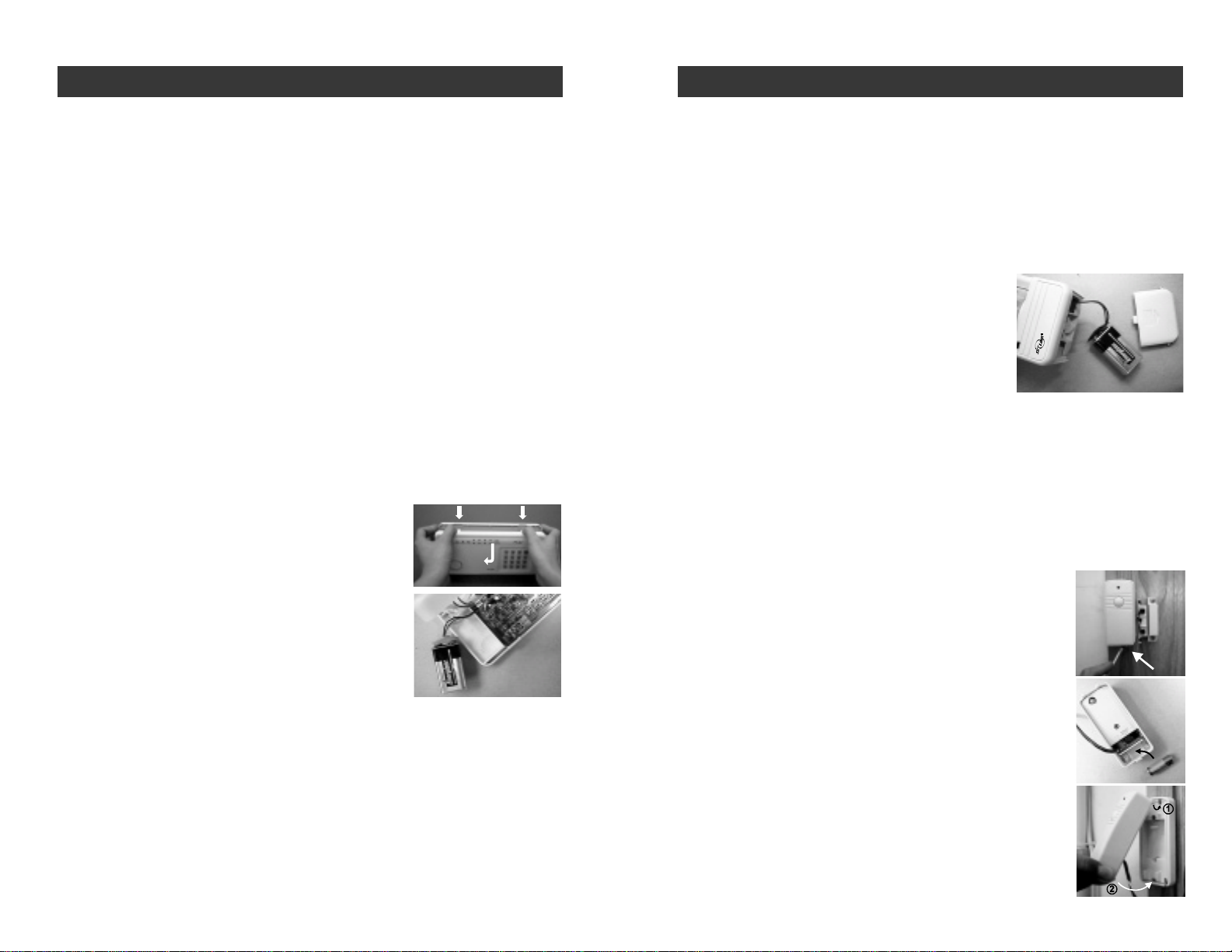
DOOR/WINDOW SENSOR BATTERY
Eachdoor/windowsensoroperatesona12voltalkalinebat-
terythat is inside the transmitter.The sensors come with the
batteriesalreadyinstalled.
To replace the battery:
1. Push on the clip at the bottom of the transmitter case
with a sharp object (such as a paper clip or pen knife)
and pull it away from the backplate.
2. Pry out the old battery from one end.
3. Push the new battery back into place. A diagram be-
side the battery well indicates which end is positive
and whichisnegative.
4. Snap the transmitter back onto the backplate.
+-
–26–
BATTERY MAINTENANCE
The SC-100 Security System comes with 5 batteries that at some point you
mayhave to replace:
1 9voltalkalinebattery for the Control Panel
1 9voltalkaline battery for the Motion Sensor
2 12voltalkalinebatteriesforthe2 Door/Window Sensors
1 12voltalkalinebatteryfortheKeychain Transmitter
Recommendation: Test you system periodically to ensure that all batteries
areworking.
CONTROL PANEL BATTERY
The Control Panel comes equipped with a backup battery in case the
electrical power is interrupted for anyreason.
When the Control Panel battery is low, the LOBATT. light goes on. Also,
when the LOBATT. light is on and if you press any key on the keypad, 10
beeps warn you that the battery needs to be changed.
To replace the Control Panel backup battery:
1. Disarm the unit.
2. Open the Control Panel case by pressing
down on the two tabs on the top edge and
pull the front forward.
3. Disconnect the old battery.
4. Connect the new battery.
5. Close the Control Panel.
Note:Toguardagainstsabotage,theControlPanelisequippedwithanemer-
gency switch that activates the alarm instantly when the case is opened.
Make sure that the unit is disarmed when you open the case or you will
activatethe alarm.
The battery life, (9 volt alkaline battery), is approximately two years if used
onlyforbackup.
Note: If the AC adapter is disconnected while the battery is replaced, the
security system will erase all the modifications that have been made and
return to the factory default. Also, your MPIN will return to 000.
SMARTHOME.COM™ 1-800-SMART-HOME 949-221-9200 http://www.smarthome.com Order #7307

KEYCHAIN TRANSMITTER BATTERY
TheKeychainTransmitter operates on a 12 volt alkaline batterywhichis
installed at the factory.
There are two screws on the back of the transmitter that holds the case
together.
To replace the Keychain Transmitter battery:
1. Undo the two screws on the back
of the transmitter.
The back will then come off.
2. Using a small screwdriver or pen
knife, pry out the old battery from
one end.
3. Place the new battery in position.
A diagram beside the battery well
indicates which end is positive
and which is negative.
4. Close the battery cover and re-
insert the two screws.
–28–
BATTERY MAINTENANCE
-+
SMARTHOME.COM™ 1-800-SMART-HOME 949-221-9200 http://www.smarthome.com Order #7307
Table of contents
Other smart home Security System manuals

Popular Security System manuals by other brands


Hella
Hella 3SL 996 139-101 installation instructions

Fire-Lite
Fire-Lite UDACT-F instruction manual

Xeos Technologies Inc.
Xeos Technologies Inc. Kilo user manual

Watchguard
Watchguard WGAP864 Quick installation guide

DyGSM
DyGSM DY-GSM10B instruction manual

Honeywell
Honeywell Frieland FGGA06 Series Quick installation guide