Smart Lifestyle SLA-R18-190D/N3A4 Instruction Manual

INSTALLATION & USER MANUAL
Air to Water Heat Pump
Water Heater
All-in-one type
Thank you very much for purchasing our product.
Before operatiing your unit, please read this manual carefully and keep it for future reference.
SMART LIFESTYLE AUSTRALIA PTY LTD
Email: [email protected]

01
If you cannot confirm that your house power supply is earthed well, please do not install the unit before carefully check it.
Please have a qualified person to check the reliable earthing connection and install the unit.
Examples of a qualified person include: Licensed plumbers, Authorized electric company personnel, and Authorized
service personnel.
SLA-R18-190D/N3A4
Part names:
Top cover
Rear Panel
Fan motor
Evaporator
Water tank
Anode rod
PTR valve
Water outlet
Cover, E-heater
Condensate drainage
Overflow
Water inlet
E-heater
Front panel
Controller
Compressor
E-box
IF THE HOT WATER SYSTEM IS NOT USED FOR TWO WEEKS OR MORE, A QUANTITY OF HIGHLY FLAMMA-
BLE HYDROGEN GAS MAY ACCUMULATE IN THE WATER HEATER. TO DISSIPATE THIS GAS SAFELY,
IT IS RECOMMENDED THAT A HOT TAP BE TURNED ON FOR SEVERAL MINUTES OR UNTIL DISCHARGE OF
GAS CEASES. USE A SINK, BASIN, OR BATH OUTLET, BUT NOT A DISHWASHER, CLOTHES WASHER, OR
OTHER APPLIANCE. DURING THISPROCEDURE, THERE MUST BE NO SMOKING, OPEN FLAME, OR ANY
ELECTRICAL APPLIANCE OPERATING NEARBY. IF HYDROGEN IS DISCHARGED THROUGH THE TAP, IT WILL
PROBABLY MAKE AN UNUSUAL SOUND AS WITH AIR ESCAPING.
WARNING - THIS APPLIANCE MAY DELIVER WATER AT A HIGH TEMPERATURE. REFER TO THE PLUMBING
CODE OF AUSTRALIA (PCA), LOCAL REQUIREMENTS AND INSTALLATION INSTRUCTIONS TO DETERMINE IF
ADDITIONAL TEMPERATURE CONTROL IS REQUIRED.
WARNING - FOR CONTINUED SAFETY OF THIS APPLIANCE IT MUST BE INSTALLED, OPERATED AND MAIN-
TAINED IN ACCORDANCE WITH THE MANUFACTURER'S INSTRUCTIONS.
WARNING
WARNING The heat pump unit requires a reliable earthing connection before usage; otherwise it
might cause death or injury.
WARNING
Installation to conform with AS/NZS 3500.4

02
SLA-R25-300D/N3D4
SLA-R25-300D/N3D4C
Contents
1. Safety information
2. Preparation of installation
3. Installations
5. Operation
6. Troubleshooting
4. Trial-running
02
07
04
11
14
12
Pages
7. Maintenance 16
8. Specifications 17
1. Safety information
Please carefully read thoroughly all of the instructions before installing or operating the unit.
Following safety symbols are very important, please carefully read and always obey all safety symbols.
CAUTION
If the warning is not heeded, it can cause death or serious injury.
WARNING
If the danger is not avoided, it will cause death or serious injury
DANGER
Top cover
Evaporator
Fan motor
Grille
Water tank
PTR valve
Cover, E-heater
Overflow
Water inlet
E-heater
Water outlet
Condensate drainage
Controller
E-box
Anode rod
Compressor
If the precaution is not taken, it may cause minor or moderate injury

03
Before cleaning, be sure to stop the operation and turn the breaker off or pull out the power supply plug. Otherwise,
an electric shock and injury may be caused.
Produced hot water temperature can reach over 50°C. It can cause severe burns instantly or death form scalds.
Children, disabled and elderly persons are at highest risk of being scalded. Feel water is necessary before bathing or
showering. So, water temperature limiting valves are recommended.
CAUTION
Do not dispose of electrical appliances as unsorted municipal waste, use separate collection
facilities. Please contact local government for information regarding the collection systems
available.
If electrical appliances are disposed of the landfills or dumps, hazardous substances can leak into
the groundwater and get into the food chain, damaging your health and well-being.
WARNING
For stationary appliances permanently connected to the fixed wiring, compliance with this requirement is considered
to be met if the instruction concerning disconnection incorporated in the fixed wiring is in accordance with AS/NZS
3000.
The unit must be earthed effectively and reliably.
A residual current operated circuit-breaker (RCCB) must be installed adjacent to the power supply.
Do not remove, cover or deface any permanent instructions, labels or the data labels from either the outside of the unit
or inside of unit panels.
Only the qualified person can perform the installation of this unit in accordance with local national regulations and this
installation manual. Improper installation may result in water leakage, electric shock or fire.
Only the qualified person can relocate, repair and maintain the unit. Improper installation and repairing may result in
water leakage, electric shock or fire.
Electric connection work should obey the instructions of local power company, local electric utility and this manual.
Never use the wire and fuse with wrong rated current, otherwise unit may breakdown and cause fire furthermore.
Do not insert fingers, rods or other objects into the air inlet or outlet. When the fan is rotating at high speed, it will cause
injury.
Never use a flammable spray such as hair spray, lacquer paint near the unit, because it may cause a fire.
The heat pump unit is not intended for use by persons (including children) with reduced physical, sensory or mental
capabilities, or lack of experience and knowledge, unless they have been given supervision or instruction concerning
use of the unit by a person responsible for their safety. Children should be supervised to ensure that they do not play
with the unit.
Once the power supply cord is damaged, it must be replaced by service agent or the manufacturer or a similarly
qualified person.
Do not dispose this unit as unsorted municipal waste. Collection of such waste separately for special treatment is
necessary.
The ground wire’s pole of socket must be grounded well, make sure that power supply socket and plug are dry and
connected well.
To check the power supply socket and plug are qualified -
Step 1: Turn on the power supply.
Step 2: Keep the unit running for a half hour.
Step 3: Turn off the power supply and plug out.
Step 4: Check whether the socket and plug is hot or not.

04
Very hot water.
Burns or injury may occur.
CAUTIONS
Heat pump water heater 1
1Installation & user manual
Item Quantity
PTR valve 1
1
1
Condensation tube
Condensation tube joint
Do not operate the unit with a wet hand; otherwise, an electric shock may be caused.
The installation height of power supply should be over 1.8m, if there is any water spattered, separate the power supply
from water.
It is normal if some water drops from the hole of PTR valve during operation. But if there is a great amount of water,
call the service agent for instruction.
After a long term use, check the unit base and fittings. If damaged, the unit may sink and result in injury.
Arrange the drain pipe to ensure smooth draining. Improper drainage work may cause wetting of the building,
furniture, etc.
Do not touch the inner parts of the controller. Do not remove the front panel. Some parts inside are dangerous to
touch, otherwise the unit malfunction may be caused.
Do not turn off the power supply. System will stop or restart heating automatically during the standby mode. A continu-
ous power supply for the unit is necessary, except service and maintenance.
If the unit has not been used for a long period of time (2 weeks or more), hydrogen gas will be produced in the water
piping system.
Hydrogen gas is extremely flammable. To reduce the risk of injury under these conditions, it is recommended that
open the hot water tap for several minutes at the kitchen sink before using any electrical appliance connected to the
hot water system. When hydrogen is present, there will probably be an unusual sound such as air escaping through
the pipe as the water begins to flow. There should be no smoking or open flame near the tap at the time it is open.
2. Preparations of installation
2.1 Transport
2.2 Packing list
In order to avoid scratch or deformation of the unit surface, please use guard boards to contacting surface.
No contact of fingers and other things with the vanes.
Do not incline the unit more than 15° to move. When install the unit, please keep the unit vertical.
Because the unit is very heavy, it needs two or more persons to carry the unit, and otherwise, it might cause
injury and damage of the unit.
Gradient limit should be more than 45°.
>45°

05
Enough space for the unit installation and maintenance should be preserved.
The surrounding of air inlet and outlet should be free from obstacles and strong wind.
The base surface should be flat, surface should be inclined no more than 2° and able to bear the weight of the unit
and suitable for installing the unit without increasing noise or vibration.
The operation noise and air flow expelled shall not affect neighbors.
No flammable gas is leaked nearby.
It is convenient for piping and wiring.
If it is installed in indoor space, it might cause indoor temperature decreased or noise. Please take preventive
measures for this.
If the unit has to be installed on a metal part of the building, make sure that the reliable electric insulation which
should meet the relevant local electric standard.
2.3 Installation site requirements
CAUTION
The ambient air temperature must also be considered when installing this unit, in heat pump mode the ambient air
temperature must be above -7°C and below 40°C. If the ambient air temperature falls outside these upper and lower
limits, the electrical elements will be activated to meet the hot water demand and the heat pump does not operate.
The unit should be located in an area not subject to freezing temperatures. The unit located in unconditioned space
(garages, basements, etc.) may require the water piping condensate piping, and drain piping to be insulated to shelter
against freezing.
When installing the unit in the following places, it may lead to the malfunction of the unit: (If it is inevitable, please
consult with the unit supplier.)
The place contains mineral oils, for example, lubricant of cutting machines.
Seaside where the air contains salt.
Hot spring area where there are some corrosive gases like sulfide gas.
Factories where the high voltage power fluctuates seriously.
Inside a car or cabin.
The place with direct sunlight and other heat supplies. If it is not avoid, please install a covering or take other
measurement.
Place where is contained by oil permeates like kitchen.
Strong electromagnetic wave surrounding.
The place filling with danger or flammable gases or materials.
The place filling with acid or alkali gases.
WARNING
The unit must be securely installed; otherwise some noise and shaking may be produced.
Confirm that there is no any obstacle around the unit.
If there is strong wind like seashore, please fix the unit in the place where is protected from the wind.

06
2.4 Maintenance space requirements
2.6 Unit dimension
2.5 Enclosed room installation
≥300mm
≥300mm ≥200mm
Controller
≥300mm
≥300mm ≥200mm
ΦD
H
D
640mm 2010mm
510mm 2175mm
H
Model
SLA-R25-300D/N3D4
SLA-R25-300D/N3D4C
SLA-R18-190D/N3A4
Top clearance is primarily a maintenance rather than operational requirement. If top clearance is reduced future
maintenance (if required) cost may increase due to need to move and then return unit to original position.
SLA-R18-190D/N3A4: the minimum area = 25m3.
SLA-R25-300D/N3D4: the minimum area = 32.5m3.
SLA-R25-300D/N3D4C: the minimum area = 32.5m3.
Note:

07
It is NECESSARY for installation to conform with AS/NZS 3500.4.
3.1 Water system piping diagram
SLA-R18-190D/N3A4
SLA-R25-300D/N3D4
SLA-R25-300D/N3D4C
3. Installations
Barrel-drain
PTR valve
Overflow
Condensate
drainage
User
Tap water
Temp. limiting
valve
(2)
Safety valve
(1)
Notes:
(1)
(2)
The drainage pipe of the safety
valve as accessories should be
connect with the atmosphere.
The temperature limiting valve is
required on the hot water usage
terminal.
Notes:
(1)
(2)
The drainage pipe of the safety
valve as accessories should be
connect with the atmosphere.
The temperature limiting valve is
required on the hot water usage
terminal.
Barrel-drain
PTR
valve
Overflow
Condensate
drainage
User
Tap water
Temp. limiting
valve
(2)
Safety valve
(1)
WARNING
In areas of water supplies with high chloride levels, water can corrode certain parts, causing them to fail.
Not suitable for heat pump units and storage tank units if the chloride content exceeds 200 mg/l.
pH is a measure of whether water is alkaline or acidic.
Heat pump units and hot water tank units with a pH value less than 6.0 are not guaranteed.
The water supply to rainwater storage tanks within urban agglomerations can be corrosive due to the dissolution of
atmospheric pollutants.
Water quality requirements (chloride and pH):
If the water heater is supplied with poor quality water, then it is necessary to install water softeners.

08
CAUTION
WARNING
Water piping system as the above figure. When install the unit at a place where outside temperature below freezing
point, the insulation must be provided for all hydraulic components.
The handle of PTR valve should be pulled out once per half a year to confirm that there is no jam of the valve. At the
same time, please take care of hot water from the valve and burning.
The outlet drain pipe should be insulated well in order to prevent water which is kept inside the pipe from freezing in
cold conditions.
The specifications of water inlet and outlet pipes as following:
SLA-R18-190D/N3A4: Internal thread (G3/4),
SLA-R25-300D/N3D4, SLA-R25-300D/N3D4C: Internal thread (G3/4).
Pipes must be heat-insulated well.
Do not dismantle the PTR valve.
Do not block off the outlet drain pipe.
It will cause explosion and injury, if do not comply with the following instruction:
Handle
Outlet
drain pipe
After water system piping work, turn on the cold water inlet valve and hot water outlet valve and start effusing the
tank. When water flow smoothly out from tap of water outlet, it means the tank is full. Please turn off all valves and
check pipeline to make sure there is without any leakage.
If the inlet water pressure is less than 0.15MPa, a pump should be installed at the water inlet pipe.
For the safety usage of water tank at the condition of water supply pressure higher than 0.65MPa, a reducing valve
should be installed at the water inlet pipe.
Condensate may be leaked from the unit if condensate drainage pipe is blocked or it operates in high humidity
environment, a drainage pan is recommended as shown as the following figure:
Unit
Drainage pan

09
3.3 Condensate water drainage
Power supply:
220-240V~, 50Hz, 1Ph
Air switch with leakage
protection
To smoothly drain the condensate water, please install the unit at a horizontal floor. At the same time, please ensure the
drainage joint is at the lowest level. Recommending the inclination angle of the unit to the ground should be no more
than 2°.
3.4 Electric connection
3.4.1 Electric wiring diagram
CAUTION
The power supply should be an independent circuit with rated voltage.
Power supply circuit should be earthed effectively. The wiring must be performed by professional technicians in
according with nation wiring regulations and the unit circuit diagram.
An all-pole disconnection device which has at least 3mm separation distance in all poles and a residual current device
(RCD) shall be incorporated in the fixed wiring according to the national rules.
Set the electric leakage protector according to the relevant electric technical standards of the state.
The power supply cord and signal cord shall be laid out neatly and properly without mutual interference or contacting
the connection pipes.
After wires connection, check it again and make sure the correctness before power on.
WARNING
In order to ensure safety, the air switch with leakage protection must be installed at the external power supply box of
the unit as shown above.
This product can be used only when the grounding is confirmed to be reliable.
Condensate
drainage
SLA-R18-190D/N3A4
≤2°
Condensate
drainage
SLA-R25-300D/N3D4
SLA-R25-300D/N3D4C
≤2°

10
3.4.2 Specifications of power supply
WARNING
The unit must be installed with a creepage breaker near the power supply and must be effectively earthed.
3.5 Installation checking
3.5.1 Location checking
3.5.2 Checking of the water system piping
Please choose the power supply cord according to the above table, and it should comply with local electric
standard.
The power supply cord model, recommanded power supply cord is H05RN-F.
PTR valve (Temperature and pressure relief valve) properly installed with a discharge pipe run to an adequate
drain and sheltered from freezing.
All piping properly installed and free of leaks.
Unit completely filled with water.
Water temperature limit valve or mixer tap (Recommanded) installed per manufacturer’s instructions.
3.5.3 Checking of condensate drain pipe
Must be located with access to an adequate drain or condensate pump.
Condensate drain lines installed and piped to an adequate drain or condensate pump.
The flooring beneath the water heater must be able to support the weight of the unit when filled with water.
Located indoors (such as a basement or garage) and in a vertical position. Sheltered from the freezing
temperatures.
Provisions made to shelter the area from water damage. Metal drain pan installed and piped to an adequate
drain.
Sufficient space to service the water heater.
Sufficient air for the heat pump to function, the water heater must be located in a space which must have
unrestricted air flow.
The unit cannot be placed into any type of closet or small enclosure.
The site location must be free from any corrosive elements in the atmosphere such as sulfur, fluorine and
chlorine. These elements are found in aerosol sprays, detergents, bleaches, cleaning solvents, air fresheners,
paint and varnish removes, refrigerants and many other commercial and household products. In addition
excessive dust and lint may affect the operation of the unit and require more frequent cleaning.
The ambient air temperature must be above -7°C and below 40°C. If the ambient air temperature falls outside
these upper and lower limits the electrical elements will be activated to meet the hot water demand.
NOTES
For optimal efficiency and service ability, the following clearances should be maintained: 200/600mm on the air inlet side ,
800mm on the air outlet side in the back.
Power supply
Min. diameter of power supply cord
Manual switch capacity / Fuse
Creepage Breaker
Earth cord
220-240V~, 1Ph, 50Hz
SLA-R18-190D/N3A4 SLA-R25-300D/N3D4 SLA-R25-300D/N3D4C
2.5mm
2
30A / 30A
30mA, ≤0.1Sec
2.5mm
2
2.5mm
2
30A / 30A
30mA, ≤0.1Sec
2.5mm
2

11
4.1 Water affusion before operation
4.2 Water emptying before operation
If the unit is used for the first time or used again after emptying the water tank, please make sure that the tank is full of
water before turning on the power.
Method: please refer to the figure.
If the unit needs cleaning, moving, etc, the water tank should be emptied.
Method: please refer to the figure.
3.5.4 Checking of the electrical connections
4. Trial-running
The water heater requires 220-240VAC for proper operation.
Wiring size and connections comply with all local applicable codes and the requirements of this manual.
Water heater and electrical supply are properly grounded.
Proper overload fuse or circuit breaker protection installed.
3.5.5 Post installation review
Understand how to use the controller to set the various parameters and functions.
Understand the importance of routine inspection/maintenance of the condensate drain pan and lines. This is
to help prevent any possible drain line blockage resulting int the condensate drain pan overflowing.
IMPORTANCE: Water coming from the plastic shroud is an indicator that both condensation drain lines may
be blocked. Immediate action is required.
Operation without water in water tank may result in the damage of the boost E-heater (electrical heater). Due to such
damage, manufacturer will not be responsible for any damages caused by this issue.
After powered on, the display lights up. Users can operate the unit through the buttons under the display.
CAUTION
When water flows out from the hot
water outlet, the tank is full. Turn
off the hot water outlet valve and
water affusion is finished.
Hot water outlet
Water affusion
Water out
Close
Open the cold water inlet valve
and the water outlet valve.
Cold water inlet Hot water outlet
Open Open
Empty
Close the cold water inlet valve, and open the
hot water outlet walve and drainpipe.
Cold water inlet
Hot water outlet
Drain nut
Close
Open
Open
After emptying, please fix the drain nut.
Drain nut
Close

12
5. Operation
4.3 Trial-running
5.1 Controller panel explanation
Checking list before commisioning:
Correct installation of the system.
Correct connection of the water and wiring.
Condensate draining smoothly well insulation work for all hydraulic part.
Correct power supply.
No air in the water pipeline and all valves opened.
Effective electric leakage protector installation.
Sufficient inlet water pressure (Between 0.15MPa and 0.65MPa).
Display area
Button area
Icons Explanations
Heat pump mode
Fast heating mode (heat
pump + boost E-heater)
Electric heater mode
Fan icon. It will be lightened,
once the fan runs.
Lock icon.
Defrost icon.
Under the defrost mode, it
will be lightened.
Under the protection of the
anti-freezing fuction, it will
be flashed.
5.2 Explanation of icons
Malfunction icon.
Timer on/Timer off icon.
Clock icon.
The setting value of water
temperature
The current value of water
temperature
Icons Explanations

13
5.3 Explanation of buttons
After the unit is powered on, the display screen will display all the icons for 3 seconds, and it will be display the regular
interface automatically.
Icons Name
Setting button
Timer button
On/Off button
Increase/up button
Decrease/down buttonMode button
Icons Name
5.3.1 On/Off button
In the unit standby state, press this button for 2 seconds to switch on the unit. When the unit is running,
press it for 2 seconds to shutdown the unit.
5.3.2 Mode button
During the unit running, press mode button, and the unit will change the operating mode as following
figure:
For these three mode, only under the heat pump mode, the boost electric heater will not be triggered.
Heat pump mode Fast heating mode Electric heater mode
5.3.3 Set button
Press the set button, the running parameters of the unit will be display. Press the and buttons
to change the parameter items.
Item
A
B
C
D
E
F
H
Explanation Range of the parameter
-20°C - 99°C
-20°C - 99°C
-20°C - 99°C
-20°C - 99°C
-20°C - 99°C
0°C - 125°C
100 - 470
Temperature of the lower water layer in tank
Temperature of the upper water layer in tank
Refrigerant temperature inside the coil
Suction temperature of the compressor
Outdoor ambient temperature
Running steps of the EXV
Discharge temperature of the compressor
5.3.4 Timer button
Press the timer button to enter the clock setting state, and the icon will be flashed. Press the
two buttons of or to setting the hours and minutes of the clock.

14
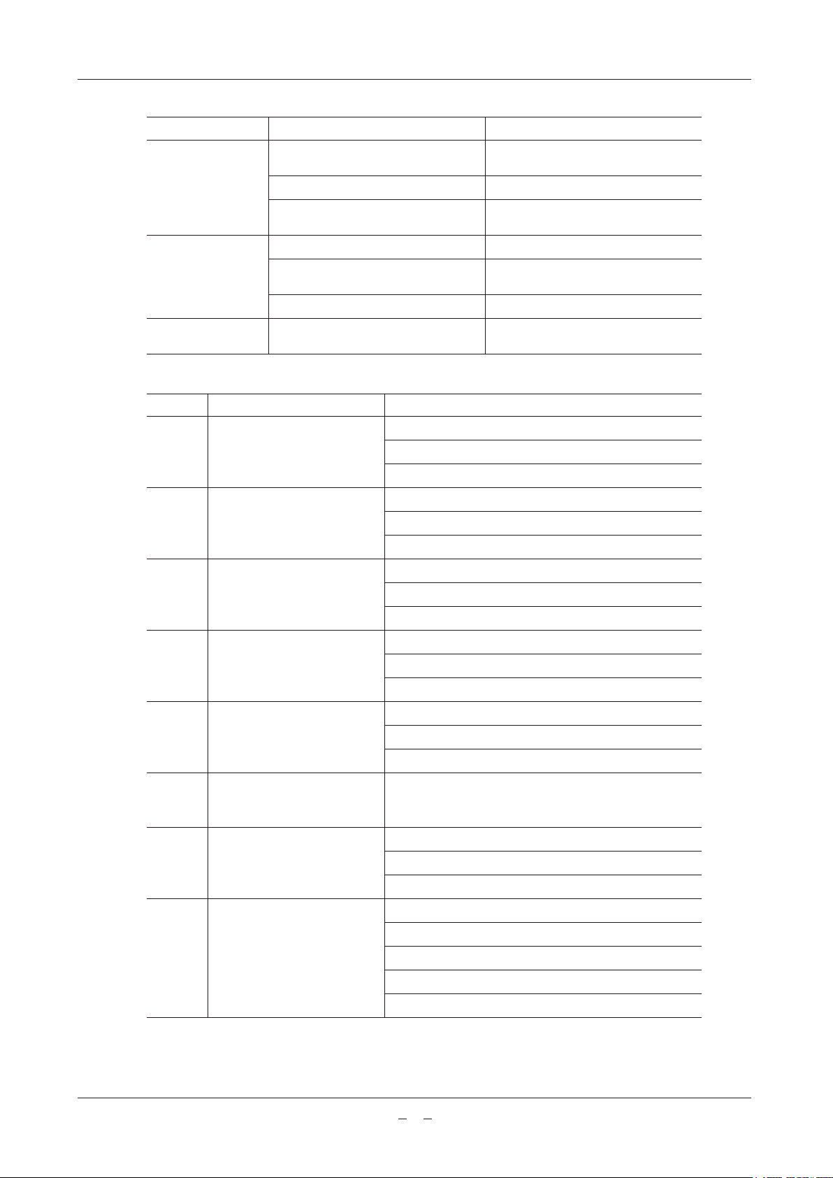
Press the timer button for 5 seconds, the timer setting state will be entered. After press it for 5 seconds, the timer
on icon and the hour of the clock will be flashed, and press or buttons to set the hour as you needed. Press
the timer button again, the minutes will be flashed. With the same steps, set the minute.
After the clock setting of the Timer on, press the timer button to confirm the setting of the timer on. After pressing
the timer button, the timer off icon will be flashed. Repeat the same steps, set the clock of the timer off. After the
timer off setting, please press the timer button again to save the timer on and off setting, and exit the setting.
When the timer on/off is already set, press the SET button, and the timer on/off will be cancelled.
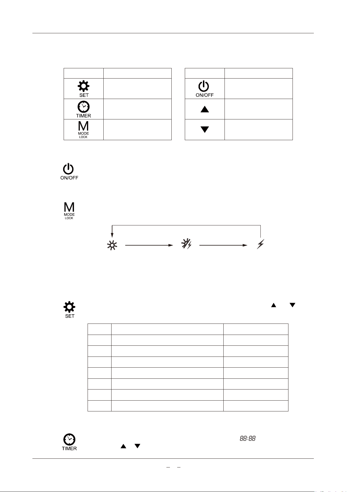
5.3.5 Increase/up button and Decrease/down button
5.3.6 Disinfect function
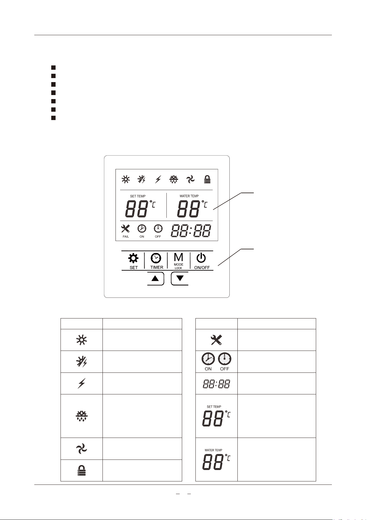
These two buttons is used when the temperature setting, the clock setting and parameters query.
When the unit is running, press these two buttons together, and all the buttons will be locked. At the same time,
the lock icon will be displayed. Press the two buttons together, the lock function will be canceled.
Under the running state of the unit, the water setting temperature can be raised by pressing the increase/up
button, while the water setting temperature can be lowered by pressing the Decrease/down button.
45% tank volume boosted to 60°C daily.
6. Troubleshooting
6.1 Non-error tips
6.2 Something about self-protection of unit
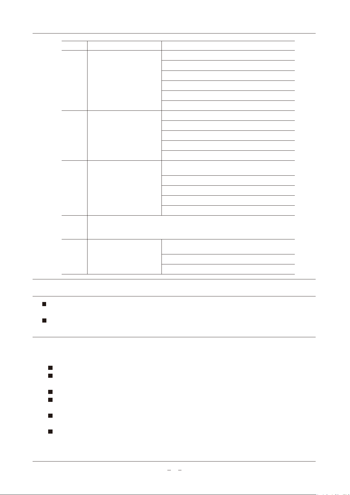
Why compressor cannot start immediatedly after setting?
Unit will wait for 3 minutes to balance the pressure of the refrigerant system before starting compressor agian. It is
a self protection logic of the unit.
Q:
A:
Why sometimes the temperature shown on the display decreased but the unit still keep off?
To avoid the unit turning on/off frequently, the unit will activate heat pump only when the water temperature in the
bottom of the tank is lower than the setting temperature.
Q:
A:
Why sometimes the unit shows ‘PA’ on the display?
The heat pump available running ambient temperature is from -7°C to 40°C. If the ambient temperature is out of
this range, the unit will show the PA to let user notice it.
Q:
A:
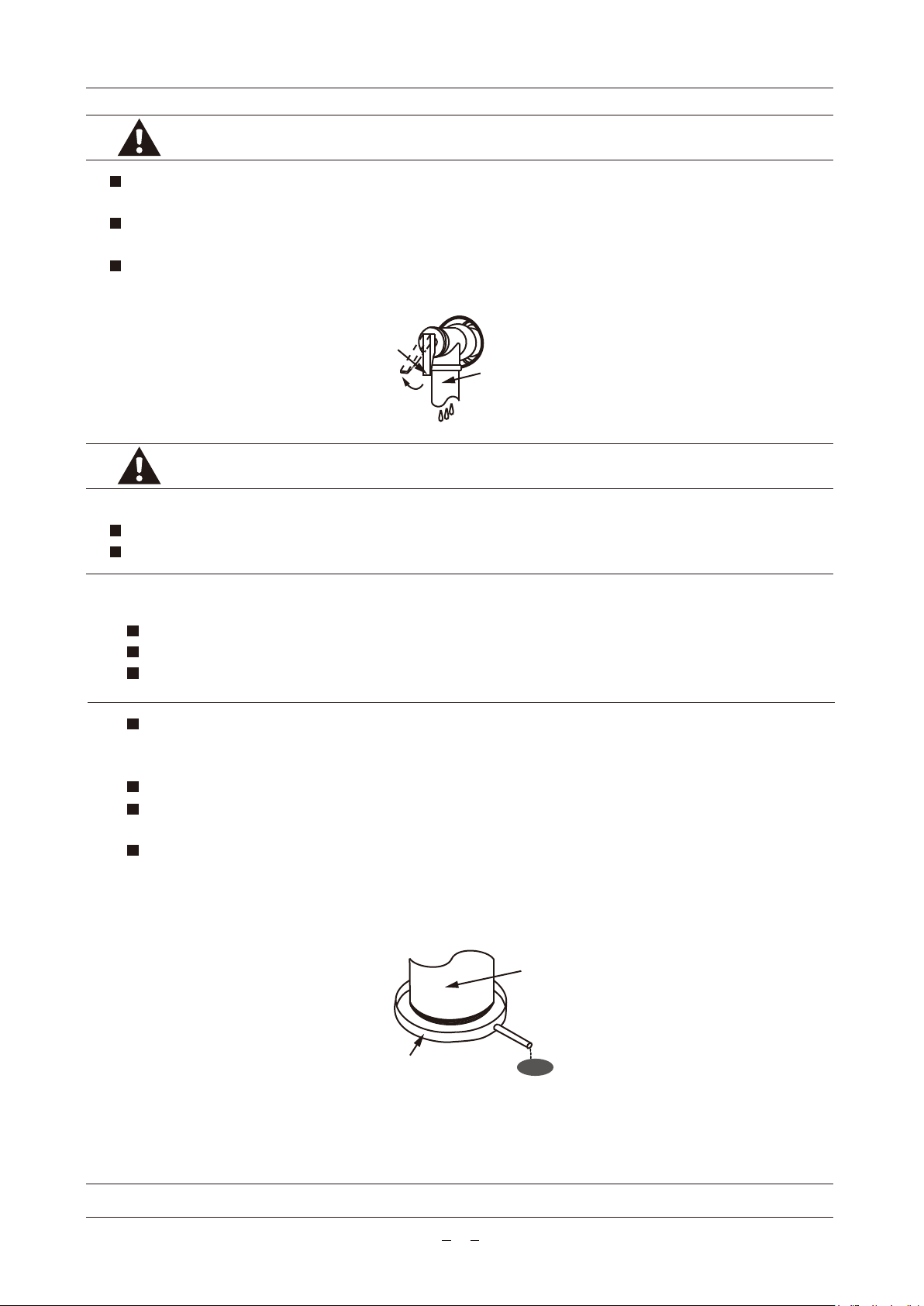
Why sometimes there is some water flowed from drainage pipe of PTR valve? (When the unit with PTR valve)
Because the water tank is pressure-bearable one, when water is heated inside the tank, water will expand, so the
pressure inside the tank will increase. If the pressure goes up more than 1.0MPa, PTR valve will activate to relief
the pressure and hot water drop will be discharged correspondingly. If water drop is continually discharged from
PTR valve drainage pipe, it is abnormal, please contact qualified staff to repair.
Q:
A:
Why sometimes the temperature shown on the dispay decreased while unit is running?
When the temperature of layer water inside the tank is much higher than the bottom part, upper hot water will be
mixed by the bottom cold water which is continually flow from the inlet tap water so that will decrease the water
temperature of upper part .
Q:
A:
When the self-protection happens, the unit will be stopped and start sef-check, and restart when the protection
resolved.
In the following circumstance, self-protection may happen:
Air inlet or outlet is blocked;
The coil is covered with too much dust;
Incorrect power supply (Exceeding the range of 220-240V).

15
6.3 Error phenomenon shooting
6.4 Error code shooting table
Error phenomenon
Cold water tapped
out and display
screen extiguished
No hot water
tapped out
Water leakage Check and reseal all joints.
Bad connection between power
supply plug and socket. Plug in again.
Set the water temperature higher.
Contact service center.
Setting water temperature is too low.
Public water supply is ceased. Wait for water supply to recover.
Cold water inlet valve is closed. Open the water inlet valve.
Cold water inlet pressure is too low.
(less than 0.15MPa)
Hydraulic pipeline joints are not
sealed well.
Wait for inlet water pressure
increase.
Temperature sensor or PCB is
broken.
Possible reason Solution
Code
P01
P02
P03
P04
P05
P06
P07
Check connection to sensor
Replace sensor if broken
Replace PCB if broken
Check connection to sensor
Replace sensor if broken
Replace PCB if broken
Lower water temperature
sensor error
Upper water temperature
sensor error
Coil temperature sensor error
Suction temperature sensor
error
Discharge temperature
sensor error
E01 High pressure protection
Outdoor ambient temperature
sensor error
Anti-freezing protection
This protection is normal. The unit which is under standby
state will trigger this protection when the water tank
sensor detects the water temperature is lower than 5°C.
Description Corrective action
Check connection to sensor
Replace sensor if broken
Replace PCB if broken
Check connection to sensor
Replace sensor if broken
Replace PCB if broken
Check connection to sensor
Replace sensor if broken
Replace PCB if broken
Check connection to sensor
Replace sensor if broken
Replace PCB if broken
Check connection to switch
Replace switch if broken
Check refrigerant system isn’t blocked
Check the refrigerant volume isn’t too high

16
Code
E02
E03
E04
PA
Check the low pressure swtich connection is not well.
Check if pressure switch is broken.
Check if refrigerant system is block.
Check for leakage in refrigerant system to repair
Check refrigerant volume isn’t too low
Replace PCB if broken
Low pressure protection
Over-heat protection
(optional)
It is normal and no need repair. The heat pump available running ambient temperature is
from -7°C to 40°C. If the ambient temperature is out of this range, the unit will show the
PA to let user notice it. During this period, the boost electrical heater can be used.
E08 Communication error
Over-high protection of
discharge temperature
Description Corrective action
Check the connector
Replace protector if broken
Replace E-heater if broken.
Replace water temperature sensors if broken.
Replace PCB if broken
Check if temperature sensor connection is not well.
Check if discharge temperature sensor is broken.
Check if the refrigerant system is block.
Check if the refrigerant is too much.
Replace PCB if broken
Check connection between PCB and controller if its
broken
Replace the controller is broken.
Replace the PCB if its block.
The diagnostic codes listed above are the most common. If a diagnostic code not listed above is displayed, please
contact residential technical assistance.
If any of E01/E02/E04 continuously appear 3 times within 30 minutes, the unit will consider it as heat pump system
error, and the unit will stop running. The unit will not run until the power supply is reset.
NOTE
7. Maintenance
7.1 Maintenance
Check the connection between power supply plug, socket and groud wiring regularly.
In some cold area (blow 0°C), if the unit will be stopped for a long time, all the water should be released in case of
freezing of inner tank and damage of boost electrical heater.
It is recommended to clean the inner tank and boost E-heater every half year to keep an efficient performance.
Check the anode rod every half year and change it, if it has been used out. For more details, please contact the
supplier or the after-sale service.
It is recommended to set a lower temperature to decrease the heat release, prevent scale and save energy if the
outlet water volume is sufficient.
Before shutting the system off for a long time, please:
Shut off the power supply;
Release all the water in the water tank and the pipeline. Close all the valves;

17
8. Specifications
7.2 How to change the anode rod
Turn off the power supply, and turn off the water inlet valve.
Open hot water tap, and decrease the pressure of the inner tank.
Open the drainage valve, and drain out the water, until there are no water flow out.
Remove the cover / panel of top part, and take out the anode rod.
Replace it with a new one, and make sure effective sealed.
Open cold water inlet tap untill water flows out from outlet tap then close water outlet tap.
Power on and restart the unit.
Check the inner components regularly.
7.3 Recommended regular maintenance table
Item
1
2
3
4
Every 6 months Replace it if it has been used out.
Every 6 months
Every 6 months
Every 1 year
Clean the tank.
Operate the hander of the PTR valve to
ensure that water can be flowed out.
Clean E-heater.
anode rod
Inner tank
Boost E-heater
PTR valve
Model SLA-R18-190D/N3A4 SLA-R25-300D/N3D4
SLA-R25-300D/N3D4C
Checking content Check frequency Action
If water does not flow freely when operating the hander, replace
PTR valve with a new one.
Power supply
Running ambient air Temp.
Rated water supply pressure
PTR valve setting
Heating capacity
Rated power input (Heat pump)
Max. input power / current
Outlet water Temp.
Water connection size
Operation pressure (High / Low)
IP data
220-240V~, 50Hz, 1Ph
-7°C - 40°C
800kPa
850kPa
465W
1700W
2615W / 11.89A
35°C - 65°C
G3/4’’
4.4MPa / 0.6MPa
IPX4
-7°C - 40°C
800kPa
850kPa
610W
2500W
2863W / 13.02A
35°C - 65°C
G3/4’’
4.4MPa / 0.6MPa
IPX4
The dates of rated power input (Heat pump) and heating capacity are based on the condition:
Inlet water from 14°C to 55°C; Air 19°CDB/15°CWB.


[UI-SCO01-10d]
Other manuals for SLA-R18-190D/N3A4
1
This manual suits for next models
2
Table of contents
Popular Water Heater manuals by other brands

Gorenje
Gorenje TGR 30 NGC6 Instructions for use

Bradford White
Bradford White M-1-40S6BN Installation and operating instruction manual

PVI Industries
PVI Industries QuickDraw Installation & maintenance manual

Baxi
Baxi STS 150 2.0 LP Installer/User

State Water Heaters
State Water Heaters 184671-000 instruction manual

Hyco
Hyco Ara IN30 Product instruction manual