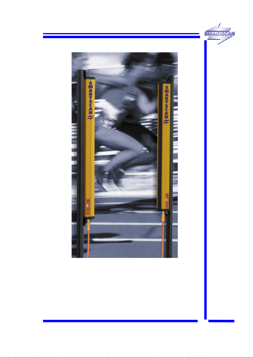
SMART-SCAN 7000 Series User manual

7000 SERIES
SMARTSCAN INFORMATION
Smartscan Ltd, Pywell Road, CORBY, NN17 5XJ, UK Tel: +44 (0) 1536 401313,
SS-7K
SEP02
7000 SERIES
LIGHT CURTAINS
HANDBOOK
ISSUE 1

7000 SERIES

7000 SERIES
CONTENTS Page
INTRODUCTION 3
INTERFACE 5
SPECIFICATION 9
LIGHT CURTAINS 30mm DETECTION CAPABILITY 10
LIGHT CURTAINS 70mm DETECTION CAPABILITY 11
LIGHT CURTAINS FOR PERIMETER GUARDING 12
INTERCONNECT CABLES 12
CONTROL MODULE 13
ACCESSORIES 15
SAFETY SYSTEM SOLUTIONS 22
INSTALLATION SHEET 24
APPENDIX 1 44
APPENDIX 2 50
www.smartscan.com
7000 SERIES LIGHT CURTAINS

7000 SERIES
.

7000 SERIES
7000 Series Safety Light Curtains
The 7000 Series offers a wide range of models for finger, hand, leg and
body protection.
The 7000 system from Smartscan is compact in size and provides
many sophisticated control features as standard, including: 2 and 3
beam floating blanking for press and press brake applications, external
test and auto or latched reset control options. A muting function is also
provided.
The 7000 Series meets the very highest standards for safety - 3rd Party
Approved for compliance to the latest European Standards including BS
EN 61496-1 and BS IEC 61496-2. Rated as a Type 4 device the 7000
Series is suitable for ALL machine applications including those
categorised ‘high risk’.
INTRODUCTION
3

7000 SERIES
Typical machine safeguarding applications include:
qPress brakes
qMechanical presses
qGuillotines
qProduction lines
qRobots
7000 Series light curtains comply with British and International Safety
Standards for Light Curtains BS EN 61496-1 & BS IEC 61496-2 Type 4.
They are normally used in situations which demand a high level of
safety integrity, where the risk assessment for the safety related parts of
a control system, as indicated in BS EN 954-1, determines a
requirement up to and including Category 4 control equipment.
qEC Type Examined
qFor high risk applications - Category 4
qSimple installation and alignment
qUp to 15m scanning range
qTwo year manufacturers warranty
Features
qMuting (model dependent)
qDynamic floating blanking
qDiagnostic and status indicators
qSelectable range setting
qSelectable auto or manual start / restart interlocks
qSafety monitoring feedback loop (External Device Monitoring) EDM
qAuxiliary relay switching contacts
qMute lamp output with monitoring (model dependent)
INTRODUCTION
4

7000 SERIES
Safety Outputs OSSD1 and OSSD2 (F1) - Two independent electronic
switches provide the fail-safe outputs for connection to the machine
control system. Connections are at terminals J6/10 and J6/11 on the
control module. Outputs 'on' = 24V. Outputs 'off' = 0V maximum
switching current = 1A.
LED indicators mounted on the control module show the status of the
OSSD switches.
Safety Relay Outputs (F2) - a number of 7000 Series control module
types have on-board cross-monitored output switching relays. With
these models the electronic outputs are connected via links to the
inputs of the relay coils. Link electronic output switches to relay inputs
J6/10 to J6/6 and J6/11 to J6/7. The output relay switching contacts are
on terminals J6/4, J6/8 and J6/5, J6/9. Maximum switching power
110V, 2A.
Status Relay Outputs (F3/F4) - Relay switching contacts are provided
for guard status indication. The changeover output contacts from this
relay are non-safety. The status relay activates when the safety outputs
(F1) turn ON and de-activates when the safety outputs turn OFF.
Terminal connections are as follows: N/O contact J6/1, N/C contact
J6/3, Common 6J2. Maximum switching power 24V, 1A.
Mode (F5) - The mode setting switch is mounted on the control module.
The switch enables modes to be selected to suit the specific machine
applications. The dip switches can be set to provide the following
modes: 1) No interlock. 2) Start interlock. 3) Restart interlock. 4) Start
and Restart interlock. For settings refer to the table, Fig. O.
INTERFACE
5
Green LED’s ON = OSSD1 and OSSD2 active ON
Red LED’s ON = OSSD1 and OSSD2 inactive OFF
Warning: When using the mute function select only mode 3
Restart interlock or, mode 4 Start/Restart interlock.
Warning: Mode switch changes have no effect until all electrical
power is removed from the control module and then re-
applied.
Warning: When setting up the light curtain, ensure that mode 1
No interlock is selected.

7000 SERIES
Range (F6) - The range setting switch is mounted in the control
module. The switch enables light curtain scanning ranges to be
selected to suit a specific application. The dip switches can be set to
provide the following ranges: 1) 0.5m to 1m 2) 1m to 4m 3) 4m to 15m.
For settings refer to Fig. N.
Mute indicator (F7) - A number of machine types require that a
monitored mute indicator be fitted when the light curtain is in a muted
condition, e.g. presses and press brakes. The 7000 system is fitted
with mute monitoring circuits and outputs for connection of a suitable
indicator. The indicator lamp must be 12V, 2.2 Watt to satisfy the
monitoring requirements. If no lamp or a lamp of incorrect power is
fitted at terminals J1/13 and J1/14 then the light curtain will not mute.
If light curtain muting is used but a mute indicator is not required for a
particular application connect a 78 Ohm 2.2 Watt resistor across
terminals J1/13 and J1/14.
Mute input (F8) - The complimentary input is provided at terminals
J1/11 and J1/12 for connection of suitable switching signals for muting
the light curtain. When both signals are active ON, and providing a
suitable mute lamp or ballast resistor has been fitted across terminals
J1/13 and J1/14 then the light curtain will mute, e.g. the guard output
switches will not respond to an interruption of the light curtain.
The mute switching signals must have the following polarity:
Mute signal A at terminal J1/11 = +24V DC
Mute signal B at terminal J1/12 = 0V DC
INTERFACE
6
Warning: Range switch changes have no effect until all electrical
power is removed from the control module and then re-
applied.
Warning: When using the mute function select only mode 3
Restart interlock or, mode 4 Start/Restart interlock.
Note: Signals must be applied to both mute inputs at J1/11 and J1/12
within 200ms of each other. If this time is exceeded the system
will go to a lockout condition.

7000 SERIES
Start/restart (F9) - A suitable push button or key switch with a N/O
contact must be fitted across terminals J6/12 and J6/13 to reset the light
curtain when in the following modes; Start interlock, Restart interlock,
Start + Restart interlock.
Floating blanking (F10) - Floating blanking allows selected areas of
the detection zone to be disabled. The function is particularly useful for
those applications where, for example, a work piece is obstructing the
light curtain or possibly moving up and down within the curtain.
The 7000 Series has the capability of 1, 2 and 3 beam floating blanking,
offering much increased flexibility.
Floating blanking can be selected to allow one, two or three beam
obstructions within the light curtain to be ignored. The obstruction can
move or ‘float’ within the detection zone without initiating a stop signal
providing the obstruction does not interrupt more than the selected
number of ‘floating’ beams. If one beam blanking is selected, any
single beam in the light curtain can be blocked without the guard
outputs de-energising. If two beam floating blanking is selected any two
beam obstruction can be ignored. With three beam blanking any three
beams blocked will be ignored. The interrupted beams do not have to
be adjacent to each other.
Beam blanking is selected by connecting appropriate input signals to
the following terminals on the control module: +24V at J1/7, 0V at J1/8,
+24V at J1/9 and 0V at J1/10. For connection details refer to Fig. Q.
INTERFACE
7
Note: The input signal must be applied within 200ms of each other. If
this time is exceeded the system will go to a lockout condition.
The signals may be applied during operation of the guard and
will take immediate effect. This feature can be used to increase
the integrity of a guarding application (partial muting).
Note: Beam blanking increases the size of object which is guaranteed
to be detected by the light curtain. (An increased ODC). When
selecting 1, 2 or 3 beam floating blanking the worst case ODC
should always be taken into account during the risk assessment
process. Check the position of the light curtain in relation to the
nearest danger point is in line with the requirements of
European Standard BS EN 999.

7000 SERIES
Monitoring (F11) - External Device Monitoring (EDM) inputs are
provided. If external relays are used it may be necessary to ensure the
relays respond each time the light curtain is interrupted.
If the monitoring function is not required for a particular application it is
necessary to link terminal J1/2 to J1/4 (0V) and J1/1 to J1/3 (+24V). If
the links are not fitted the light curtain control will go into a lockout
condition.
Power supply (F12) - Use a regulated supply +24V DC, 1.5A ±10%
Protect the +24V input with a 1.5A fuse (see note below). Terminal
connections: J6/16 = +24V, J6/15 = L- V and J6/14 = Ground.
Interlock indicators (F13/F16) - Yellow LED interlock indicators are
provided on both the transmitter unit and in the control module. When
the LED’s are illuminated the 7000 system is in a lockout condition e.g.
latched in the 'off' state by interlock function F5.
Guard ‘clear’ indicator (F14) - A green LED indicator mounted on the
transmitter unit illuminates when the light curtain is clear and
operational ON.
Guard ‘block’ indicator (F15) - A red LED indicator mounted on the
transmitter unit illuminates when the light curtain is blocked and non-
operational OFF.
Safety relay input (F17) - Some 7000 Series control module types
have on-board cross monitored output switching relays. With these
models the electronic outputs are connected via links to the inputs of
the relays. Link output switches to relay inputs J6/10 to J6/6 and J6/11
to J6/7. The two output relay switching contacts are on terminals J6/4,
J6/8 and J6/5, J6/9. Maximum switching power 110V, 2A.
INTERFACE
8
Note: Both monitoring signals must be applied within 200ms of each
other. If the time is exceeded the system will go to a lockout
condition.
Note: OSSD current is an addition to the control units quiescent
current (no load) For example if the electronic OSSD’s are
consuming the maximum rated current OSSD1 = 1A & OSSD2
= 1A then the input fuse must be increased as follows 1A + 1A
+ 1.5A (quiescent current). Therefore fuse rating = 3.5A

7000 SERIES
7000 Series Light Curtains
Number of beams 2 -112
Object detection 30mm, 70mm & Perimeter Guarding
Detection zone 176mm to 2072mm (model dependent)
Range 0.5 - 15m (model dependent)
Light type Infra-Red 880nm
Response time (relay output) 25ms
Operating temperature 0°C to + 50°C
Light curtain enclosure IP66/7 (HxWxD) Hx44x56mm
Control module enclosure IP65 (HxWxD) 108x224x65mm
Power supply requirement 24V DC 2.5 A ± 10% reg
Current consumption 1.5A (NO LOAD)
Light curtain connectors M12 8 Way IP67
Finish Polyester powder coated (yellow) RAL 1006
Classification BS EN 61496-1
BS IEC 61496-2 Type 4
BS EN 954-1 Category 4
Warranty Two Years
INPUTS
Safety monitoring (EDM) Complementary inputs
Start, restart interlock 4 separate modes (selectable)
Floating blanking 1, 2 or 3 beam blanking (selectable)
Muting Complementary inputs
OUTPUTS
Safety output relays 2 x N/O fail safe contacts, each rated at
110V AC, 2A
Status output relay 1 x change over contact (non - safety), rated at
24V, 1A
Mute lamp output 12V DC 2.2 Watt (monitored)
Status indication Status & condition LED’s on controller
& light curtain
SPECIFICATION
9
FM27829
Certificate Number: CK/KID/091/99
Report Number:
8/005027
Certificate Number: AV EC 1456-A
amtri veritas Type Examined

7000 SERIES
Light Curtains 30mm Detection Capability Range 15m
Model
number Number
of beams Detection zone
(K) mm Weight
(Tx + Rx) Kg
072-150 8176 1.0
072-151 16 321 1.5
072-152 24 467 2.1
072-153 32 613 2.7
072-154 40 759 3.2
072-155 48 905 3.8
072-156 56 1051 4.1
072-157 64 1196 4.7
072-158 72 1306 5.5
072-159 80 1488 6.0
072-160 88 1634 6.6
072-161 96 1780 7.1
072-162 104 1926 7.4
072-163 112 2072 8.2
LIGHT CURTAINS
10

7000 SERIES
Light Curtains 70mm Detection Capability Range 15m
Model
number Number
of beams Detection zone
(K) mm Weight
(Tx + Rx) Kg
072-201 4303 1.5
072-203 8536 2.3
072-204 10 653 2.7
072-205 12 769 3.1
072-206 16 1002 4.0
072-207 20 1235 4.8
072-208 24 1469 5.6
072-209 30 1818 6.7
LIGHT CURTAINS
11

7000 SERIES
Light Curtains Perimeter Guarding Range 15m
Model
number Beam
Pitch Overall length
(M) mm Weight
(Tx + Rx) Kg
072-250 2 @ 500mm 585 2.3
072-251 3 @ 450mm 930 3.3
072-252 4 @ 400mm 1175 4.0
Interconnect Cables
Model
number Length m
071-303 5
071-306 20
LIGHT CURTAINS
12

7000 SERIES
Control Module IP65
Mode
number Description
072-103 Relay output (IP65)
072-107 Relay output with mute (IP65)
CONTROL MODULES
13
Warning: Do not use inside control enclosures where
temperature may exceed rating.
FM27829
Certificate Number: CK/KID/091/99
Report Number:
8/005027
Certificate Number: AV EC 1456-A
amtri veritas Type Examined

7000 SERIES

7000 SERIES
Mirror Units
Two or three sides of a machine can be safeguarded with a single light
curtain by using mirrors to deflect the light curtain’s infra-red beams.
(See appendix 2 for installation guidance).
The Smartscan mirror system provides a sturdy floor mounting kit
together with an aluminium column for mounting the mirror. The mirror
assembly simply slots onto the column and can be adjusted to the
height required for the application.
The special mounting stand enables the mirror unit to be rotated
through 360 degrees while also allowing full adjustment in all axes.
ACCESSORIES
15
Note: Mirrors cause a reduction in optical efficiency, reducing the effective
range of the light curtain. Refer to appendix 2 for guidance.

7000 SERIES
Range of the
light curtain Maximum range
through 1 mirror Maximum range
through 2 mirrors
0.5m – 15m 9m 6m
Mirrors Model
number Description
044-252 600mm x 110mm wide mirror unit
044-249 900mm x 110mm wide mirror unit
044-250 1200mm x 110mm wide mirror unit
044-253 1400mm x 110mm wide mirror unit
Column & Floor Stand
Model
number Description
044-256 1.1m aluminium universal mounting column
044-257 1.3m aluminium universal mounting column
044-258 1.6m aluminium universal mounting column
044-247 1.8m aluminium universal mounting column
044-262 2.0m aluminium universal mounting column
044-248 Floor stand
ACCESSORIES
16
Note: A universal mounting column and floor stand is required for each
mirror unit.
Note: Mirror length must be a minimum of 100mm longer than the
overall length of the light curtain to be installed.

7000 SERIES
Power Supply
If a suitable stabilised 24V DC,
2.5A power supply is not
available the following unit is
recommended.
Model
number Description
071-050 Power supply Input 85 - 264V AC
Output 24V DC, 2.5A
Features
qHigh reliability
qHigh efficiency, low working temp
qBuilt in EMI filter, low ripple noise
qCompact size, lightweight
qShort circuit, over load, over voltage protection
qApprovals: UL, TUV, CB, and CE
Specification
Type Switch mode
Input Voltage 85 - 264V AC
Input frequency 47-63HZ
Inrush current Cold start, 24A, 115V & 50A, 230V
Output voltage/current rating 24V DC, 2.5A
Operating temperature 0°C to 50°C
Storage temperature -10°C to +70°C
Connection 5P/9.5mm pitch terminal block
Enclosure 160x98x38mm Din rail mounting
Weight 0.5 Kg
ACCESSORIES
17

7000 SERIES
Mounting Stands
Designed to accommodate our range of safety light curtains.
The Adjustable Stand (50mm x 50mm) offers the user a flexible
mounting option. The stand has adjustable brackets that allow the
safety light curtain to be mounted at different positions to suit a specific
application.
The Channel Stand allows the user to mount the safety light curtain
inside a protective housing. This provides protection on three sides to
give a more robust installation. Channel stands would typically be used
where the safety light curtain is at risk of damage from fork lift truck
operations.
ACCESSORIES
18
This manual suits for next models
25
Table of contents
Other SMART-SCAN Lighting Equipment manuals