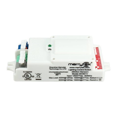
Smart temp Viking RS-SSD User manual

Viking Smart Sensor RS-SSD Manual
Version 3.0
Manual version 1.2

Page 2of 8
Thank you for the purchase of the Viking Smart Sensor RS-SSD V3.0. This
advanced sensor will provide the user with better access to the Viking’s many
functions that will improve the user experience.
The new Smart Sensor is compatible with all Viking firmware versions,
however many of the new functions detailed below will only be compatible
on Vikings with firmware version 4.0 or above. This sensor is fully backwards
compatible with older SMT-920 Viking firmware and can be used as a
replacement sensor.
Sensor Functions
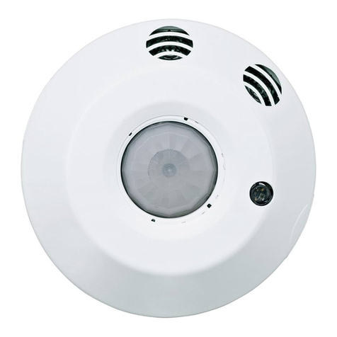
The RS-SSD temperature and humidity sensor has been designed to permit
the user to see and control room temperature. Further, if enabled by the
installer, the RD-SSD version 3.0 will permit the control of several other
functions such as setpoint adjustments or the ability to turn the air
conditioning on or off.
Turning the Air Conditioning On or Off
If enabled by the installer, this function will permit
you to force the air conditioning off, overriding the
SMT-920 Viking time clock function or when you
wish to control the air conditioning manually. To force the air conditioning
off, press and hold the Mode Select button for 2 seconds.

Page 3of 8
Using the After Hours Run Function
If enabled by the installer, this function will
permit you to start the after hours run timer so
your air conditioning can be operated outside of
normal operating hours for a pre-set time with the
Auto Off timer. The After-Hours function is only available outside of normal
operating hours. To use the after hours run function, simply tap the Mode
Select button when the text “After Hours”is shown.
Adjusting Heating and Cooling Mode
If enabled by the installer, you will be permitted to
select Heating Only mode where no cooling will be
called, Cooling Only mode where no heating will be called or Auto mode
where the heating and cooling will be controlled. Simply tap the Mode Select
button to toggle through all available modes.
Adjusting Set Temperature
If enabled by the installer, you will be permitted to adjust the set
temperature by tapping the temperature Up/Down buttons for the
available heating or cooling modes. These setpoints shown on the
RS-SSD version 3.0 sensor adjust the setpoints stored in the SMT-
920 Viking controller. If Single Setpoint adjustment mode is
enabled, then the setpoint adjustment will apply equally to both
the heating and cooling setpoints that have been set in the SMT-
920 Viking.
Fan Mode Adjustment
If enabled by the installer, you will be permitted to
adjust the mode of the air conditioning Fan.
Available modes will be shown and adjustable by tapping the Fan button.

Page 4of 8
Installing the Sensor
The wiring overview shown (below) indicates how each sensor in the
network of sensors is wired. S1, S2, S3 & S4 on the sensor is wired to S1, S2,
S3 & S4 on the SMT-920 Viking. Each sensor is fitted with a set of switches
on the printed circuit board as shown in the diagram below. These switches
set the address of the sensor. It doesn’t matter what address you select but
no two sensors connected to any one SMT-920 Viking should share the same
network address.
Do not set all DIP switches ON
Up to 15 Smart Sensors can be installed on
to any single SMT-920 Viking. The
individual Smart Sensor will show its local temperature and humidity
however the SMT-920 Viking will control to the average temperature of all
16 sensors. Further, Hi or Low
select can be used if set by the
installer within the Viking installer
menu.

Page 5of 8
Remote Temperature Sensor
The RS-SSD room temperature sensor can be disabled and a
standard Smart Temp 2 wire remote sensor (RS-01/02) can be
used should you wish to measure room temperature at a
different location to the RS-SSD version 3.0 location. Wire the
RS-01/02 into the RS-SSD “TT” terminals.
Do not enable Display Only mode if you
intend to use 2 wire remote sensors
connected to the RS-SSD.
Installer Options Menu
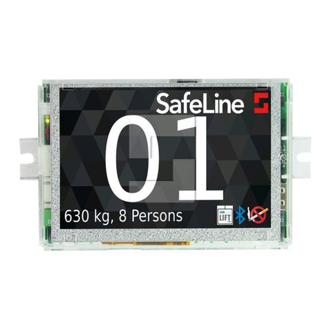
The RS-SSD has an Installer Options
menu that permits you to control or adjust various sensor functions.
To Enter the Installer Menu
Press and hold the lower right corner of the
LCD until the display changes and shows you
the number “15". Use the Up/Down button
to adjust the display to show “21", the
factory default PIN or your previously set
PIN if changed from the factory default.
Tap the lower right corner to enter the Installer menu. If the PIN is correct
you will enter the menu. If you enter an incorrect PIN you will be exited from
this menu.

Page 6of 8
Tap the lower right corner to advance through the menu options, tap the
lower left corner to step backwards through the menu. Tap the arrow
pointing up on the left of the display to exit the Installer menu and use the
Up/Down buttons on the right of the display to adjust the menu options.
Installer Options Menu
AH
After Hours Run Period - This function is used as a countdown timer when the
SMT-920 Viking is in Manual mode or an after hours run timer when the SMT-
920 Viking time clock function is used.
Adjustable from 0 to 12.0 hours in 0.5 hour increments. Default 2 hours.
Setting this value to OFF disables the after hours run timer function.
OO
On –Off Function - Permits the user to turn the SMT-920 Viking on or off.
In Programmable mode –This function overrides the program to OFF. (If air
conditioning is not required for some time for example)
In Manual mode - This function acts as a manual ON / OFF.
Press and hold the Mode Select button for 2 seconds to initiate this function.
nn
User Modes Available - Sets the mode(s) available to the user by pressing the
Mode Select button.
0 = Off or Auto mode (unable to select heating only or cooling only mode)
(Default)
1 = Off or Heat only
2 = Off or Cool only
3 = Off, Heat or Cool
4 = Off, Heat, Cool, Auto

Page 7of 8
St
Set Temp Mode Enable - This function permits the user to adjust the set
temperature for the selected modes.
Off = Set temperature adjustments are not permitted (Default)
1 = Single Setpoint mode - The sensor will show the average of the active heating
and cooling setpoints and adjust both setpoints equally. (If heat set is 20 and cool
set is 22, the RS-SSD sensor will show a setpoint of 21. Adjusting the setpoint on
the RS-SSD will adjust both heating and cooling setpoints by the same amount.
2 = 2 Setpoint mode - The heating and cooling setpoints can be independently
adjusted.
HL
Heating Setpoint Limit - Sets the maximum possible Heat Setpoint
CL
Cooling Setpoint Limit - Sets the minimum possible Cool Setpoint
RS
Sensor Speed of Response - This option adjusts the temperature sensor
response time changes in room temperature.
VS = Very slow S = Slow Nor = Normal Fst = Fast VF= Very Fast
SC
Temperature Sensor Calibration - Permits a +/- 5.0⁰C adjustment of room
temperature sensor value.
rH
RH Sensor Calibration - Permits a +/- 20 % adjustment of relative humidity
sensor value.
BL
Backlight Brightness
0 =Off
1 = Low
2= Medium
3 = High
4 = Always ON
DI
Display Only Mode - If enabled, this function disables the RS-SSD sensor for
temperature and humidity. This sensor will now only display the values (or
average value if multiple sensors are used) reported by other Smart Sensors
connected to the same SMT-920 Viking.
Pn
PIN - This is the number required to enter the Installer menu. Adjust with caution
as a forgotten PIN will require factory reset. (Default is 21)
Bp
Beeper - Enables or disables the audible beep when buttons are pressed.

Page 8of 8
Smart Temp Australia P/L
Unit 20 /1488 Ferntree Gully Rd
Knoxfield Victoria
Australia 3180
+61 397630094
www.smarttemp.com.au
[email protected]om.au
Copyright Smart Temp Australia P/L 2020
Table of contents
