Energetech Solar PB5000 User manual
POWER BANKS STORAGE SYSTEM
User Manual
Version: 2.0
PB5000 (51.2V 100AH-5.12Kwh)
PB7000 (51.2V 150AH-7.68Kwh)
PB10000 (51.2V 200AH-10.24Kwh)
For On / Off Hybrid Solar Storage System

- 1 -
Contents
1. Safety Precautions ....................................................................................................................................... - 2 -
1.1. Before Connecting .................................................................................................................................................. - 2 -
1.2. During operation ..................................................................................................................................................... - 2 -
2. Battery Specifications ................................................................................................................................. - 3 -
3. Introduction to the battery ........................................................................................................................... - 4 -
3.1. Key Features .......................................................................................................................................................... - 4 -
3.2. Interface Introduction .............................................................................................................................................. - 4 -
3.3. SOC Indicator & Status Indicator Guides ................................................................................................................. - 5 -
3.4. Connectors ............................................................................................................................................................. - 7 -
3.5. Wake Up button ...................................................................................................................................................... - 7 -
3.6. Display function instruction ...................................................................................................................................... - 7 -
3.6.1. Reference of real figure .................................................................................................................................... - 7 -
3.6.2. Screen Display ................................................................................................................................................. - 7 -
3.6.3. Functional Specifications .................................................................................................................................. - 8 -
4. Safe handling guide ................................................................................................................................... - 11 -
4.1. System Diagram ................................................................................................................................................... - 11 -
4.2. Tools ..................................................................................................................................................................... - 11 -
4.3. Safety Gear ........................................................................................................................................................... - 11 -
5. Installation .................................................................................................................................................. - 12 -
5.1. Inventory of items .................................................................................................................................................. - 12 -
5.2. Installation Location .............................................................................................................................................. - 13 -
5.2.1. Minimum clearances ....................................................................................................................................... - 13 -
5.3. Installing the Battery Pack ..................................................................................................................................... - 14 -
5.3.1. Mounting to a wall .......................................................................................................................................... - 14 -
5.4. Parallel use of battery............................................................................................................................................ - 16 -
5.4.1. Parallel use of battery ( All off grid solar inverters ) ........................................................................................ - 16 -
5.4.2. Parallel use of Energetec battery on Canbus /RS485( All hybrid on-off grid solar inverters) ............................. - 18 -
5.4.3. ADS guide Line .............................................................................................................................................. - 18 -
6. Product Warranty ....................................................................................................................................... - 21 -
6.1. .............................................................................................................................................................................. - 21 -
6.2. .............................................................................................................................................................................. - 21 -
6.3. .............................................................................................................................................................................. - 21 -
6.4. Factory Warranty Scope ........................................................................................................................................ - 21 -
6.5. Warranty conditions .............................................................................................................................................. - 21 -

- 2 -
1.Safety Precautions
It is very important and necessary to read the user manual carefully before installing or using the
battery. Failure to follow any of the instructions or warnings in this document can result in
electrical shock, serious injury, death, or may damage the battery and the whole system.
If the battery is stored for a prolonged time, it is requirement that they are charged every three to
six months, and the SOC should be no less than 80%.
The battery needs to be recharged within 12 hours, after fully discharging.
Do not expose cable outside.
All battery terminals must be disconnected before maintenance.
Do not use cleaning solvents to clean the battery.
Do not expose the battery to flammable or harsh chemicals or vapors.
Do not paint any part of the battery, include any internal or external components.
Do not connect battery with PV solar wiring directly.
Any foreign object is prohibited to be inserted into any part of the battery.
Any warranty claims are excluded for direct or indirect damage due to items above.
1.1.Before Connecting
After unpacking, please check the battery and packing list first, if the battery is damaged or spare
parts are missing, please contact the dealer.
Before installation, be sure to cut off the grid power and make sure the battery is in the turned-off
mode;
Wiring must be correct, do not mix-connect the positive and negative cables, and ensure no short
circuit with the external device;
It is prohibited to connect the battery with AC power directly;
The embedded BMS in the battery is designed for 48VDC, please DO NOT connect battery
in series;
It is prohibited to connect the battery with different type of battery;
Please ensure the electrical parameters of battery system are compatible to inverter;
Keep the battery away from fire or water.
1.2.During operation
If the battery system needs to be moved or repaired, the power must be cut off first and the
battery is completely shutdown;
It is prohibited to connect the battery with different type of battery;
It is prohibited to put the batteries working with faulty or incompatible inverter;
In case of fire, only dry powder fire extinguisher can be used, liquid fire extinguishers are
prohibited;
Please do not open, repair or disassemble the battery. We do not undertake any consequences
or related responsibility due to violation of safety operation or violating of design, production and
equipment safety standards.

- 3 -
2.Battery Specifications
Battery Specifications
Model No PB5000 PB7000 PB10000
Nominal Parameters
Voltage 51.2V 51.2V 51.2V
Capacity 100Ah 150Ah 200Ah
Energy 5.12KwH 7.68KwH 10.24KwH
Dimensions (L x W x H) 680 x480 x180(220)mm 680 x480 x180(220)mm 680x480x180(220)mm
Weight 60.50kg 78.0 kg 105.5kg
Basic Parameters
Life time(25°C) 20 years
Life cycles(80% DOD, 25°C) 6000 Cycles
Storage time / temperature 5 months @ 25°C; 3 months @ 35°C; 1 month @ 45°C
Operation temperature -20°C to 60°C @60+/-25% Relative Humidity
Storage temperature 0°C to 45°C @60+/-25% Relative Humidity
Lithium Battery Standard IEC62133, IEC62619,UN38.3,ROHS,CE-EMC,MSDS
Enclosure protection rating IP21
Electrical Parameters
Operation voltage 51.2 Vdc 51.2 Vdc 51.2 Vdc
Max. charging voltage 56Vdc 56Vdc 56 Vdc
Cut-off Discharge Voltage 46 Vdc 46 V dc 46 Vdc
Max. charging and discharging
current 150A(7680W) 150A(7680W) 200A(10120W)

- 4 -
3.Introduction to the battery
3.1.Key Features
LiFePO4 composition – provides exceptional safety and longevity
High safety and reliability
6,000cycles/ 20 years’ service life
Consistent performance over wide temperature range
Wall-mounted, convenient installation
Integrated state-of-the-art BMS to manage and monitor battery information including voltage,
current and temperature as well as balance cell charging/discharging rates
10 years’ warranty
3.2.Interface Introduction
This section details the interface functions of front and back panel..
Front interface:
- 5 -
No
. Description Silk-screen Remark
1
D
ial switch
ADS
Set the address
2
CAN port
CAN
CAN port
3
RS485 port
RS485
RS485 port
4
RS485 port
RS485
RS485 port
5
Port Reset
button RST For reset the batter
6
Bracket
7
Switch
OFF/ON
Normal close
8 Anderson
connector - +
Input
/Output
terminal
9
Handle
10
LED
ALM
Alarm indicator
11
LED
RUN
Operation indicator
12
LED
CAPACITY
Capacity indicator
13
LCD
14
LCD KEY
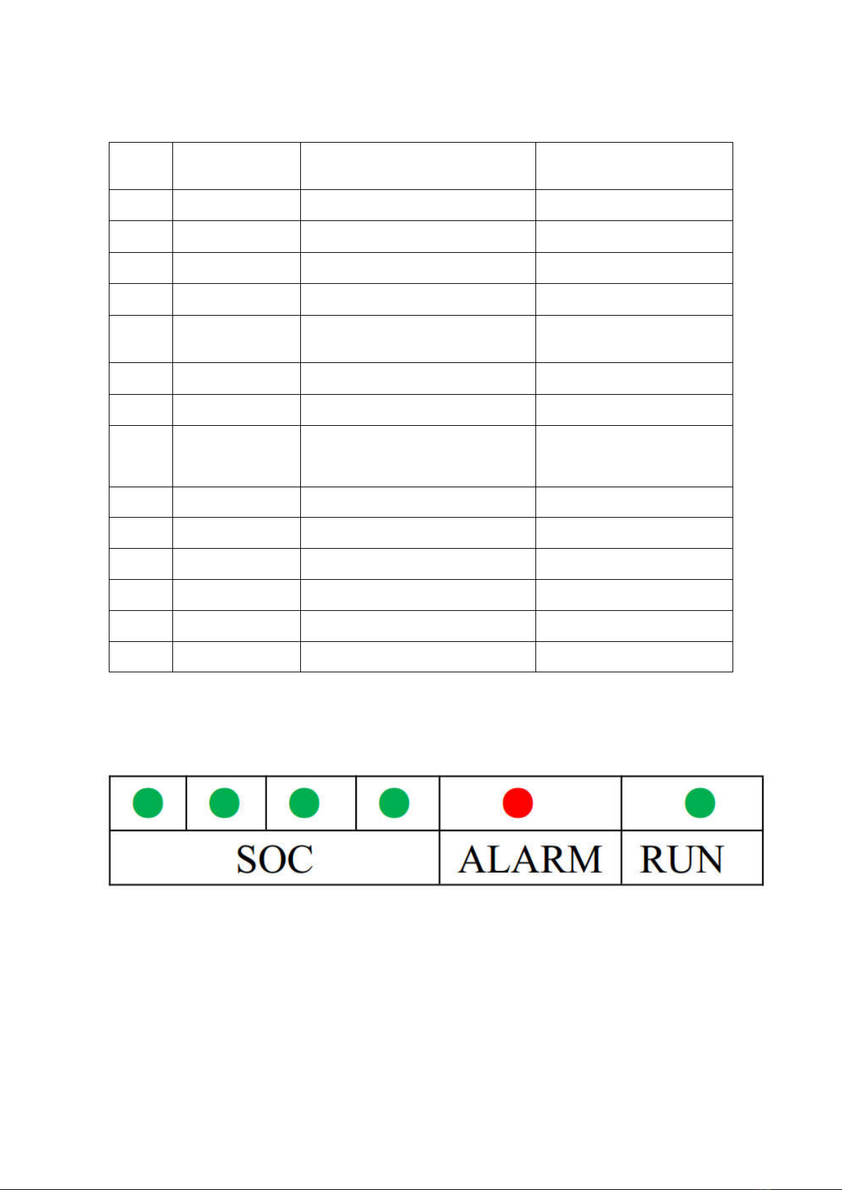
3.3.SOC Indicator & Status Indicator Guides
Chart 1: Battery Status

- 6 -
Chart 2: Battery Capacity
Chart 3: Battery status

- 7 -
3.4.Connectors
Charge / Discharge connectors: to connect the positive pole (+) and negative pole (-) from the
battery to the inverter via DC isolator.
Canbus Active communication portal between battery and inverter.
USB To RS485: to get dynamic monitoring data of the battery from upper computer.
Address: Reserved Address portal for multiple parallel connections.
3.5.Wake Up button
Battery On: When battery is shut down, press this RST button for 6 seconds. It is activated
when the LED lights flicker from RUN light to the lowest capacity indicator.
Battery off: When battery is activated, press this button for 6 seconds. It will be shut down
when the LED lights flicker from lowest capacity indicator to RUN light.
3.6.Display function instruction
3.6.1.Screen Display

- 8 -
3.6.2.Functional Specifications
Interface introduction
Main menu page
Electricity/dormancy activated, will show the welcome screen, press the MENU button to enter
the main menu page. As shown in the figure below:
Battery cells state
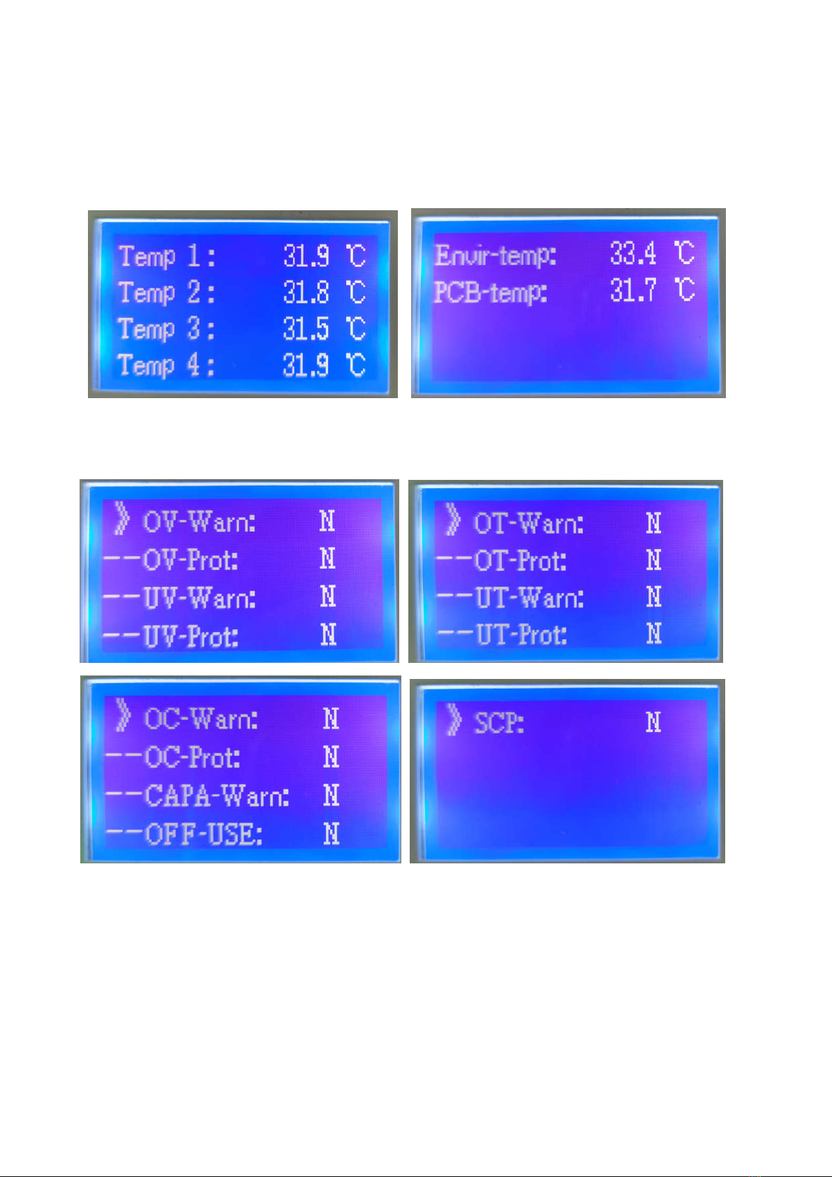
- 9 -
Battery temperature
Battery Warning
- 10 -
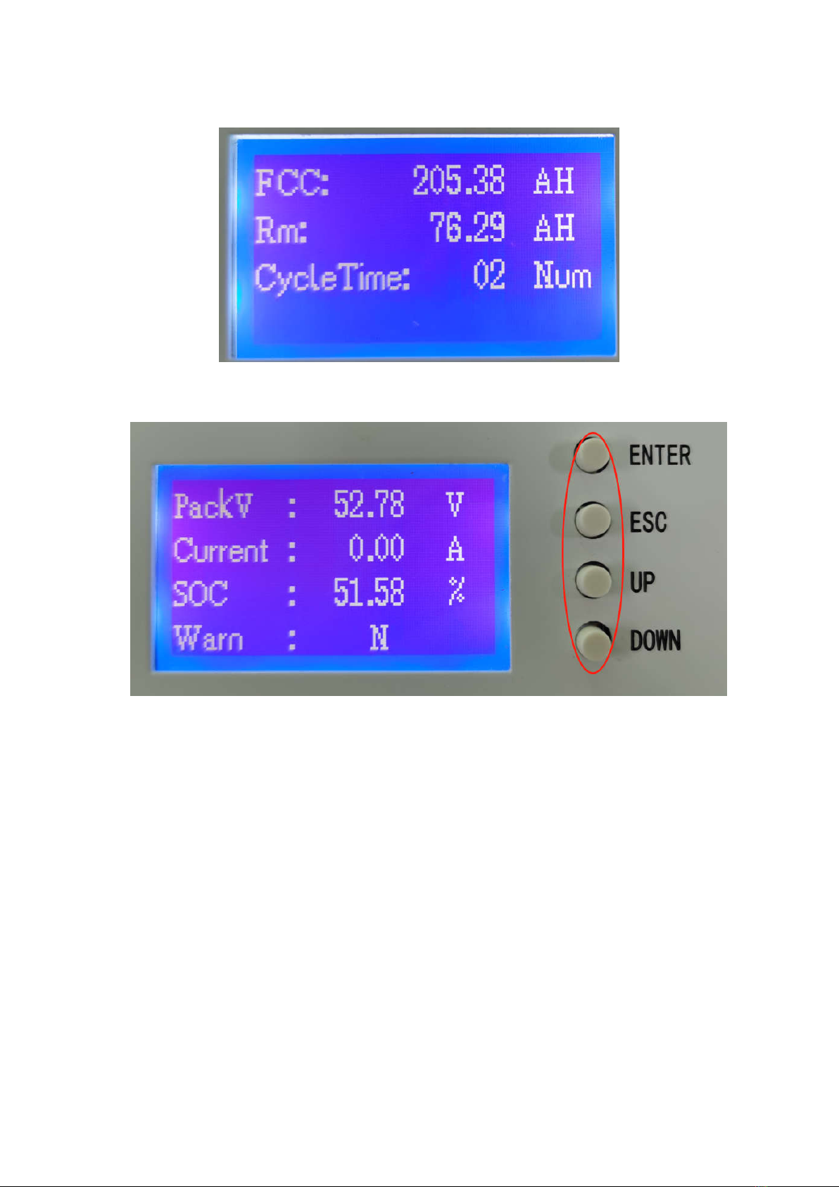
Battery Capacity
Key description
1) SW1----NEMU ,SW2----ENTER ,SW3----UP ,SW4----DOWN
2) Each item is “》”or“--”as a beginning,among them“》”shows the current cursor position,
press UP or DOWN key can move the cursor position;with“》”end of the project,the
content of the said project has not shown, press ENTER key can enter the corresponding
page.
3) Press ESC key can be returned at the next higher level directory;In any position, press
NEMU key can return to the main menu page.
4) In a dormant state, press any key, can activate the screen.
Dormancy/shutdown
Under normal operation condition, with no keystrokes 1 minutes later, system will enter a
state of dormancy/shutdown.
Shutdown/dormancy state,press any key,screen can be activated.

- 11 -
4.Safe handling guide
4.1.System Diagram
4.2.Tools
The following tools are required to install the battery pack:
Wire cutter
Crimping Modular Plier
Screw Driver
NOTE
Use properly insulated tools to prevent accidental electric shock or short circuits.
If insulated tools are not available, cover the entire exposed metal surfaces of the available
tools, except their tips, with electrical tape.
4.3.Safety Gear
It is recommended to wear the following safety gear when dealing with the battery pack:
Insulated gloves
Safety goggles
Safety shoes
- 12 -
5.Installation
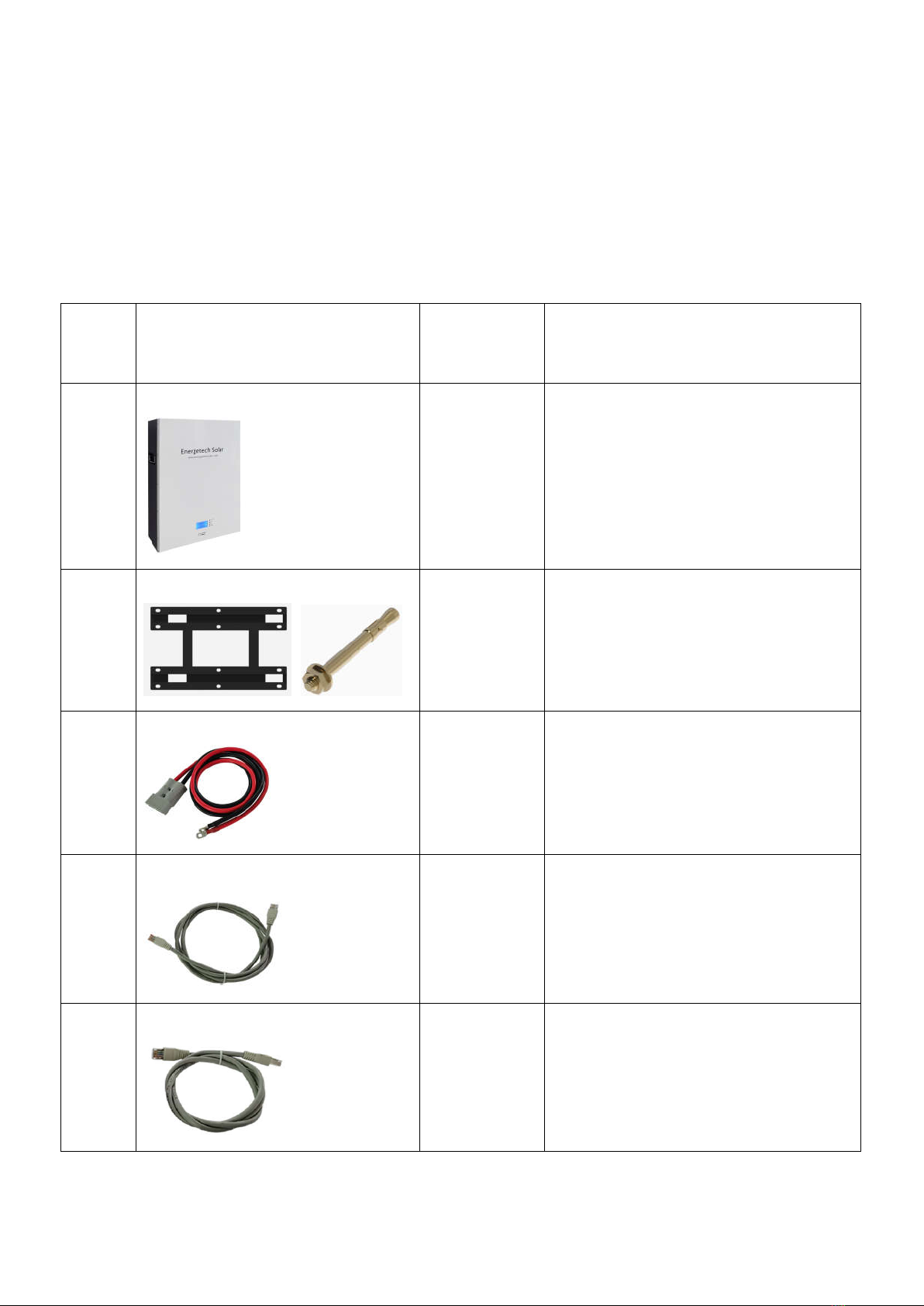
5.1.Inventory of items
Thoroughly inspect the packaging upon receipt of goods. If there is any item missing or if there is any
damage to the external packaging or to the unit itself upon unpacking, please contact us immediately.
NO. Item Quantity Specification
1 Battery Pack
1 PC 5.12KWH/7.68KWH/10.12KWH
2 Wall mounted Bracket and Screws
1 SET One Bracket and 12pcs screws.
3 Power Cable
1 SET 35mm2 ( 4AWG) Black , Red
L 2.0 meter
Anderson 350A Standard+ M8 Termial
4 Canbus Cable
1 PC Battery canbus port to Inverter Canbus
port
L : 1.5 meter
5 Parallel com cable
1 PC Battery com port to Battery com port for
parallel 16pcs at max
L: 1.0 meter

- 13 -
5.2.Installation Location
Make sure that the installation location meets the following conditions:
The installation site must be suitable for the size and weight of the battery.
Must be installed on a firm surface to sustain the weight of battery.
The area is water proof.
There are no flammable or explosive materials in proximity
The ambient temperature is within the range from 0°C to 45°C.
The temperature and humidity is maintained at a constant level.
There is minimal dust and dirt in the area.
Installation must be vertical or tilted backwards by maximum 15° - avoid forward or sideway
stilt.
CAUTION
If the ambient temperature is outside the operating range, the battery pack stops operating to protect
itself. The optimal temperature range for the battery pack to operate is 0°C to 45°C. Frequent exposure
to harsh temperatures may deteriorate the performance and life of the battery pack.
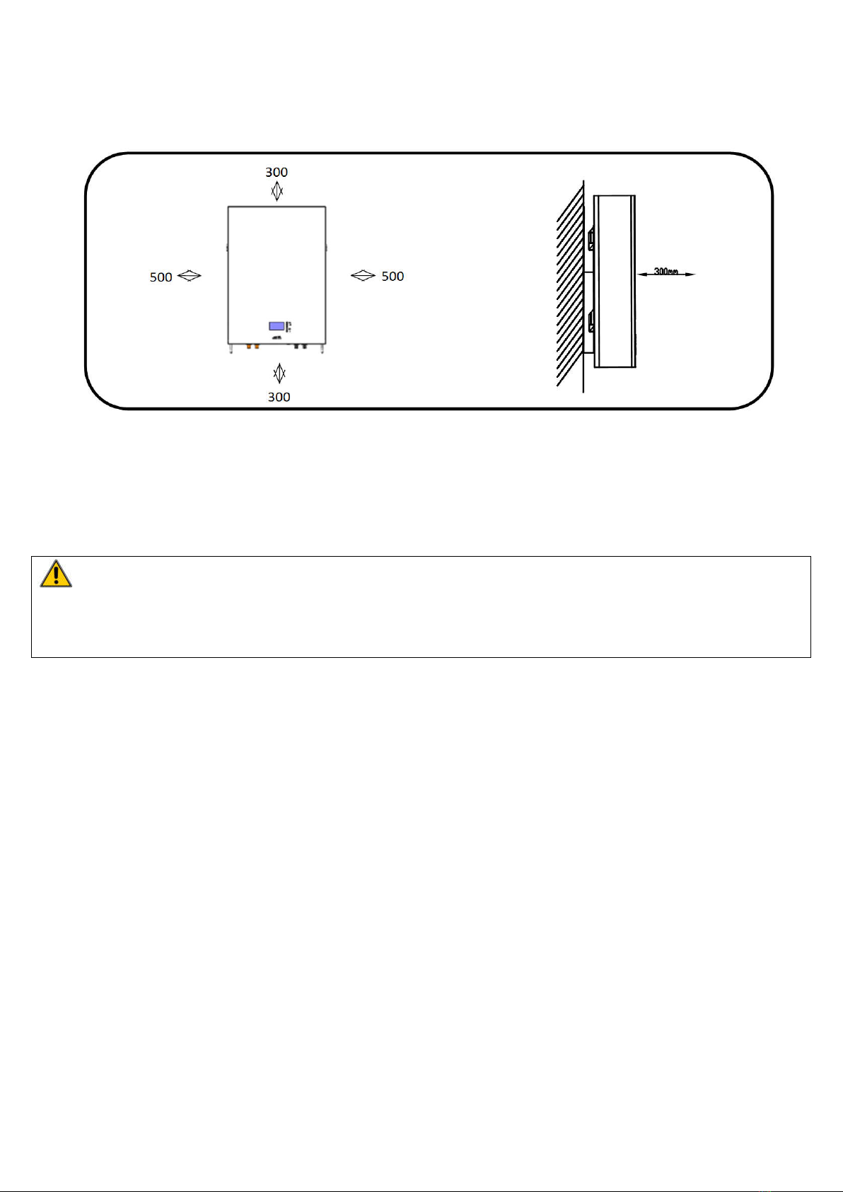
5.2.1.Minimum clearances
Observe the minimum clearances to walls, other batteries or objects as shown in the diagram and
picture below in order to guarantee sufficient heat dissipation
Direction Minimum clearance (mm)
Above 300
Below 300
Sides 500
Front 300
- 14 -
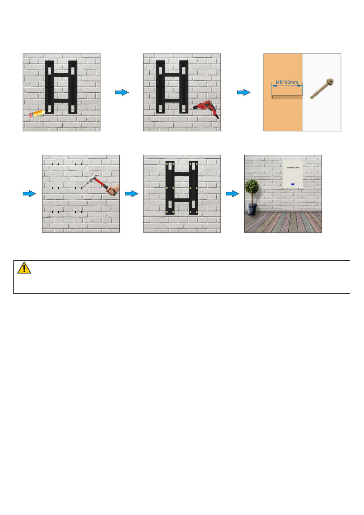
5.3.Installing the Battery Pack
5.3.1.Mounting to a wall
WARNING
In order to avoid electrical shock or other injury, inspect existing electronic or plumbing installations
before drilling holes.
The battery is heavy, please handle with care to avoid damage to the product or injury to the installer.
1.Choose suitable firm wall with thickness greater than 80mm.
2.Use the mounting frame as a template, mark the hole position.
3.Drill 8 holes according to the hole position, it is ø10 with depth 60mm.
4.Hammer the M8 screws to the above holes, and screw the nut. Note: Do not position screws
flush to the wall - leave 10 to 20 mm exposed.
5.Fix the mounting frame to the 8 screws.
6.Raise the battery a little higher than the mounting frame whilst maintaining the balance of the
battery. Hang the battery on the frame through the match hooks.
- 15 -
WARNING
Falling equipment can cause serious or even fatal injury: never mount the inverter on the bracket unless
you are sure that the mounting frame is firmly mounted on the wall after thorough checking.
- 16 -
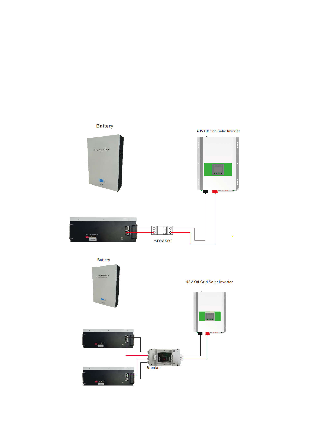
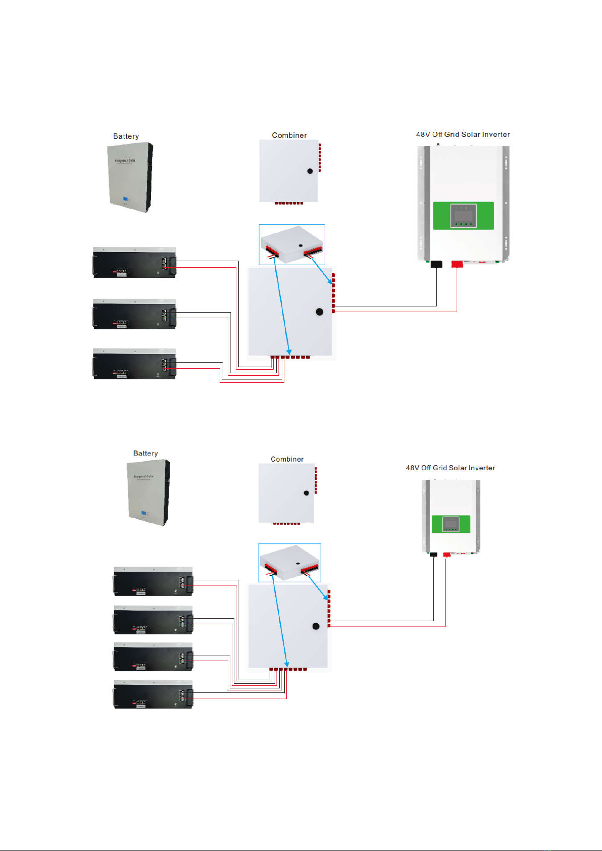
5.4 Parallel use of battery
5.4.1 Parallel use of battery ( All off grid solar inverters )
Energetech Solar powerbank battery is a smart battery to match all off grid solar inverter ( 48VDC) types.
When the battery needs to be used in parallel, the maximum connection is 16 units, but we recommend
2-4 units according to application. When connecting with off grid 48VDC solar inverters, it does not
need to add Canbus/RS485 communication cables with inverters, if inverter brand factory does
not have Canbus/RS485 port, just plug and play use.
One pcs connect diagram
Two pcs connect diagram
- 17 -
Three pcs connect diagram
Four pcs connect diagram
NOTE : IF YOU NEED MORE PARALLEL DETAILS, PLEASE CONSULT WITH ENERGTECH SOLAR SALES
ASAP.

- 18 -
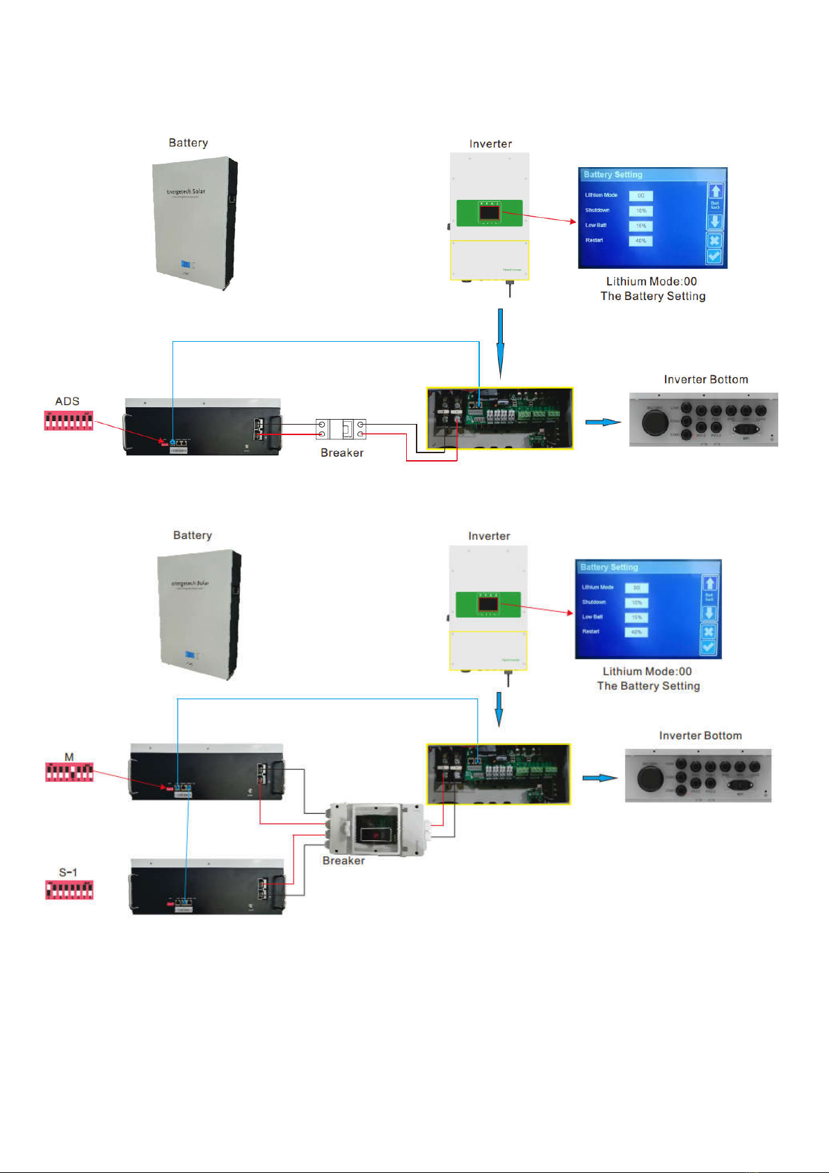
5.4.2 Parallel use of Energetech Solar battery on Canbus
(hybrid on-off grid solar inverters)
When the battery needs to be used in parallel, the maximum connection is 16 units ( Canbus ) with
Energetech hybrid solar inverter, but we recommend to use 2-4 units according to application. The
application needs power and communication connections as below, choose suitable parallel power
cables and related connectors.
ADS guide Line
If you start to connect Energetch hybrid inverter, make sure you should consult with
Energetech sales manager before connection. If the hybrid inverter is not from Energetech
factory brand, please specify related hybrid on-off grid inverter brand with Energetech
sales managers.
- 19 -
One pcs connect diagram
Two pcs connect diagram
This manual suits for next models
2
Table of contents
Popular Accessories manuals by other brands


Silvercrest
Silvercrest HG01910B Assembly, operating and safety instructions

Abus
Abus SHHA10000 manual

coolbreeze
coolbreeze CB4900 user manual

Steelcraft
Steelcraft One 2 instruction manual

ThinkGizmos
ThinkGizmos XN012 AERO ADVANTAGE user manual

Biospherical Instruments Inc
Biospherical Instruments Inc QSR-2200 user manual

MRHANDSFREE
MRHANDSFREE Portable Power charger 5200 mAh Pure Edition user manual

Aqua Medic
Aqua Medic Titan 150 Operation manual

Chef's Choice
Chef's Choice Pronto Diamond Hone 464 manual

SUP’AIR
SUP’AIR SKYPPER FR user manual

Pegasus Astro
Pegasus Astro ULTIMATE POWERBOX V2 product manual

Tripp Lite
Tripp Lite UPB-10K0-1U1CQ owner's manual