SMART Audio CAS-340 User manual

SMART Audio™
CAS-340 and CAS-360
Classroom amplification systems
System administrator’s and user’s guide

Product registration
If you register your SMART product, we’ll notify you of new features and software upgrades.
Register online at smarttech.com/registration.
Keep the following information available in case you need to contact SMART Support.
Serial number:
Date of purchase:
FCC warning
This equipment has been tested and found to comply with the limits for a Class A digital device, pursuant to Part 15 of the FCC Rules. These limits are designed to provide
reasonable protection against harmful interference when the equipment is operated in a commercial environment. This equipment generates, uses and can radiate radio
frequency energy and, if not installed and used in accordance with the manufacturer’s instructions, may cause harmful interference to radio communications. Operation of
this equipment in a residential area is likely to cause harmful interference in which case the user will be required to correct the interference at his own expense.
Trademark notice
SMART Audio, SMART Board, SMART Notebook, smarttech, the SMART logo and all SMART taglines are trademarks or registered trademarks of SMART Technologies
ULC in the U.S. and/or other countries. Blu-ray is a trademark of the Blu-ray Disc Association. All other third-party product and company names may be trademarks of their
respective owners.
Copyright notice
© 2011 SMART Technologies ULC. All rights reserved. No part of this publication may be reproduced, transmitted, transcribed, stored in a retrieval system or translated
into any language in any form by any means without the prior written consent of SMART Technologies ULC. Information in this manual is subject to change without notice
and does not represent a commitment on the part of SMART.
Patents pending.
April 11, 2011

Important information for your
classroom amplification system
W W A R N I N G
lFailure to follow the installation instructions shipped with your SMART product could result in
personal injury and damage to the product which may not be covered by your warranty.
lTo reduce the risk of fire or electric shock, do not expose the SMART product to rain or
moisture.
lEnsure that any cables extending across the floor to your SMART product are properly
bundled and marked to avoid a trip hazard.
lDon’t open or disassemble the SMART product. You risk electrical shock from the high
voltage inside the casing. Opening the casing also voids your warranty.
lIf your SMART product requires replacement parts, make sure the service technician uses
replacement parts specified by SMART Technologies or parts with the same characteristics
as the original.
lTo reduce the risk associated with leaking batteries:
odo not leave the battery in the product for an extended period
odo not heat, disassemble, or short the battery, or expose it to fire or high temperature
oavoid eye and skin contact if batteries have leaked
odispose of exhausted batteries and product components in accordance with applicable
regulations
lDo not charge the battery with any power adapter other than the one supplied. Do not charge
other battery types in your SMART product with the supplied power adapter. Both of these
actions can cause damage to the product and can cause a fire or personal injury.
If the SMART product becomes excessively warm or emits an unusual smell while the
battery is recharging, immediately disconnect the power adapter from the power outlet and
turn the product off.
iii

lDo not use your SMART Audio™ classroom amplification system in a facility control system
or any other environment that requires extremely high reliability, or where the use of a
wireless device can cause interference. The product can interfere with other electronic
devices or cause them to malfunction, or other wireless devices may interfere with the
product or cause it to malfunction. Where use is prohibited, turn off the product. SMART
Technologies does not accept any liability for damages.
lEnsure your ceiling or ceiling tiles are strong enough to support the ceiling-mounted product
components and use tethers if provided or required. Failure to securely install components
might lead to components falling which can cause personal injury and product damage that
may not be covered by your warranty. Refer to product documentation to find component
weights.
lEnsure the installation of your SMART product meets local building codes and regulations.
C C A U T I O N
lAvoid setting up and using the SMART product in an area with excessive levels of dust,
humidity and smoke.
lIf your SMART product requires replacement parts, make sure the service technician uses
replacement parts specified by SMART Technologies or parts with the same characteristics
as the original.
lTo reduce the risk of fire or electric shock, do not expose the SMART product to rain or
moisture.
lMake sure an electrical socket is near your SMART product and remains easily accessible
during use.
lDo not drop the portable components of your SMART product. Dropping your microphone
can damage it and void the warranty for that item.
lDo not place items other than your microphone in your microphone charging cradle. Items
can create an electrical short leading to product damage, fire or personal injury.
lWhen connecting product components, ensure cables are connected to correct locations.
Incorrectly connected components can result in product damage.
I M P O R T A N T I N F O R M A T I O N F O R Y O U R C L A S S R O O M A M P L I F I C A T I O N S Y S T E M
iv

Contents
Important information for your classroom amplification system iii
Chapter 1: Getting started 1
About your SMART Audio system 1
Choosing audio inputs 2
Controlling audio inputs 3
Overview of the SMART Audio system 4
Physical components 5
SMART software 7
Chapter 2: Using the control unit 9
Turning on and turning off your SMART Audio system 9
Auxiliary audio inputs for the control unit 10
System reset 10
Chapter 3: Using the SMART Audio system microphone 11
Parts of the microphone 12
Assembling the microphone 12
Charging the microphone 13
Turning on and turning off the microphone 15
Connecting the microphone to the room module 15
Speaking into the microphone 15
Connecting auxiliary audio input devices to the microphone 16
Controlling an auxiliary audio input device using the microphone 17
Using a second microphone 18
Customizing a microphone 20
Chapter 4: Using your SMART Audio system with SMART Notebook software 25
Installing SMART Audio software 25
Placing the SMART Audio system toolbar icon 26
Opening SMART Audio software 27
Using SMART Audio system teacher settings 27
Chapter 5: Troubleshooting for your SMART Audio system 31
Troubleshooting using the microphone status light 31
Troubleshooting no voice transmission from the microphone issues 32
Troubleshooting issues with auxiliary audio input devices 32
Appendix A: Customizing SMART Audio software with configuration software 33
Installing SMART Audio configuration software 34
v

Using SMART Audio configuration files 35
Setting base volumes with the volume tab 38
Using the speaker control tab 39
Setting responses to incoming pages 42
Setting microphone features 44
Setting audio input names and trims 47
System settings 48
Appendix B: Hardware environmental compliance 51
Waste Electrical and Electronic Equipment regulations (WEEE directive) 51
Restriction of Certain Hazardous Substances (RoHS directive) 51
Batteries 51
Packaging 52
Covered electronic devices 52
China’s Electronic Information Products regulations 52
U.S. Consumer Product Safety Improvement Act 52
C O N T E N T S
vi

Chapter 1: Getting started
About your SMART Audio system 1
Choosing audio inputs 2
Speaking into your microphone 2
Connecting audio input devices to your microphone 2
Playing sound files from your connected computer 2
Connecting audio input devices to your control unit 2
Connecting audio input devices to the External Control Panel (ECP) 2
Paging over your SMART Audio system 2
Controlling audio inputs 3
Controlling your SMART Audio system with the microphone 3
Controlling your SMART Audio system from SMART Notebook software 3
Overview of the SMART Audio system 4
Physical components 5
Control unit 5
Room module 5
Ceiling speakers 6
Wall speakers 6
Microphone 6
Microphone charging cradle 6
SMART software 7
About your SMART Audio system
The SMART Audio system amplifies teacher and student voices, reducing teacher vocal strain and
ensuring that everyone can clearly hear what is being said from anywhere in the room. The systems
include a wireless microphone that either the teacher or students can use, a control unit that provides
a USB interface to the computer and a room module that combines an amplifier and an infrared
sensor.
The CAS-340 model features seamless integration with SMART Notebook™ collaborative learning
software. Pressing the SMART Audio icon in SMART Notebook software brings up an intuitive user
interface that enables educators to control up to five audio inputs with the touch of a finger. Adjusting
the volume is quick and simple, saving valuable class time while maintaining lesson flow.
Chapter 1
1

With the CAS-360 model, educators control the system settings by using the control dial and the LCD
screen on the wall-mounted control unit.
You can order either system with wall-mounted or ceiling-mounted speakers.
Choosing audio inputs
You can connect audio inputs from a variety of sources to your SMART Audio system, which
broadcasts them from your ceiling speakers or wall speakers.
Speaking into your microphone
When you speak into your SMART Audio system microphone, your voice transmits by infrared signal
to the room module and is broadcast from the ceiling speakers or wall speakers. For more information
on speaking into the microphone, see page 15.
Connecting audio input devices to your microphone
You can connect an audio input device, such as a portable audio player, directly to the 3.5 mm jack on
your microphone. The audio input transmits by infrared signal to the room module and is then
broadcast from the ceiling speakers or wall speakers. For more information on connecting an audio
input device to the microphone, see page 16.
Playing sound files from your connected computer
You can play sound or video files on your computer, and the sound file broadcasts from the ceiling
speakers or wall speakers.
Connecting audio input devices to your control unit
You can connect an audio input device, such as a CD player, DVD/Blu-ray™ player or VCR to the
wall-mounted control unit. The audio input then broadcasts from the ceiling speakers or wall
speakers. For more information, see page 10.
Connecting audio input devices to the External Control Panel (ECP)
You can connect an audio input device, such as a CD player, DVD/Blu-ray player or VCR to the ECP
of your SMART Board™ interactive whiteboard. The audio input then broadcasts from the ceiling
speakers or wall speakers. For more information, see page 10.
Paging over your SMART Audio system
You can connect your existing paging system to the room module. The pages then broadcast from
your ceiling speakers or wall speakers. You can configure the system to reduce the volume of all
C H A P T E R 1
Getting started
2

other audio input devices when pages are broadcast.
Controlling audio inputs
You can control audio inputs broadcasting from your ceiling speakers or wall speakers from your
microphone or from SMART Audio software.
Controlling your SMART Audio system with the microphone
You can control audio inputs broadcasting from your ceiling speakers or wall speakers using your
microphone while you move around your classroom. For example, you can do the following:
lMute or adjust the volume of your voice on the microphone.
lMute or adjust the volume of an auxiliary audio input device connected to your microphone.
lMute or adjust volume of auxiliary audio inputs connected to the control unit or the ECP of your
interactive whiteboard.
Controlling your SMART Audio system from SMART Notebook software
Your SMART Audio system is integrated with SMART Notebook software so that you can
conveniently control the SMART Audio system from your interactive whiteboard.
Press the SMART Audio icon on the SMART Notebook software toolbar, and then you can do
the following:
lMute or adjust the volume of up to two microphones
lMute or adjust the volume of audio files playing on your computer
lMute or adjust the volume of audio files playing on connected auxiliary input devices
lSet the tone for your ceiling speakers or wall speakers
C H A P T E R 1
Getting started
3

Overview of the SMART Audio system
This is a basic cabling diagram showing the relationship between all of the components in the
SMART Audio system. For more information on installing and cabling your SMART Audio system,
see the SMARTAudio CAS-340 and CAS-360 installation guide (smarttech.com/kb/155320).
Room module
Microphone
Microphone
charging cradle
Computer
Control unit
SMART Board
interactive whiteboard
projector
Optional auxiliary audio
input device
PAGIN G
INPU T
6-12VDC
INPU T
NINI
TO C U
RELAY
OUTPU T
N.C. N.O.COM
SMART Bus
Expansion
Sensors
Aux In Out
To R M 19 VD C
RESE T
C H A P T E R 1
Getting started
4

Physical components
Your SMART Audio system includes the following items:
lControl unit and power supply
lMicrophone, sleeve and lanyard
lMicrophone charging cradle and its power supply
lCeiling-installed room module, infrared sensor and audio amplifier
lEither four ceiling speakers or four wall speakers
Control unit
The control unit is a wall-mounted panel that connects the SMART Audio system to your computer.
For more information on using the control unit, see page 9.
CAS-340 top view
The top of the CAS-340 has a power button.
CAS-360 top view
The top of the CAS-360 includes a power
button, an LCD control screen and adjustment
dial. You can customize some of the audio
functions from the screen.
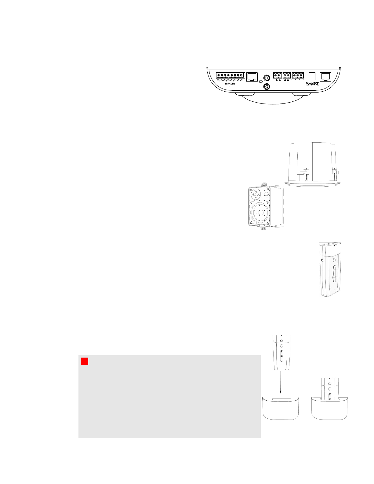
CAS-340 and CAS-360 bottom view
The underside of the control unit has a removable
panel. Under the panel are the following:
lUSB connection to the computer
lRCA connections for auxiliary inputs such
as DVD/Blu-ray players and VCRs
lConnectors for assistive listening devices
lRJ45 connection for the Cat 5e cable to the
room module
lSystem power input
lSystem reset button
Aux In Out
To R M 19 VD C
RESE T
C H A P T E R 1
Getting started
5
PAGIN G
INPU T
6-12VDC
INPU T
NINI
TO C U
RELAY
OUTPU T
N.C. N.O.COM
SMART Bus
Expansion
Sensors
Room module
The room module contains the infrared sensor
and the speaker amplifiers. The room module is
ceiling-mounted and is connected to all of the
speakers.
The room module connects to the control unit with a Cat 5e cable.
Ceiling speakers
SMART Audio system ceiling speakers receive both power and sound input
through speaker wire from the room module. Speaker strength is 30 W.
Wall speakers
SMART Audio system ceiling speakers receive both power and
sound input through speaker wire from the room module.
Speaker strength is 30 W.
Microphone
Your SMART Audio system includes a microphone that transmits an infrared signal by line
of sight up to 15' (4.6 m) to a receiver in the room module. The microphone has a built in
voice receiver and you can also add external wired microphones to the 3.5 mm jack on the
side of the microphone.
You can attach the included lanyard to the microphone and wear it around your neck. The
microphone has power, volume and mute buttons.
Microphone charging cradle
Charge the microphone in the wall-mounted microphone charging
cradle provided with your SMART Audio system.
For more information on charging your microphone, see page 13.
W W A R N I N G
lDo not charge the battery with any charger other than the one
supplied. Do not charge other battery types in your SMART
product with the supplied power adapter. These actions can
cause damage to the product and can cause a fire or personal
injury.
lIf the SMART product becomes excessively warm or emits
an unusual smell while the battery is recharging, immediately
disconnect the power cable from the power outlet.
C H A P T E R 1
Getting started
6

SMART software
Your SMART Audio system operates without additional software. However, the following software
will extend your usage of the SMART Audio system.
lSMART Notebook software and SMART Product Drivers enable you to access commonly
used audio settings, such as volume control, while teaching.
lSMART Audio software enables you to control the SMART Audio system from SMART
Notebook software.
lSMART Audio configuration software enables an installer or system administrator to
customize the SMART Audio system.
You can install SMART software from the included CD or from smarttech.com/downloads.
C H A P T E R 1
Getting started
7


Chapter 2: Using the control unit
Turning on and turning off your SMART Audio system 9
Auxiliary audio inputs for the control unit 10
Connecting auxiliary audio input devices to the control unit 10
System reset 10
The control unit has the following roles in your SMART Audio system:
lProviding power to the room module and the speakers through the Cat 5e cable to the room
module
lConnecting to your computer for audio system adjustments using the SMART Audio system
software
lProviding customization through an LCD screen and adjustment dial (CAS-360 only)
lProviding volume control (CAS-360 only)
Turning on and turning off your SMART Audio
system
Your control unit has a power button that turns on your SMART Audio system, including your room
module and ceiling speakers or wall speakers, and turns off your SMART Audio system.
Power button
gTo turn on or turn off your SMART Audio system
Press the power button on the control unit.
Chapter 2
9

I I M P O R T A N T
The microphone has its own power button. For more information, see page 15.
Auxiliary audio inputs for the control unit
You can connect auxiliary audio inputs to the control unit, such as a CD player, VCR, DVD/Blu-ray
player or other media device. You can transmit sound from these devices as an alternative to voice
input from your microphone.
When your SMARTAudio system is turned on, you can control the volume and mute features using
the auxiliary input controls, with SMART Audio software (see page 27), or the system microphone
(see page 17).
N N O T E
For more information on connecting audio inputs directly to the microphone, see page 16.
Connecting auxiliary audio input devices to the control unit
gTo connect the auxiliary audio input device to the control unit
1. Ensure that the auxiliary audio input device is turned off.
2. Remove the bottom cover from the control unit.
3. Connect two RCA input plugs to the Aux 2 inputs.
4. Replace the cover on the control unit.
System reset
If you encounter issues with your SMART Audio system, you can reset it.
gTo reset the system
1. Remove the control unit bottom cover.
2. Press the labeled system reset button for three seconds.
The system resets.
3. Replace the control unit bottom cover.
C H A P T E R 2
Using the control unit
10

Chapter 3: Using the SMART Audio system
microphone
Parts of the microphone 12
Assembling the microphone 12
Placing a battery in the microphone 13
Using the microphone's protective sleeve 13
Connecting the lanyard to the microphone 13
Charging the microphone 13
Charging time 14
Charge duration 14
Turning on and turning off the microphone 15
Connecting the microphone to the room module 15
Speaking into the microphone 15
Adjusting microphone volume 16
Adding auxiliary microphones 16
Connecting auxiliary audio input devices to the microphone 16
Controlling an auxiliary audio input device using the microphone 17
Using a second microphone 18
Using microphone channels 18
Checking your microphone mode 18
Enabling Assigned Channel mode 19
Enabling Find Channel mode 19
Customizing a microphone 20
Enabling Button Disable mode 20
Enabling Automatic On and Automatic Off mode 21
Downloading global settings from the control unit 22
The SMART Audio system microphone is a voice input device that transmits a line-of-sight infrared
signal up to 15' (4.6 m) to the room module. The room module receives the input, and then passes the
audio input to the speakers through the speaker wires according to SMARTAudio software settings.
Chapter 3
11

You can use a second microphone with the SMARTAudio system. For more information, see page
18.
The microphone is battery operated and chargeable with the included microphone charging cradle. For
more information, see page 13.
Parts of the microphone
The microphone has several controls and connections, as described below.
Assembling the microphone
The microphone has a battery, a protective sleeve and a lanyard.
C H A P T E R 3
Using the SMART Audio system microphone
12

Placing a battery in the microphone
The microphone uses a replaceable, rechargeable 3.7V lithium ion battery.
gTo place a battery in the microphone
1. Remove the back panel of the microphone.
2. Remove the plastic film from the battery.
3. Insert the battery into the microphone with the label facing out and down.
4. Replace the back panel of the microphone.
Using the microphone's protective sleeve
The microphone has a protective sleeve. Slide the microphone into the sleeve to reduce sound
transfer from tapping the microphone and to protect the microphone from damage.
Connecting the lanyard to the microphone
The microphone has a lanyard for hands-free use.
gTo connect the lanyard to the microphone
Slide the lanyard mounting plate into the back of the microphone.
Charging the microphone
You can charge the microphone in the microphone charging cradle or by connecting the charging
cable directly to the bottom of the microphone.
C H A P T E R 3
Using the SMART Audio system microphone
13

W W A R N I N G
lDo not charge the battery with any power adapter other than the one supplied.
lDo not charge other battery types in your SMART product with the supplied power adapter.
Both of these actions can cause damage to the product and can cause a fire or personal
injury.
lIf the SMART product becomes excessively warm or emits an unusual smell while the
battery is charging, immediately disconnect the power adapter from the power outlet and turn
off the product.
Charging time
It takes approximately one hour to charge the microphone.
Charge duration
A full charge provides approximately seven hours’ use. This time can vary depending on the
frequency of transmission, battery age and room temperature.
gTo charge the microphone in the microphone charging cradle
1. Connect AC power adaptor into the microphone charging cradle.
2. Place the microphone in the charger facing out.
T T I P
The microphone is more stable if it is in its protective sleeve.
For more information, see page 13.
The red light will start to flash when the microphone is charging,
and will turn solid red when the microphone is fully charged.
gTo charge the microphone directly
Connect the AC power adapter jack directly to the connection on bottom of microphone.
C H A P T E R 3
Using the SMART Audio system microphone
14
Other manuals for Audio CAS-340
2
This manual suits for next models
1
Table of contents
Other SMART Speakers manuals


Popular Speakers manuals by other brands


Logitech
Logitech Z200 Complete Setup Guide

LANTEVA
LANTEVA 601 installation instructions

Definitive Technology
Definitive Technology DI 4.5R owner's manual

Kenwood
Kenwood XXV-04S - 25th Anniversary Car Speaker... instruction manual

Peavey
Peavey SP 4P manual

Federal Signal Corporation
Federal Signal Corporation A12SA manual