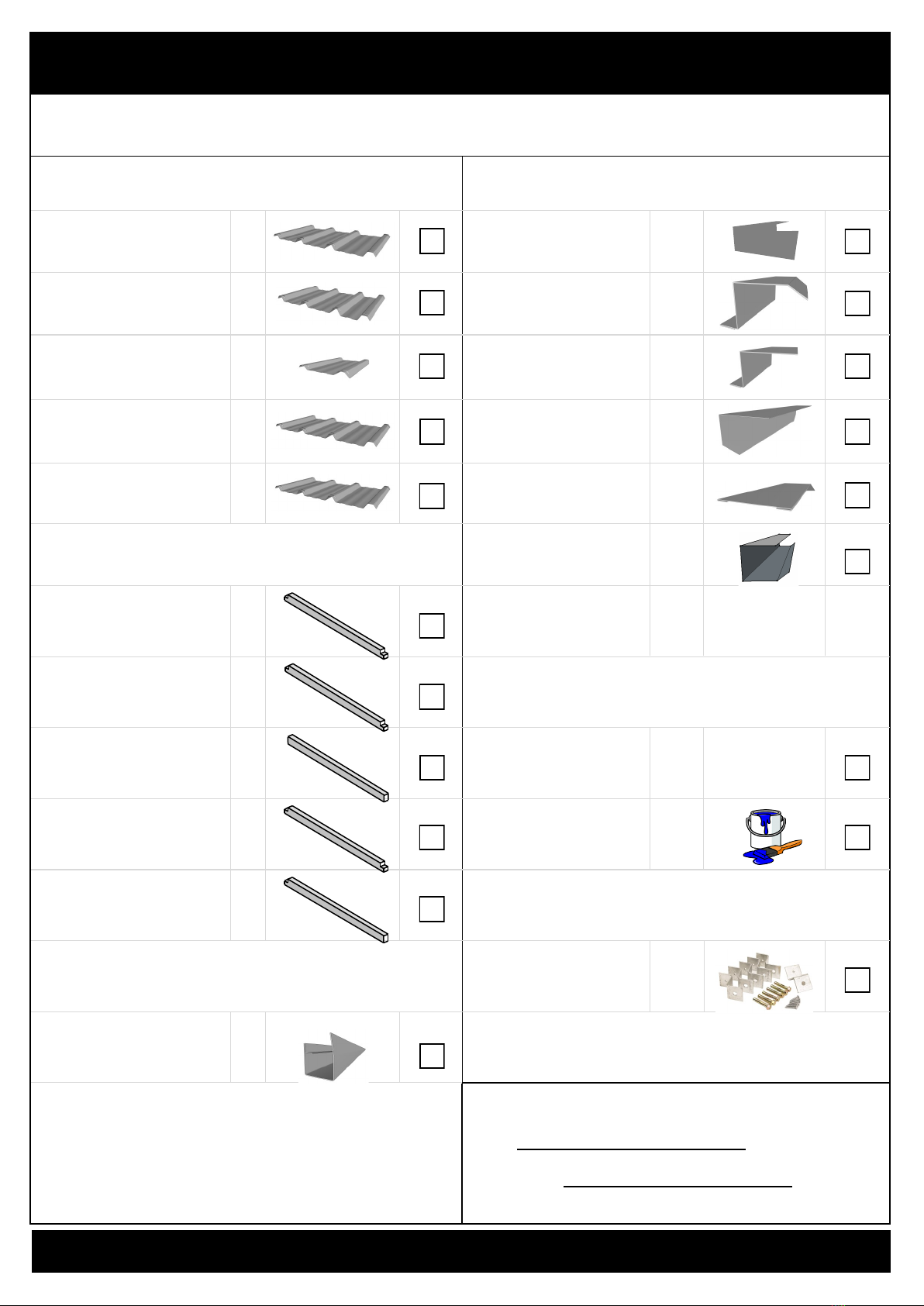
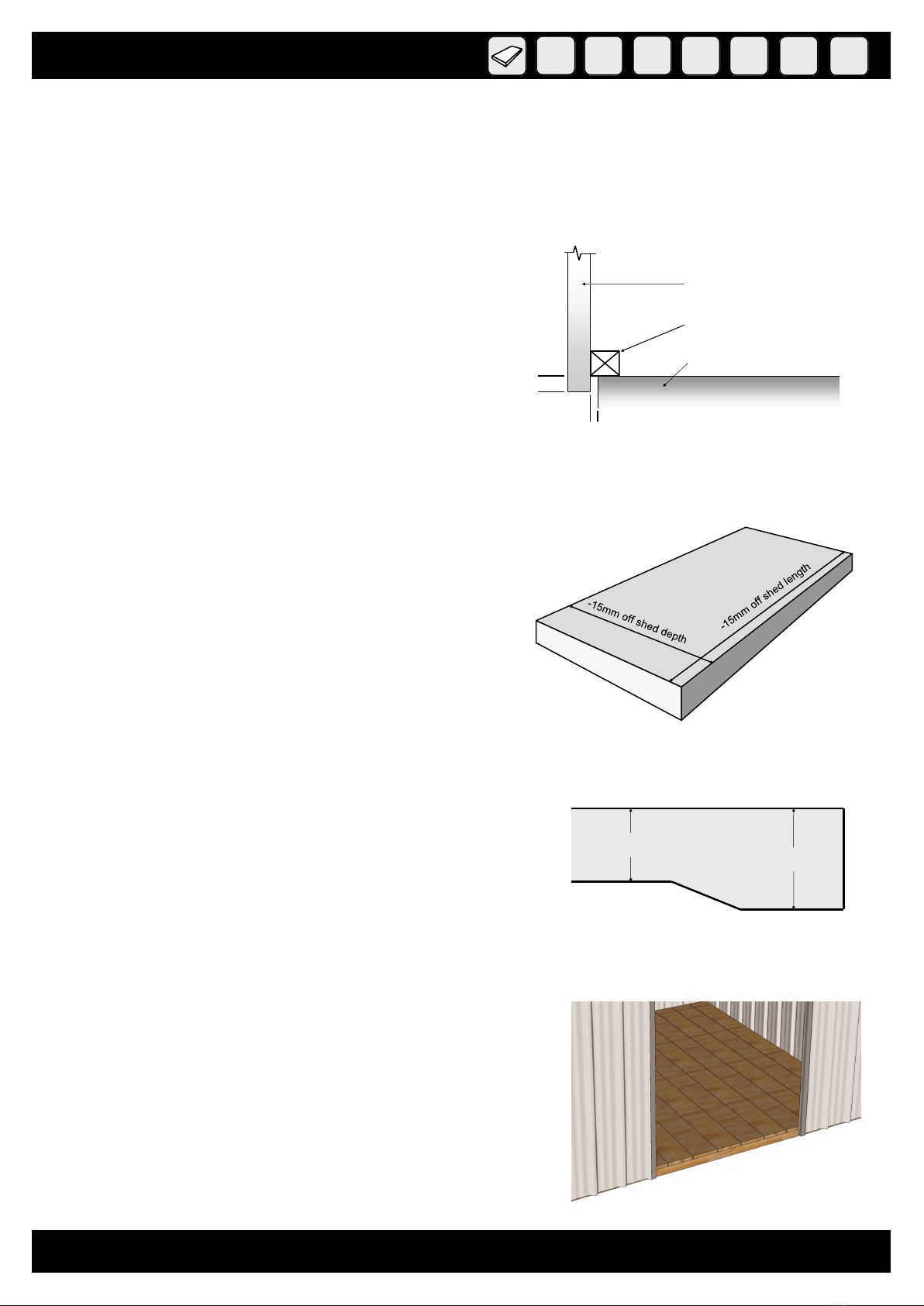
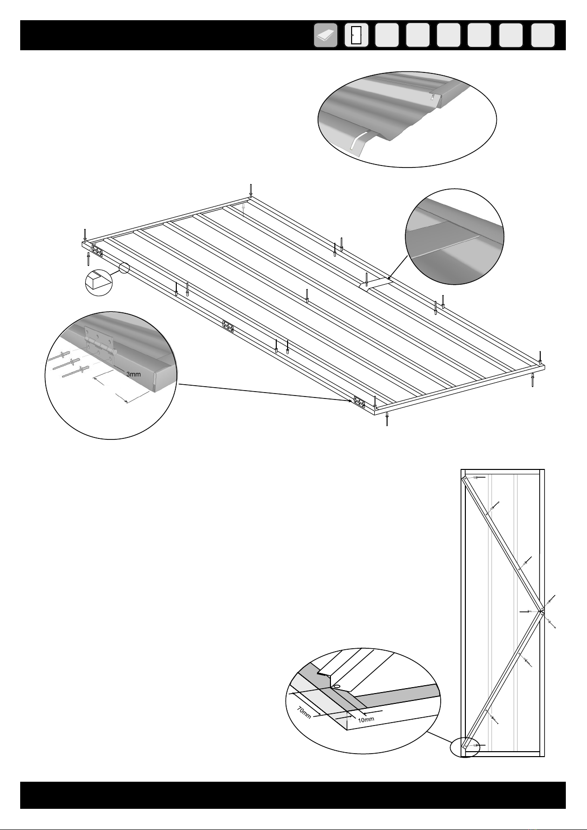
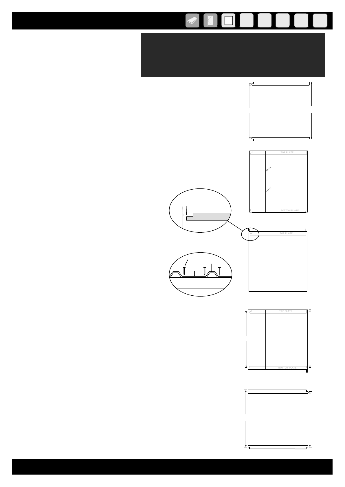
SmartStore SS1507 User manual


Other SmartStore Outdoor Storage manuals

SmartStore
SmartStore SS2015 User manual

SmartStore
SmartStore SM3015 User manual

SmartStore
SmartStore SM1515 User manual

SmartStore
SmartStore SS1515 User manual

SmartStore
SmartStore SS2020 User manual

SmartStore
SmartStore SS2525 User manual

SmartStore
SmartStore SS3025 User manual

SmartStore
SmartStore SM3025 User manual

SmartStore
SmartStore SS2515 User manual

SmartStore
SmartStore SM2525 User manual

SmartStore
SmartStore SM2520 User manual

SmartStore
SmartStore SS1510 User manual

SmartStore
SmartStore SS2520 User manual

SmartStore
SmartStore SM1520 User manual

SmartStore
SmartStore SS2010 User manual

SmartStore
SmartStore SM3020 User manual

SmartStore
SmartStore SM2020 User manual

SmartStore
SmartStore SM1020 User manual

SmartStore
SmartStore SM2515 User manual

SmartStore
SmartStore SS3030 User manual


Popular Outdoor Storage manuals by other brands

STOREHAUS
STOREHAUS EL-3048x1829-WD0-D1-PT Instructions for assembly, maintenance and safe use

Keter
Keter FACTOR 4x6 user manual

Décor et Jardin
Décor et Jardin MODULES 12 11971-000 Assembly Notice
Arrow Storage Products
Arrow Storage Products FKE02 Series Owner's manual & assembly guide

STILLA
STILLA Palmwood Assembly instructions
Arrow
Arrow HM101267-A1 Owner's manual & assembly instructions

Sentry Buildings
Sentry Buildings Roanoke II Assembly Book

Yardmaster
Yardmaster 107 TYZ manual

Lifetime
Lifetime 60354 Assembly instructions

USP
USP DURAMAX 10.5 Ft x 3 Ft SidePro owner's manual

garofalo
garofalo TUSCANY BOX 100 user manual

USP
USP DURAMAX Aluminium Skylight Shed Owner's manual/ instructions for assembly

Creative Play
Creative Play TRIKE STORE Assembly and installation instructions

Décor et Jardin
Décor et Jardin BUCHER Assembly Notice

Karibu
Karibu 75407 Building instructions

Mercia Garden Products
Mercia Garden Products 01PTSHPCHEST-V1 General instructions

Duratuf
Duratuf Garrison PL84 Assembly instructions

Tiger
Tiger TigerFlex Shiplap Pent General assembly instructions