STILLA Palmwood User manual

STILLA
ASSEMBLY INSTRUCTIONS
‘Palmwood’6x6
S3011
Every part needed to construct your shed is included inside the pack; cedar
panels, doors, windows, hardware kits & roof sheeting. Please ensure you fully
unpack all the parts & check against the parts checklist before contacting
customer service about anything you believe may be missing. Thank-you!
1 | P a g e
Caution
Please be careful when handling all components, some parts have sharp metal edges.
Always wear work gloves, eye protection and long sleeves when assembling or maintaining
your shed.
Tools required for assembly
•Level
•Drill
•Hammer
•Ladder
•12mm Drill bit
•6mm Drill bit
•Phillips head drive
•Hex Head Drive (5/16’)
•Safety glasses
•Gloves
Before assembly
•Remove all parts from packages and place in a safe place close to assembly area.
•Review all instructions; continue to refer to instructions throughout assembly –step
by step.
Preparing your site
•Choose your site carefully, site surface must be level (unless an Elevation kit or
Heavy duty floor kit option has been purchased with your product)
PALMWOOD 6x6 PARTS CHECKLIST
Part Code
Checked
Part Description
Qty
P
Cedar Clad Panel 900x1890mm
6
FP
Cedar Clad Panel 480x1890mm (180x1890 if Double Doors)
2
FG
6 Foot Front Gable
1
BG
6 Foot Back Gable
1
R
Rafters 900x42x35mm
6
CD
Single Colonial Door 830x1875mm
1
C
2115mm Chanel
2
TB/BB
Top Batten/Bottom Batten 2115mm
4
RS
1150mm Roof Sheeting
6
N/A
6x6 Hardware Kit
1
RC
1200mm Ridge Cap
2
F
6ft Fascia Pack
1
CP
1890x61x18mm Corner Posts
4
CS
1890x40x7mm Cover Strips
3
DH
840mm Door Head (1440x42x35mm if Double Doors)
1
DS
840mm Door Step (1440x42x19mm if Double Doors)
1
CT
Collar Tie 480mm
1
IM
6x6 Instruction Manual
1
2 | P a g e
Floor Kit –Option
Floor Frame - (Rebated Floor 70x35mm/Heavy Duty Floor 140x35mm)
Part Code
Checked
Part Description
Qty
EP
End Plate 1870mm
2
DJ
Double Joist 1730mm
2
SJ
Single Joist 1730mm
3
L
Logs (light duty floor does not come with logs)
4
FB
1798mm x 800
2
FB
1798mm x 111
1
6 Foot Loft Shelf - Option
Part Code
Checked
Part Description
Qty
6LS
6ft Loft Shelf
1
Double Doors –Option –Changes to above kit
Part Code
Checked
Part Description
Qty
CD
Colonial Door 714x1875mm
2
FP
Front Panel 180x1890mm
2
DP
Door Leaver Packer 100x100x18mm
1
DS
Door Stop 1440x42x19
1
DH
Door Head 1440x42x35
1
6x6 Lean To –Option –Add Extra Screws
Part Code
Checked
Part Description
Qty
B
Beam 2115x70x35mm
1
VB
Verandah Beam 2115x140x35mm
1
VR
Verandah Rafter 1000x42x35mm
3
VP
Verandah Posts 2400x90x90mm
2
VF
Verandah Fascias 1100x75x20mm
2
VS
Verandah Roof Sheets 1150mm
3
6x6 Annex –Option –Add Extra Screws
Part Code
Checked
Part Description
Qty
B
Beam 2115x70x35mm
1
VB
Verandah Beam 2115x140x35mm
1
VR
Verandah Rafter 1930x42x35mm
3
VP
Verandah Posts 2400x90x90mm
2
VF
Verandah Fascias 2000x75x20mm
2
VS
Verandah Roof Sheets 2050mm
3
3 | P a g e
If no floor option was purchased, go to step 2.0 (Wall Assembly)
STEP 1.0
FLOOR KIT
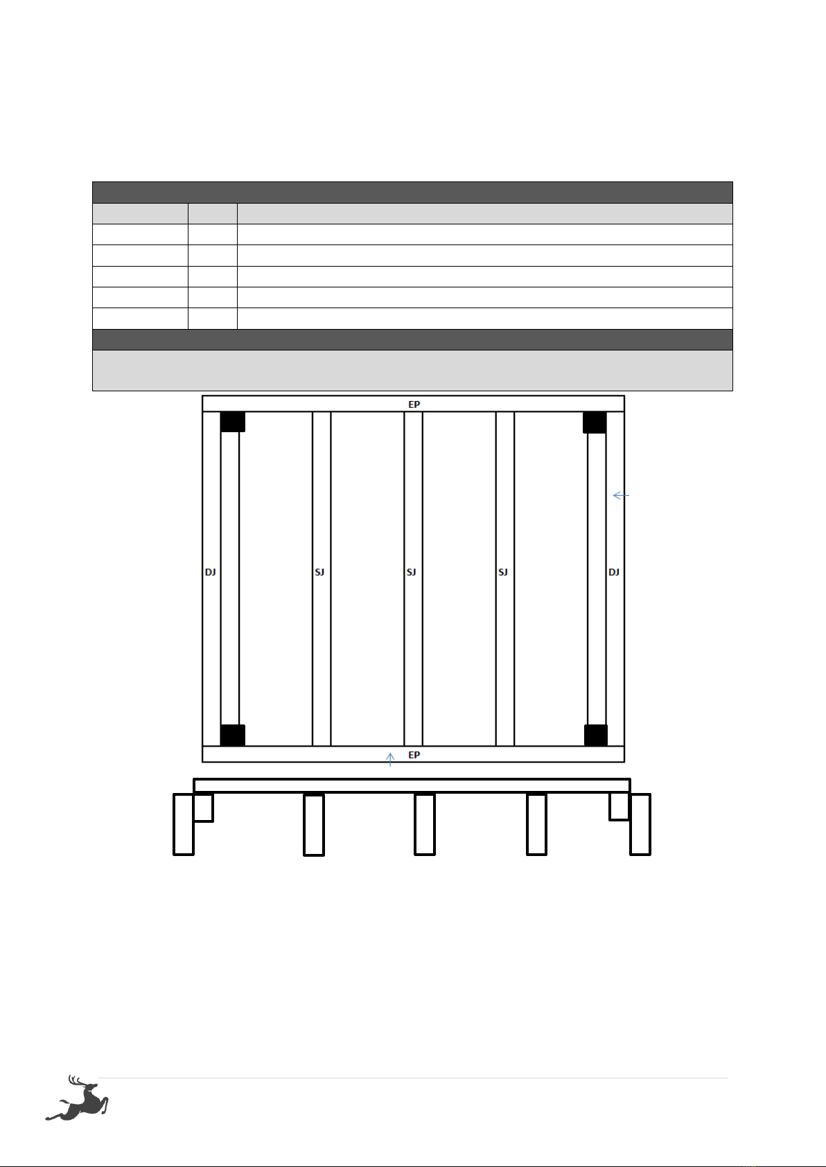
1.0 –FLOOR KIT
PART CODE
QTY
DESCRIPTION
EP
2
End Plate 1870mm
SJ
3
Single Joist 1730mm
DJ
2
Double Joist 1730mm (42x35mm part of DJ goes at the top inside)
100BS
24
100mm Batten screw (Heavy Duty Floor Only)
75N
24
75mm Nail (Rebated Floor Only)
1.0 –FLOOR FRAME
Screw through EP into DJ using 3 x 100BS per join (75N on Rebated Floor)
Screw Through EP into SJ using 2 x 100BS per join (75N on Rebated Floor)
HEAVY DUTY FLOOR KIT
Heavy duty floor can be installed on unlevelled ground –use supplied logs to level your floor
by digging them into the ground.
Install heavy duty floor kit using (L) 4 logs –1 in each corner (position shown above) screw
through frame into log using 4 x 100BS per corner
Ensure floor frame is square by measuring from corner to corner diagonally prior to
installing flooring.
Yellow Tongue
DJ
DJ
SJ
SJ
SJ
4 | P a g e
STEP 1.1
FLOORING INSTALLATION
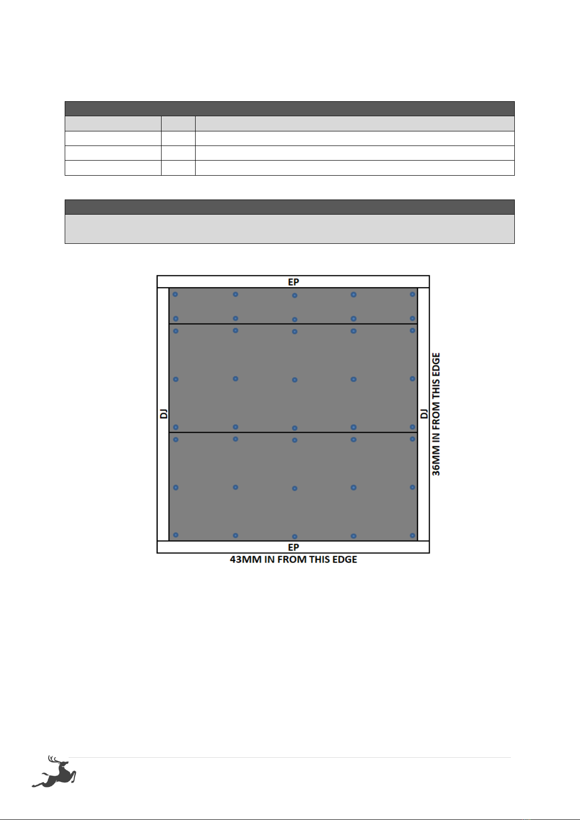
1.1 –FLOOR INSTALLATION
PART CODE
QTY
DESCRIPTION
FB
2
Floor Board 1798x800mm
FB
1
Floor Board 1798x111mm
50PS
40
50mm Philips Screw
1.1 –FLOOR SHEETS
Fasten floor sheets to floor frame as shown below using 50PS –Note, the Palmwood now
has 3 sheets, the above is correct.
This manual suits for next models
1
Table of contents
Other STILLA Outdoor Storage manuals


Popular Outdoor Storage manuals by other brands

LIVING AND HOME
LIVING AND HOME 0735940285711 user guide

USP
USP DURAMAX 10 Ft x 8 Ft StoreMax Plus owner's manual

rollaway container
rollaway container ARPCA24 manual

Duratuf
Duratuf GL105 Assembly instructions

Viking
Viking SD5300SS Use & installation guide

USP
USP DURAMAX Apex Pro 10.5 Ft x 8 Ft 40116 owner's manual


