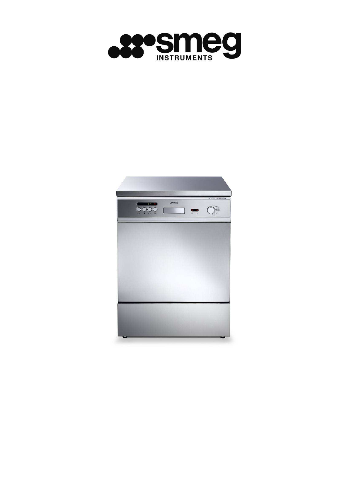
WD1050 12/04/2010 Pag. 1
TABLE OF CONTENTS
1. INTRODUCTION................................................................................................3
2. SYMBOLS LEGEND ..........................................................................................4
3. GENERAL RECOMMENDATIONS.....................................................................4
4. GENERAL SPECIFICATIONS............................................................................6
4.1. TECHNICAL FEATURES.............................................................................................6
4.2.
LIFTING
AND
HANDLING............................................................................................7
4.3.
DOOR
LOCKING
SYSTEM..........................................................................................7
4.4.
MANUAL
DOOR
UNLOCKING.....................................................................................8
5. INSTALLATION .................................................................................................9
5.1.
POSITIONING.............................................................................................................9
5.2.
LEVELLING.................................................................................................................9
5.3.
CONNECTION
TO
WATER
MAINS ..............................................................................9
5.4.
WATER
SUPPLY.......................................................................................................11
5.5.
NON
PRESSURIZED
DEMINERALIZED
WATER
CONNECTION................................12
5.6.
WATER
DRAIN
CONNECTION..................................................................................13
5.7.
ELECTRICAL
CONNECTION.....................................................................................14
6. DESCRIPTION OF CONTROLS....................................................................... 15
6.1.
WASHING
PROGRAMME
SETTINGS........................................................................16
6.2.
THERMAL
DISINFECTION
IN
ACCORDANCE
WITH
THE
PARAMETER
"A0".............16
6.3.
PROGRAMMES
DESCRIPTION ................................................................................18
6.4.
MACHINE
RUNNING.................................................................................................19
6.5.
RESIN
WASHING
PHASE .........................................................................................20
6.6.
RESIN
REGENERATION
PHASE...............................................................................20
6.7.
PROGRAMME
TERMINATION ..................................................................................20
6.8.
IN
PROGRESS
PROGRAMME
INTERRUPTION........................................................20
6.9.
RESET
PROCEDURE ...............................................................................................20
6.10.
DATE
AND
TIME
SETUP.........................................................................................21
6.11.
DEMI
WATER
SETTING..........................................................................................21
6.12.
PRINTER ................................................................................................................22
6.13.
PRINTER
LANGUAGE.............................................................................................23
7. OPERATING INSTRUCTIONS ......................................................................... 23
7.1.
USE
OF
THE
WATER
SOFTENER.............................................................................24
7.2.
USE
OF
THE
DETERGENT
AND
NEUTRALIZING
AGENT.........................................24
7.3.
DETERGENT
AND
NEUTRALIZING
AGENT
RECOMMENDED
BY
SMEG..................25
8. ALARMS..........................................................................................................27
9. CLEANING AND MAINTENANCE....................................................................31
9.1.
RECOMMENDATIONS
AND
GENERAL
ADVICE........................................................31
9.2.
IF
THE
INSTRUMENT
WASHER
IS
NOT
USED
FOR
A
LONG
PERIOD
OF
TIME........33