SMH Technologies FlashRunner FR01AT0 User manual


FlashRunner
FR01AT0
High-Performance,
Standalone In-System
Programmer
User’s Manual
Revision 1.3— April 2015
Copyright © 2015 SMH Technologies
DC10730

We want your feedback!
SMH Technologies is always on the lookout for new ways to improve its
Products and Services. For this reason feedback, comments,
suggestions or criticisms, however small, are always welcome.
Our policy at SMH Technologies is to comply with all applicable worldwide safety and EMC/EMI
regulations. Our products are certified to comply with the European New Approach Directives and the
CE mark is applied on all our products.
This product as shipped from the factory has been verified to meet with requirements FCC as a CLASS
A product.
In a domestic environment, this product may cause radio interference in which case the user may be
required to take adequate prevention measures.
Attaching additional wiring to this product or modifying the product operation from the factory default as
shipped may effect its performance and cause interference with other apparatus in the immediate
vicinity. If such interference is detected, suitable mitigating measures should be taken.
SMH Technologies
E-mail (general information): info@smh-tech.com
Web: http://www.smh-tech.com
Important
SMH Technologies reserves the right to make improvements to FlashRunner, its documentation and software routines, without
notice. Information in this manual is intended to be accurate and reliable. However, SMH Technologies assumes no
responsibility for its use; nor for any infringements of rights of third parties which may result from its use.
SMH TECHNOLOGIES WILL NOT BE LIABLE FOR DAMAGES RESULTING FROM LOSS OF DATA, PROFITS, USE OF
PRODUCTS, OR INCIDENTAL OR CONSEQUENTIAL DAMAGES, EVEN IF ADVISED OF THE POSSIBILITY THEREOF.
Trademarks
SMH Technologies is the licensee of the SofTec Microsystems trademark.
All other product or service names are the property of their respective owners.
Written by Paolo Xausa
Our policy at SMH Technologies is to comply with all applicable worldwide safety and
EMC/EMI regulations.
This product is certied to comply with the 2004/108/EC Directives and is in conformity
with the EN6100-6-2 and the EN61000-6-3 standards.
In a domestic environment, this product may cause radio interference in which case the
user may be required to take adequate prevention measures.
Attaching additional wiring to this product or modifying the product operation from the
factory default as shipped may effect its performance and cause interference with other
apparatus in the immediate vicinity. If such interference is detected, suitable mitigating
measures should be taken.
Disposal of Waste Electrical & Electronic Equipment (WEEE).
In the European Union, this label indicates that this product should not be disposed of
with household waste. It must be deposited in an appropriate facility to allow for recovery
and recycling. For more detailed information about the recycling of this product, please
contact your local city ofce, household waste disposal service or the retail store where
you purchased this product.

FlashRunner FR01AT0 User's Manual
Contents
0Before Starting 9
0.1 Important Notice to Users 9
0.2 Safety 9
0.3 Getting Technical Support 10
0.4 Additional Documentation 10
1Overview 11
1.1 What is FlashRunner FR01AT0? 11
1.1.1 General features 12
1.1.2 Hardware features 13
1.1.3 Advanced Hardware Features 13
1.1.4 Software features 14
1.2 Package Checklist 14
1.3 Hardware Overview 15
1.3.1 Power Supply 16
1.3.2 LAN Connector 16
1.3.3 RS-232 Connector 16
1.3.4 Control Connector 16
1.3.5 ISP Connector 16
1.3.6 Start Push-Button 16
1.3.7 Optoisolation 17
1.4 Programming Algorithms and Licenses 17
1.4.1 Installing New Licenses 17
1.5 Upgrading the Firmware 18
2System Setup 19
2.1 Overview 19
2.2 Software Setup 19
2.3 Hardware Setup 20

Contents
2.3.1 Interfacing FlashRunner with your Test/Programming
Equipment 20
2.3.2 Connecting FlashRunner to the Host PC System 21
2.3.3 Powering Up FlashRunner 21
2.3.4 Setting Up LAN Settings 21
2.4 Step-by-Step Tutorial: Sending Commands to FlashRunner 21
3Connectors 29
3.1 Overview 29
3.2 ISP & I/O Connector 29
3.3 Control Connector 33
3.4 RS-232 Connector 34
4Technical Specifications 37
4.1 Absolute Maximum Ratings 37
4.2 DC Characteristics and Functional Operating Range 37
4.3 AC Characteristics (“ISP” Mode) 40
4.4 Relay Characteristics 41
4.5 Physical and Environmental Specifications 42

FlashRunner FR01AT0 User's Manual
Index of Figures
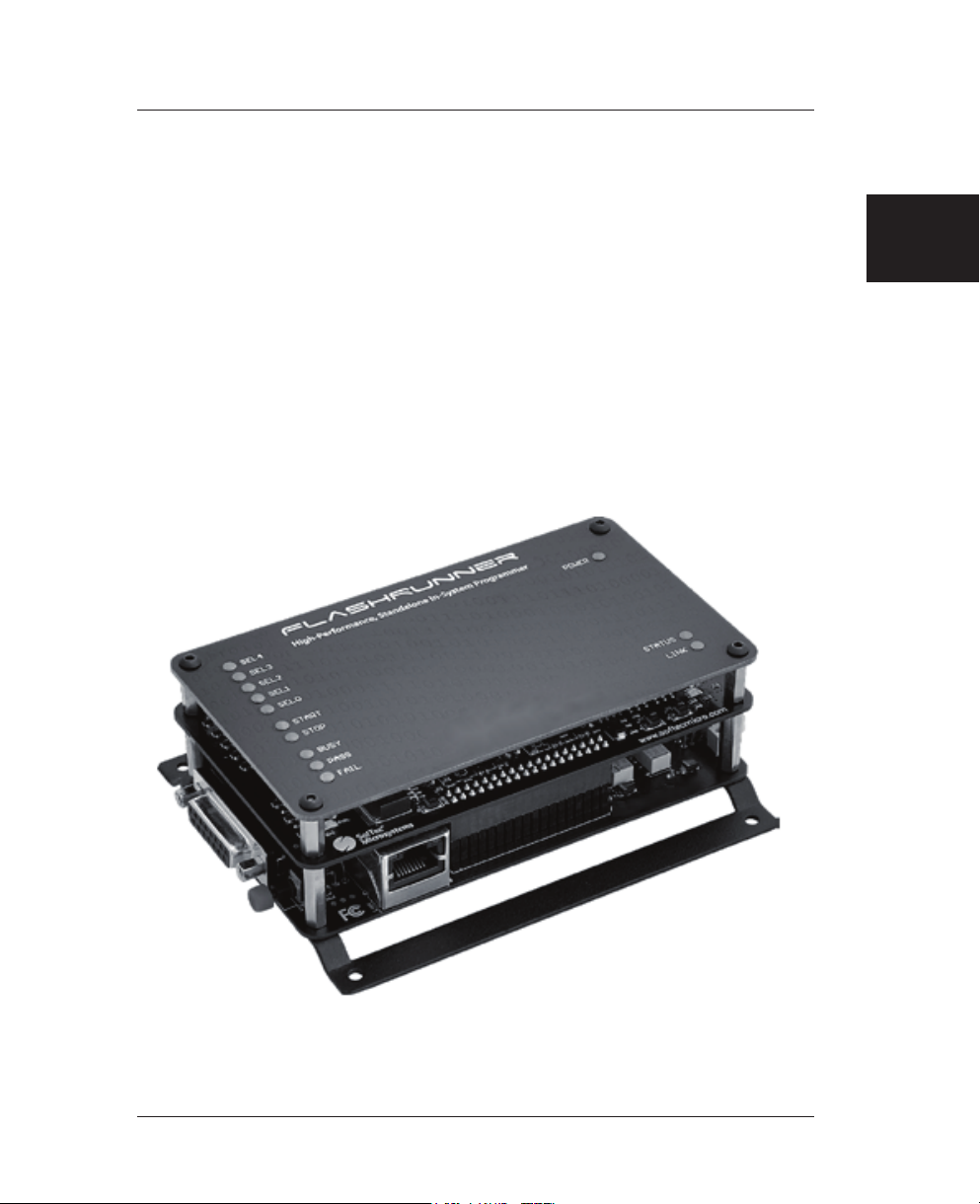
Figure 1.1: FlashRunner FR01AT0 11
Figure 1.2: FlashRunner FR01AT0 I/O Lines Routing 12
Figure 1.3: FlashRunner FR01AT0 Connectors 15
Figure 2.1: FlashRunner Control Panel, Communication Settings 23
Figure 2.2: FlashRunner Control Panel, Target Device Configured 24
Figure 2.3: FlashRunner Control Panel, Binary File Conversion 25
Figure 2.4: FlashRunner Control Panel, File Transfer 26
Figure 2.5: FlashRunner Control Panel, Target Device Programmed 27
Figure 3.1: ISP & I/O Connector 30
Figure 3.2: Relay Wiring 31
Figure 3.3: Shielded ISP Line 32
Figure 3.4: Control Connector 33
Figure 3.5: RS-232 Connector 35
Figure 4.1: Load Conditions 41
Figure 4.2: Connection Layer Layout and Dimensions 42


FlashRunner FR01AT0 User's Manual
Index of Tables
Table 3.1: ISP & I/O Connector Signals 30
Table 3.2: ISP and ATE I/O Signal Association 32
Table 3.3: Control Connector Signals 34
Table 3.4: RS-232 Connector Signals 35
Table 4.1: Absolute Maximum Ratings 37
Table 4.2: DC Characteristics and Functional Operating Range 38
Table 4.3: AC Characteristics (“ISP” Mode) 40
Table 4.4: Relay Characteristics 41
Table 4.5: Physical and Environmental Specifications 42


0
FlashRunner FR01AT0 User's Manual
0 Before Starting
i
Note: the FlashRunner System Software CD-ROM and/or
SofTec Microsystems website (www.softecmicro.com) may
contain an updated version of this user’s manual. Please
check before continuing reading this documentation.
0.1 Important Notice to Users
While every effort has been made to ensure the accuracy of all information in
this document, SMH Technologies assumes no liability to any party for any
loss or damage caused by errors or omissions or by statements of any kind
in this document, its updates, supplements, or special editions, whether such
errors are omissions or statements resulting from negligence, accidents, or
any other cause.
0.2 Safety
FlashRunner is a low-voltage device. However, when integrating it inside an
automatic test equipment or when interfacing it with other systems, take all
precautions in order to avoid electrical shocks due to, for example, different
ground references.
Make all connections to the target system before applying power to the
instrument.
To protect FlashRunner against electrostatic discharge (ESD), always
connect yourself to ground (e.g. via wrist straps) when handling the
instrument.
Always store FlashRunner inside an antistatic bag when not in use.
9
Note: the FlashRunner System Software CD-ROM and/or
SMH Technologies website (www.smh-tech.com) may con-
tain an updated version of this user’s manual. Please check
before continuing reading this documentation.

Before Starting
00.3 Getting Technical Support
SMH Technologies is continuously working to improve FlashRunner
firmware and to release programming algorithms for new devices. SMH
Technologies offers a fast and knowledgeable technical support to all of its
customers and is always available to solve specific problems or meet
specific needs.
To get in touch with SMH Technologies, please refer to the contact
information below.
Phone: +39 0434 421111
Fax: +39 0434 639021
Technical Support: support@smh-tech.com
0.4 Additional Documentation
This user’s manual provides information about how to setup FlashRunner
FR01AT0 and its hardware characteristics.
For information about FlashRunner commands and their syntax, including
specific commands for specific family of microcontrollers, please refer to the
FlashRunner Programmer’s Manual, included (in PDF format) in the
FlashRunner CD-ROM.
10
1
FlashRunner FR01AT0 User's Manual
1 Overview
1.1 What is FlashRunner FR01AT0?
FlashRunner FR01AT0 is a member of the FlashRunner series of a high-
performance, standalone In-System Programmers specific for Flash-based
microcontrollers and serial memories.
FlashRunner FR01AT0 is targeted at production environments and can work
either in full standalone mode or controlled by a host system.
FlashRunner FR01AT0 is specifically designed for an easy integration with
all in-circuit and functional test systems (ATEs), like Agilent, Teradyne,
SPEA, TRI and others.
Figure 1.1: FlashRunner FR01AT0
11

1
Overview
A relay circuitry allows each of the FlashRunner ISP lines to be
independently disconnected from the target system, routing I/O lines coming
from the ATE system to the target system instead. The figure below
illustrates the concept.
2 FORM-C RELAY
(DPDT) PER LINE
ISP GND
ISP LINE
FlashRunner
ENGINE
NC
NC
FR01AT0
NAIL
12 x I/O LINE +
SHIELD
12 I/O LINES
FROM ATE
FIXTURE
ISP & I/O CONNECTOR (48 WAYS)
x 12
I/O or ISP LINE
SHIELD
Target System
Figure 1.2: FlashRunner FR01AT0 I/O Lines Routing
1.1.1 General features
Fastest programming algorithms (as fast as target device’s memory
technology limit), approved by silicon manufacturers;
Easy ATE integration;
Standalone operations (projects and code images stored on a memory
card);
Controllable by ATE through optoisolated LAN, RS-232 or parallel
control lines;
Supports most ISP protocols (BDM, JTAG, SPI, I2C, MON, ICC, SCI,
etc.);
12

1
FlashRunner FR01AT0 User's Manual
Flexible, fully configurable;
Compact and robust design for production environments;
Data integrity guaranteed (every data transfer to/from the host system
or Secure Digital card is CRC tagged).
1.1.2 Hardware features
9 to 24V power supply input;
Galvanic isolation (relay disconnection) with shield to fixture for all I/O
ISP lines:
Five digital I/O lines;
Two digital I/O or analog output lines;
Two programmable output voltages (0 to 15V, 0.25A and 0 to 5V,
0.5A)
One analog input line
One programmable clock output
Secure Digital memory card (up to 2 GB);
512 bytes on-board dynamic memory;
On-board timekeeper and calendar for time-stamped log file;
Three optoisolated command inputs (START, STOP, RELAY);
Three optoisolated status outputs (FAIL, PASS, BUSY);
Five project selection lines (SEL[4..0]);
Optoisolated RS-232/Ethernet channels.
1.1.3 Advanced Hardware Features
Galvanic isolation (relay disconnection) for all I/O ISP lines (to put
shared ISP lines on HiZ when the ATE is performing tasks other than
programming);
Power voltage monitoring (on three ISP lines), with programmable
threshold and pulse width, to continuously check if an ISP power supply
line voltage falls below a safe level;
Over current monitoring on programmable power supply lines;
13

1
Overview
Multiplexing on ISP lines coming from ATE or FlashRunner to the
fixture.
1.1.4 Software features
Fully autonomous standalone mode thanks to its SD memory card
(FAT16);
Controllable by any host system through a terminal utility and simple
ASCII protocol;
Up to 32 hardware-selectable projects (scripts), unlimited software-
selectable projects;
Interface Library DLL to control the instrument from within user written
applications;
Optional Data Protection System to make the contents of the binary file
to be programmed to the target device not readable (and not duplicable)
by non-authorized people;
Log files;
Erase, blank check, program, read, verify, oscillator trimming, etc.
1.2 Package Checklist
The FlashRunner FR01AT0 package includes the following items:
FlashRunner FR01AT0 unit, including an SD card already pre-installed
with the programming algorithm(s) you specified at the time of
purchase;
An Ethernet cross cable;
A RS-232 cable;
FlashRunner “System Software” CD-ROM, containing the FlashRunner
Control Panel utility and the FlashRunner Programmer’s Manual in PDF
format;
This user’s manual;
A registration card.
14

1
FlashRunner FR01AT0 User's Manual
1.3 Hardware Overview
FlashRunner FR01AT0 is composed of three layers. From bottom to top:
Connection Layer. Provides connectors to interface to your
programming/testing system. Includes a LAN and RS-232 connectors to
interface to a host system.
Programming Engine Layer. Contains the FlashRunner programming
engine, the core of the instrument.
Cover Layer. The cover layer has the function of protecting the
underlying layers and replicating the programming engine’s status
LEDs. If space is an issue when integrating FlashRunner in your
programming/testing system, the cover layer can be easily removed.
The figure below illustrates the location of the various connectors.
LAN Connector
RS-232 Connector Power Connector
“Start”
Push-Button
Control
Connector
ISP
Connector
Figure 1.3: FlashRunner FR01AT0 Connectors
15

1
Overview
1.3.1 Power Supply
FlashRunner FR01AT0 is powered through a 9-24V DC terminal block
connector.
1.3.2 LAN Connector
The LAN connector is used for communication with the host PC system. Use
the provided Ethernet cross cable to connect FlashRunner with your PC.
1.3.3 RS-232 Connector
Alternatively, communication with the host PC can be done with the RS-232
connector. Use the provided serial cable to connect FlashRunner with your
PC.
1.3.4 Control Connector
The “CONTROL” D-Sub connector groups the parallel control lines that an
ATE system can use to control FlashRunner, instead of communicating with
the instrument through the serial or Ethernet port.
1.3.5 ISP Connector
The “ISP & I/O ATE” DIN 41612 connector groups the input lines from the
ATE system and the ISP output lines from FlashRunner. FlashRunner routes
either its own ISP lines or the ATE system input lines to the target system
through dedicated relais.
1.3.6 Start Push-Button
The “START” push-button is directly connected to the FlashRunner START
line in the “CONTROL” D-Sub connector.
16

1
FlashRunner FR01AT0 User's Manual
1.3.7 Optoisolation
All signals in the “CONTROL”, “ISP & I/O ATE” and “RS-232” connectors are
optoisolated.
i
Note: for the pinout of the various connectors, see
“Connectors” on page 29.
1.4 Programming Algorithms and Licenses
FlashRunner FR01AT0 includes programming algorithms for several
devices. In order to program a specific device, however, a specific license
file for that device must be purchased.
i
Note: FlashRunner FR01AT0 comes already preinstalled
with the license(s) you specified at the moment of purchase.
You can purchase additional licenses at any future moment.
Programming algorithms and license files are stored in the SD card (see the
FlashRunner Programmer’s Manual for more information).
1.4.1 Installing New Licenses
When you buy an additional license for a specific device, you will get:
An algorithm file (.alg);
A license file (.lic);
A device-specific script example (.frs).
The .alg file contains the actual programming algorithm for the requested
device (and several other devices of the same family).
17

1
Overview
The .lic file contains an unlocking code that will let you use the programming
algorithm. A license file enables the use of a specific programming algorithm
on a specific FlashRunner instrument (licenses are serial number specific).
The script file contains an example of script to use as a starting point for your
specific programming needs (for more information on scripts, see the
FlashRunner Programmer’s Manual).
To install the new license, do the following:
1. Copy the .alg file into the \ALGOS directory of the SD card (if an
.alg file with the same name already exists, overwrite it);
2. Copy the .lic file into the \LICENSES directory of the SD card.
To copy files on the SD card, use either a standard card reader connected to
a PC or transfer the files using the FlashRunner FSSENDFILE command
(for more information on FlashRunner commands, see the FlashRunner
Programmer’s Manual).
Alternatively, you can use the FlashRunner Control Panel utility to install new
programming algorithms and licenses. For more information on the
FlashRunner Control Panel please refer to the FlashRunner Programmer’s
Manual.
1.5 Upgrading the Firmware
The FlashRunner firmware can be easily upgraded using the provided
Control Panel utility. For more information, please refer to the FlashRunner
Programmer’s Manual.
18
Table of contents
Other SMH Technologies Motherboard manuals

SMH Technologies
SMH Technologies FlashRunner LAN 2.0 User manual

SMH Technologies
SMH Technologies FlashRunner FR01ENG User manual

SMH Technologies
SMH Technologies FlashRunner Cube Series User manual

SMH Technologies
SMH Technologies FlashRunner Quattro Series User manual

SMH Technologies
SMH Technologies Flashrunner FR3070A User manual

SMH Technologies
SMH Technologies FlashRunner FR03 User manual

SMH Technologies
SMH Technologies Flashrunner FR01LAN User manual


Programming Guide")


