SMH Technologies FlashRunner LAN 2.0 User manual

FlashRunner LAN 2.0
Next Generation
High-Performance, Compact
Standalone In-System
Programmer
User’s Manual
Revision 0.5 —Apr 2021
Copyright © 2018 SMH Technologies
DC11261
2
We want your feedback!
SMH Technologies is always on the lookout for new ways to improve its Products and
Services. For this reason feedback, comments, suggestions or criticisms, however
small, are always welcome.
Our policy at SMH Technologies is to comply with all applicable worldwide safety and EMC/EMI
regulations. Our products are certified to comply with the European New Approach Directives and the
CE mark is applied on all our products.
This product as shipped from the factory has been verified to meet with requirements FCC as a CLASS
A product.
In a domestic environment, this product may cause radio interference in which case the user may be
required to take adequate prevention measures.
Attaching additional wiring to this product or modifying the product operation from the factory default as
shipped may effect its performance and cause interference with other apparatus in the immediate
vicinity. If such interference is detected, suitable mitigating measures should be taken.
SMH Technologies
E-mail (general information): info@smh-tech.com
Web: http://www.smh-tech.com
Important
SMH Technologies reserves the right to make improvements to FlashRunner, its documentation and software routines, without notice.
Information in this manual is intended to be accurate and reliable. However, SMH Technologies assumes no responsibility for its use; nor for
any infringements of rights of third parties which may result from its use.
SMH TECHNOLOGIES WILL NOT BE LIABLE FOR DAMAGES RESULTING FROM LOSS OF DATA, PROFITS, USE OF PRODUCTS, OR
INCIDENTAL OR CONSEQUENTIAL DAMAGES, EVEN IF ADVISED OF THE POSSIBILITY THEREOF.
Trademarks
SMH Technologies, SMH Technologies Logo are trademarks of SMH Technologies.
All other product or service names are the property of their respective owners.

3
Contents
1BEFORE STARTING .........................................................................................................5
1.1 IMPORTANT NOTICE TO USERS ............................................................................................5
1.2 SAFETY ...........................................................................................................................5
1.3 GETTING TECHNICAL SUPPORT ............................................................................................7
1.4 ADDITIONAL DOCUMENTATION ...........................................................................................7
2OVERVIEW .....................................................................................................................8
2.1 WHAT IS FLASHRUNNER LAN 2.0 NEXT GENERATION? ...........................................................8
2.1.1 General features ................................................................................................10
2.1.2 Hardware features .............................................................................................10
2.1.3 Software features...............................................................................................10
2.2 PACKAGE CHECKLIST........................................................................................................11
2.3 HARDWARE OVERVIEW....................................................................................................13
2.3.1 Power Supply......................................................................................................13
2.3.2 ATE Control Connector .......................................................................................13
2.3.3 LAN Connector ...................................................................................................14
2.3.4 USB Connector ...................................................................................................14
2.3.5 ISP Connectors ...................................................................................................14
2.3.6 LEDs....................................................................................................................15
2.4 PROGRAMMING DRIVERS AND LICENSES..............................................................................16
2.4.1 Installing New Licenses ......................................................................................16
2.5 CHANNEL UPGRADE LICENSES ...........................................................................................17
2.6 UPGRADING THE FIRMWARE .............................................................................................17
3SYSTEM SETUP .............................................................................................................18
3.1 OVERVIEW.....................................................................................................................18
3.2 SOFTWARE SETUP...........................................................................................................18
3.3 HARDWARE SETUP..........................................................................................................18
3.3.1 Interfacing with your Test/Programming equipment ........................................19
3.3.2 Connecting to the Host PC System .....................................................................19
3.3.3 Powering Up.......................................................................................................19
3.3.4 Setting Up LAN Settings .....................................................................................19
4CONNECTORS...............................................................................................................20

4
4.1 OVERVIEW.....................................................................................................................20
4.2 ISP CONNECTORS ...........................................................................................................20
4.3 ATE CONTROL CONNECTOR..............................................................................................25
4.4 USB CONNECTOR ...........................................................................................................26
5FLASHRUNNER LAN 2.0 NEXT GENERATION TOOLS......................................................27
5.1 RELAY BARRIER...............................................................................................................27
5.2 CABLE INTERFACE ...........................................................................................................32
6TECHNICAL SPECIFICATIONS.........................................................................................36
6.1 ABSOLUTE MAXIMUM RATINGS.........................................................................................36
6.2 DC CHARACTERISTICS AND FUNCTIONAL OPERATING RANGE ..................................................37
6.3 CCHARACTERISTICS (TBW)..............................................................................................38
6.4 PHYSICAL AND ENVIRONMENTAL SPECIFICATIONS..................................................................39
Index of Figures
Figure 1: FlashRunner LAN 2.0 Next Generation in closed case version......................9
Figure 2: Power jack, ATE control connector, USB and LAN...................................... 13
Figure 3: “ISP” DIN connectors group ......................................................................... 14
Figure 4: FlashRunner LAN 2.0 Next Generation Top Panel...................................... 15
Figure 5: DIN41612 mating pin assignment example ................................................. 21
Figure 6: ISP Connector.............................................................................................. 22
Figure 7: ATE CONTROL Connector .......................................................................... 25
Figure 8: Control Interface expansion board ............................................................... 26
Figure 9: FRLAN2P0NXGRB two channels relay barrier............................................ 27
Figure 10: Relay Barrier ISP connector front view ...................................................... 28
Figure 11: FRLAN2P0NXGRB Auxiliary input connector............................................ 29
Figure 12: Relay Barrier Application Note................................................................... 30
Figure 13: Auxiliary interface expansion board for relay barrier.................................. 31
Figure 14: Auxiliary interface expansion board for relay barrier.................................. 32
Figure 15: Load Conditions ......................................................................................... 38

5
1 Before Starting
i
Note: Updated version of FlashRunner System Software is available
on SMH Technologies website
(www.smh-tech.com). Please check it out before continuing to read
this documentation.
1.1 Important Notice to Users
While every effort has been made to ensure the accuracy of all information in this
document, SMH Technologies assumes no liability to any party for any loss or
damage caused by errors or omissions or by statements of any kind in this
document, its updates, supplements, or special editions, whether such errors are
omissions or statements resulting from negligence, accidents, or any other cause.
1.2 Safety
i
Note: Keep FlashRunner LAN 2.0 Next Generation always in a well-
ventilated area in order to prevent product overheating, which could
affect product performance and, if maintained for a long time, it could
damage product hardware components.
FlashRunner LAN 2.0 Next Generation is a low-voltage device. However, when
integrating it inside an automatic test equipment or when interfacing it with other
systems, take all precautions in order to avoid electrical shocks due to, for
example, different ground references.
Make all connections to the target system before applying power to the instrument.

6
To protect FlashRunner LAN 2.0 Next Generation against electrostatic discharge
(ESD), always connect yourself to the ground (e.g. via wrist straps) when handling
the instrument.
Always store FlashRunner LAN 2.0 Next Generation inside an antistatic bag when
not in use.
!
Disclaimer: when integrating FlashRunner LAN 2.0 Next Generation
please pay attention to place it in a well-ventilated area in order to
avoid overheating related damages.
FlashRunner LAN 2.0 Next Generation has been designed to reach 90
°C (194 °F) in normal operating conditions over its ends.

8
1.3 Getting Technical Support
SMH Technologies is continuously working to improve FlashRunner LAN 2.0 Next
Generation firmware and to release programming algorithms for new devices. SMH
Technologies offers fast and knowledgeable technical support to all of its customers
and is always available to solve specific problems or meet specific needs.
To get in touch with SMH Technologies, please refer to the contact information below.
Phone: +39 0434 421111
Fax: +39 0434 639021
Technical Support: support@smh-tech.com
1.4 Additional Documentation
This user’s manual provides information about how to setup FlashRunner LAN 2.0
Next Generation and its hardware characteristics.
For information about FlashRunner LAN 2.0 Next Generation commands and their
syntax, please refer to the FlashRunner 2.0 Programmer’s Manual, included (in PDF
format) in FlashRunner 2.0 setup.
8
2 Overview
2.1 What is FlashRunner LAN 2.0 Next Generation?
FlashRunner LAN 2.0 Next Generation is a compact high-integration in-system gang
programmer, based on the new and innovative FlashRunner 2.0 cutting-edge
technology. FlashRunner LAN 2.0 Next Generationis designed for programming multi-
PCB panel assemblies, with microcontroller, eMMC and NAND memories. This
means:
▪Extremely fast programming (the fastest in-system programming system on the
market);
▪Standalone operations for easy ATE integration
▪Brand new Graphical User Interface focused on Setup, Production and Security
features
▪Compact and robust design for production environments.

9
FlashRunner LAN 2.0 Next Generation is composed of a carrier board that hosts up to
4 programming channels.
The engine board on top of it is a System on Module enclosing FlashRunner 2.0 core
technology in a compact and easy to integrate format.
FlashRunner LAN 2.0 Next Generation is available in different enclosures:
▪FRLAN2P0NXG-OF open frame version
▪FRLAN2P0NXG-CS closed case version
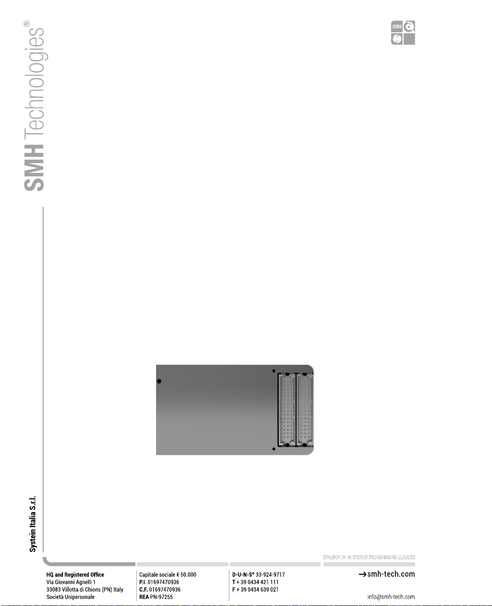
Figure 1: FlashRunner LAN 2.0 Next Generation in closed case version
FlashRunner LAN 2.0 Next Generation comes in one hardware solution, enabling 1
channel for device programming.
Products upgrade for up to 4 active channels are available by asking your sales
reference for a specific upgrade license.
In all of the above configurations, each ISP channel is composed of:
▪Eight digital, bidirectional lines;
▪Two power lines;
▪Ten ground lines (one per digital signal and power line)
10
2.1.1 General features
▪Fastest programming algorithms (as fast as target device’s memory technology
limit), approved by silicon manufacturers;
▪Up to 4 parallel and independent channels
▪Easy ATE integration;
▪Standalone operations
▪Controllable by ATE through optoisolated LAN and USB, or parallel control lines;
▪Supports most ISP protocols (BDM, JTAG, SPI, I2C, MON, ICC, SCI, UART, etc.);
▪Flexible, fully configurable;
▪Compact and robust design for production environments;
▪10Mbyte/sec host data transfer.
2.1.2 Hardware features
▪ISP lines:
◦8 digital I/O lines; 1 ground line per signal;
◦2 programmable output voltages; 1 ground line per power line;
▪1 GBytes on-board RAM memory;
▪On-board timekeeper and calendar for time-stamped log file;
▪LAN Communication Interface
▪Optoisolated USB communication interface.
▪Optoisolated ATE interface for standalone operations
▪Programming voltage measure of each channel
▪Programming current measure of each channel
2.1.3 Software features
▪Linux based operating system;
▪FlashRunner 2.0 WorkBench: the new user-friendly Graphical User Interface
(Windows, Linux and Mac compatible)
▪Controllable by any host system through a terminal utility and simple ASCII
protocol;
▪Up to 32 hardware-selectable projects in Standalone Mode, unlimited software-
selectable projects in Host Mode;
11
▪Interface Library DLL to control the instrument from within user-written
applications;
▪Optional customer binary file cryptography to ensure antipiracy protection
▪Log file and production report file;
▪Erase, blank check, program, read, verify, oscillator trimming, etc.
2.2 Package Checklist
FlashRunner LAN 2.0 Next Generation comes in packaging variants: Open-Frame and
Closed-Case.
The relative packages include the following items:
Table 1: FlashRunner 2.0 NXG Open Frame Package Checklist
Qty.
Description
1
FlashRunner LAN 2.0 Next Generation Open Frame Unit
1
ISP Flat Cable Extension 30cm
1
Ethernet cross cable 2 meter RJ45
1
Micro USB2 cable 1.8 meter
1
Control Interface Flat Cable 15cm
1
Control Interface Board
1
Cable Interface Board
1
DIN41612 Connector 48 pin male IDC
2
Cable Interface Strip connector 10 x 2 h=8mm
1
Control Interface Strip connector 7 x 2 h=8mm
1
3-Year Warranty Sheet
1
FRLAN2P0NXG Pinout Reference
1
FRLAN2P0NXG Quick Start Guide
1
FRLAN2P0NXG Connection Reference Document
1
15V 40W AC/DC Wall Switching Power Adapter
2
M3x6 round head allen key screws

12
Table 2: FlashRunner 2.0 NXG Closed Case Package Checklist
Qty.
Description
1
FlashRunner LAN 2.0 Next Generation Closed Case Unit
1
Control Interface Flat Cable 15cm
1
ISP Flat Cable Extension 30cm
1
Ethernet cross cable 2 meter RJ45
1
Micro USB2 cable 1.8 meter
1
Panel Bracket for FRLAN2P0NXG-CS
1
Control Interface Board
1
Cable Interface Board
1
DIN41612 Connector 48 pin male IDC
2
Cable Interface Strip connector 10 x 2 h=8mm
1
Control Interface Strip connector 7 x 2 h=8mm
1
3-Year Warranty Sheet
1
FRLAN2P0NXG Quick Start Guide
1
FRLAN2P0NXG Pinout Reference
1
15V 40W AC/DC Wall Switching Power Adapter
1
FRLAN2P0NXG Connection Reference Document
2
M3x6 round head hex key screws
2
M3x6 TCEI hex socket screws
When either a 3 or 4 channels version is purchased, the following items will be
included in the package:
Table 3: Package addons for 3/4 channels versions
Qty.
Description
1
Cable Interface Board
1
ISP Flat Cable Extension 30cm
1
DIN41612 Connector 48 pin male IDC
2
Cable Interface Strip connector 10 x 2 h=8mm

13
2.3 Hardware Overview
2.3.1 Power Supply
FlashRunner LAN 2.0 Next Generation is powered through a 15V power supply
connected to a DC plug connector.
2.3.2 ATE Control Connector
ATE Control DIN Connectors are used by an ATE system to control FlashRunner LAN
2.0 Next Generation instead of communicating with the instrument through the USB or
LAN port. You could define and start a project, and check results. For more
information please check chapter 4.3.
Figure 2: Power jack, ATE control connector, USB and LAN
14
2.3.3 LAN Connector
LAN Connector is used to communicate with Host PC system. Use provided cross
cable to connect FlashRunner LAN 2.0 Next Generationwith your PC. For more
information check chapter 2.3.3 and check related documentation on FlashRunner 2.0
Programmer's Manual to correctly set up your host PC system
2.3.4 USB Connector
Alternatively, communication with the host PC can be done with the micro USB
connector. Use the provided USB cable to connect FlashRunner LAN 2.0 Next
Generationwith your PC. For more information check chapter 2.3.4 and check related
documentation on FlashRunner 2.0 Programmer’s Manual to correctly set up your
host PC system
2.3.5 ISP Connectors
In Illustration 3 you can see two ISP connectors, the one on the right will define
channels 1 and 2, the left one will define channels 3 and 4. For more information
check chapter 2.3.5.
Figure 3: “ISP” DIN connectors group

15
2.3.6 LEDs
▪POWER: the instrument is turned on
▪STATUS: indicates system warnings
▪BUSY: turned on when a project is running
▪CHANNEL 1..4: programming result.
Green: programming successful, Red: programming failed
The STATUS_LED indicates whether the Hardware SelfTest, running during the boot
phase that tests all the hardware peripherals connected on the i2c buses, such as
DAC and ADC for the measurement of VPROG currents and voltages has been
successful. If the test passes, the STATUS_LED stays on. If the test fails, the
STATUS_LED blinks. If the STATUS_LED remains off there is something wrong.
Figure 4: FlashRunner LAN 2.0 Next Generation Top Panel

16
2.4 Programming Drivers and Licenses
FlashRunner LAN 2.0 Next Generation includes programming drivers for several
devices. To program a specific device, however, a specific license file for that device,
that family or that silicon producer must be purchased.
i
Note: FlashRunner LAN 2.0 Next Generation comes already preinstalled
with the license(s) you specified at the moment of purchase. You can
purchase additional licenses at any future moment.
Programming drivers and license files are stored inside FlashRunner LAN 2.0 Next
Generation storage memory (see the FlashRunner 2.0 Programmer’s Manual for more
information).
There are several types of licensing:
▪Single device license: only that single device programming is enabled
▪Family license: only a single device family programming is enabled
▪Silicon Producer license: only a single device silicon producer is enabled
2.4.1 Installing New Licenses
When you buy an additional license for a specific device, you will get a license file
(.lic);
If you ordered a new device development, you will also receive:
▪A driver file (.so)
For detailed information on how to update FlashRunner LAN 2.0 Next Generation
please check FlashRunner 2.0 Programmer’s Manual.

17
2.5 Channel Upgrade Licenses
If you would like to upgrade from FR2.0A4 to FR2.0A8, or from FR2.0A12 to
FR2.0A16, you could purchase a Channel Upgrade License. Please ask our Sales
Team (sales@smh-tech.com).
2.6 Upgrading the Firmware
FlashRunner LAN 2.0 Next Generation firmware can be easily upgraded using the
FlashRunner 2.0 WorkBench software. For more information, please refer to the
FlashRunner 2.0 Programmer’s Manual.
18
3 System Setup
3.1 Overview
i
Note: Keep FlashRunner LAN 2.0 Next Generation always in a well-
ventilated area in order to prevent product overheating, which could
affect product performance and, if maintained for a long time, it could
damage product hardware components.
This chapter will explain how to set up FlashRunner LAN 2.0 Next Generation for the
first time. The new FR2.0 WorkBench project Wizard allows an easy and fast system
setup.
When moving FlashRunner LAN 2.0 Next Generation to the production environment,
you can take full advantage of the FR2.0 WorkBench GUI Production Tool (Host
mode) or let the instrument be controlled through the “ATE Control” interface
(Standalone mode).
For more information about Standalone mode and Host mode, see the FlashRunner
2.0 Programmer’s Manual.
3.2 Software Setup
Please refer to the “System Setup/Upgrade” chapter of FlashRunner 2.0
Programmer’s Manual.
3.3 Hardware Setup
To set up FlashRunner LAN 2.0 Next Generation, you must follow the steps below in
the following order:

19
▪Interface FlashRunner LAN 2.0 Next Generation with your test/programming
equipment;
▪Connect FlashRunner LAN 2.0 Next Generation to host PC system (if you use it in
Host Mode);
▪Power up FlashRunner LAN 2.0 Next Generation;
▪Set up LAN settings (if you use the Ethernet connection);
3.3.1 Interfacing with your Test/Programming equipment
Build one or more ISP cables to connect FlashRunner LAN 2.0 Next Generation ISP
connectors to your target board(s). Wire up all the required connections (power,
oscillator, ISP signals) to target microcontrollers using the PinMap tool (for more
details please check the related chapter on FlashRunner 2.0 Programmer’s Manual).
3.3.2 Connecting to the Host PC System
You can connect FlashRunner LAN 2.0 Next Generation to the host system through
either the USB or LAN port.
FlashRunner LAN 2.0 Next Generation comes with a USB cable and an Ethernet
cross cable to connect directly to a host PC.
3.3.3 Powering Up
Power up FlashRunner LAN 2.0 Next Generation by connecting the included power
supply to DC plug connector.
3.3.4 Setting Up LAN Settings
If you connected FlashRunner LAN 2.0 Next Generation to the host PC using the
Ethernet connection, you need to set up the FlashRunner LAN 2.0 Next Generation IP
address. To learn how to set up the FlashRunner LAN 2.0 Next Generation address,
please refer to the FlashRunner 2.0 Programmer’s Manual.
20
4 Connectors
4.1 Overview
FlashRunner LAN 2.0 Next Generation connects to your programming/testing system
through:
▪“ISP” connectors: 48 way, 3 rows, DIN 41612, pitch = 2.54mm (male)
▪“ATE CONTROL” connector: 14 way, 2 rows, pitch = 1.27mm (male)
▪Additionally, a micro USB and Ethernet connectors are provided to interface fully
with the ATE system.
4.2 ISP Connectors
“ISP” connectors group signals needed to program up to 4 target devices. These
connectors are type R/2 DIN41612 (TE part number 5650479-5) with several
input/output lines and power lines.
!
Note: ISP and I/O signals are not optoisolated and are referenced to GND
(power supply ground).
Additionally, in order to avoid undesired current loops between
FlashRunner LAN NXG power supply and target board, a power supply
with a floating output (ground not referenced to the earth potential) should
be used.
This manual suits for next models
2
Table of contents
Other SMH Technologies Motherboard manuals

SMH Technologies
SMH Technologies FlashRunner FR01AT0 User manual

SMH Technologies
SMH Technologies Flashrunner FR01LAN User manual

SMH Technologies
SMH Technologies Flashrunner FR3070A User manual

SMH Technologies
SMH Technologies FlashRunner Cube Series User manual

SMH Technologies
SMH Technologies FlashRunner FR03 User manual

SMH Technologies
SMH Technologies FlashRunner Quattro Series User manual

SMH Technologies
SMH Technologies FlashRunner FR01ENG User manual


