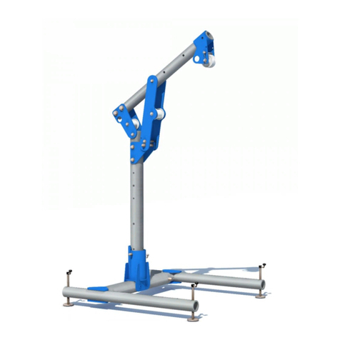
Smiley Lifting Solutions SPYDERCRANE URW094 User manual

OPERATOR’S REFERENCE GUIDE
090-/200-SERIES
Use this Guide with the Following SPYDERCRANE Models:
URW094
URW095
URW095S
URW205
URW205S
URW295
Published by Smiley Liing Soluons, Training Division
May, 2020

2
Forward
This Operator’s Reference Guide for the 090- and 200-Series SPYDERCRANEs is supplementary reference guide for
operang and sustaining your SPYDERCRANE. Smiley Liing Soluons relies on customers like you to comment on
errors and provide advice on how to further develop this guide.
If you have quesons, or concerns, contact SLS Training at:
James@smileyliing.com
(602) 513-0204
Basic Informaon About Your SPYDERCRANE
Idenfy Your SPYDERCRANE 3
Your SPYDERCRANE’s Traveling Specs and Performance 5
Your SPYDERCRANE’s Liing Specs and Performance 6
Your SPYDERCRANE’s Safees and Operator Aids 7
Your SPYDERCRANE’s Remote Controller 9
QuiQ Charger for 110V Baery-Electric Powerplants 10
Maintaining and Servicing Your SPYDERCRANE
The Daily Inspecon 11
Your SPYDERCRANE’s Service Schedule 12
The Lubricaon Points of Your SPYDERCRANE 13
Check/Replace Hydraulic Oil 14
Replace Line Filter 15
Measure/Adjust Crawler Track Tension 16
Replace Crawler Track Drive Oil 17
Check/Replace Motor Oil (Gas) 18
Check/Replace Motor Oil (Diesel) 19
Clean/Replace Air Filter 20
Operang Procedures
Hook and Boom Deployment/Storage Procedure 21
Hook Block Grounding/Un-Grounding Procedure 23
Install the 1-Part Hook Block (Boom) 25
Install the 2-Part Hook Block 26
Install the 4-Part Hook Block 27
Un-Install the 1-Part Hook Block 28
Un-install the 2-Part Hook Block 29
Un-Install the 4-Part Hook Block 30
Store the Wire Rope (Primary Winch) 31
Operang Procedures
Reeve the Wire Rope (Primary Winch) 32
Un-Install the Wire Rope (Primary Winch) 33
Install the Wire Rope (Primary Winch) 34
Install the Jib 35
Ready and Enable the Auxiliary Winch 37
Install the 1-Part Hook (to the Aux. Winch) 37
Store the Wire Rope (Auxiliary Winch) 38
Operang Procedures
Load Charts: URW095 39
Load Charts: URW095S 41
Load Charts: URW205 43
Load Charts: URW205S 45
Load Charts: URW295 47
Load Charts: URW094 49
Working Range Chart: URW094 50
Working Range Chart: URW095S, URW205S 51
Working Range Chart: URW095, URW205, URW295 52
Working Range Chart (Jib): URW095, URW205, URW295 53
Prohibited Zones Chart 54
Troubleshoong
So-Reset the TPD 56
Hard-Reset the TPD 57
CMU Codes (Common and Error) 58

3
Basic informaon about Your SPYDERCRANE
URW094
Ultra-Light Lier
Single Powerplant Opon
110V Baery-Electric
2-Part Hook Block
URW095
Ultra-Light Lier, Expanded Capability
Powerplant Opons:
Gasoline/VPG
Diesel
110V Baery-Electric
220V Electric (as an auxiliary)
2-Part and 1-Part Hook Blocks
Auxiliary Winch Capable
Tilt Jib with Searcher Hook
Reduced Boom Length Opon (URW095S)
URW205
Light/Medium Lier, Expanded Capacity
Powerplant Opons:
Gasoline/VPG
Diesel
110V Baery-Electric
220V Electric (as an auxiliary)
4-Part and 1-Part Hook Blocks
Tilt Jib with Searcher Hook
Auxiliary Winch Capable
URW295
Light/Medium Lier, Expanded Capacity
Powerplant Opons:
Gasoline/VPG
Diesel
110V Baery-Electric
220V Electric (as an auxiliary)
4-Part and 1-Part Hook Blocks
Tilt Jib with Searcher Hook
Auxiliary Winch Capable
How to Find Your SPYDERCRANE’s Model Number and Serial Number
Your SPYDERCRANE’s Model Number and Serial Number are listed on
the Vehicle ID Plate that is installed on the turret.
For the URW094, the Vehicle ID Plate is installed on the turret’s right
side.
For the URWs 095-295, the Vehicle ID Plate is installed on the back of
the turret.

4
Idenfying Your SPYDERCRANE by its Model Number
The rst six digits of your SPYDERCRANE’s model number deter-
mines the overall model. The ve-, six-, or seven-digit sux of the
model number explains the installed powerplants that the SPYDER-
CRANE is equipped with. For example, a URW295 equipped with a gasoline/vapor-propane powerplant is called the URW295CP1URS/P,
while the diesel version of the same SPYDERCRANE is the URW295C4URS.
While the operang characteriscs are largely the same, the powerplant will drive your SPYDERCRANE’s service requirements and
schedule.
This is an example of a full model number; in this case, a Mitsubishi Gas/VPG engine-equipped URW295.
Model Number Descripon
URW094CBURS This the 110V Baery-Electric-equipped URW094. This is the ONLY opon for the URW094.
URW095CP1URS/P
URW205CP1URS/P
URW295CP1URS/P
These are 095-/200-Series SPYDERCRANEs equipped with the Mitsubishi gasoline engine. Vapor-
Propane Gas (VPG) compable.
URW095CP3URS/P
URW205CP3URS/P
URW295CP3URS/P
These are 095-/200-Series SPYDERCRANEs equipped with the Honda gasoline engine. Vapor-Propane
Gas (VPG) compable. There are some addional design dierences between this new model and the
more common CP1, like the Outrigger Grounding Switch and the forward-mounted ignion toggle and
choke.
URW095C4URS
URW205C4URS
URW295C4URS
These are 095-/200-Series SPYDERCRANEs equipped with a diesel engine.
URW095C4UMRS
URW205C4UMRS
URW295C4UMRS
An 095-/200-Series SPYDERCRANE equipped with a diesel engine and a 220V auxiliary powerplant.
URW095CBURS
URW205CBURS
URW295CBURS
An 095-/200-Series SPYDERCRANE equipped the 110V Baery-Electric powerplant.
URW295WBE A very rare URW295 variant equipped with a wheeled chassis and a 220V Baery-Electric powerplant.
Where to Find More Informaon for Your SPYDERCRANE
This guide is helpful for SPYDERCRANE operators who are already trained and qualied and only need refresher knowledge on using the
SPYDERCRANE. If you require more informaon on operang or sustaining your SPYDERCRANE, there are a number of addional resources:
UNIC Operator’s Manual
This manual is very helpful for technical data on the core SPYDERCRANE vehicle (i.e., not the powerpack), but also contains some
basic operator-use informaon. Machine translated from Japanese, UNIC -supplied manuals can be a challenge to read and under-
stand.
UNIC Parts Catalog
The UNIC Parts Catalog contains line drawings and part idencaon informaon for the core SPYDERCRANE (i.e., not the power-
pack, or Jib System). Like the Operator’s Manual, the Parts Catalog is machine translated from Japanese and can be dicult to use.
Other OEM Manuals
Depending on the SPYDERCRANE’s model and installed accessories, you may have addional manuals for the installed powerplant,
or powerplants, or other systems like the Auxiliary Winch.

5
URW094
Tracks
Steel-Core Rubber
5.9 inches x 2.8 inches x 35.4 inches (on-ground) x 2
208.9 square inch contact patch
Weights
and Load-
2,210lbs. (dry)
5.3 PSI Ground Pressure
Engine 48V Baery System with Electric Motor; 7.3 HP @
1,800 RPM
Hydraulic
Pump
3,130 PSI (Traveling) 2990 PSI (Liing)
6.6 gal./minute (4.49 gal. tank capacity)
1800 RPM, Variable-Delivery Piston Pump
Perfor-
mance 1.36 MPH maximum
URW095, URW205, URW295 (Common)
Tracks
Steel-Core Rubber
7.13 inches x 2.9 inches x 41.3 inches (on-ground)
588.7 square inch contact patch
Hydraulic
Pump
3,130 PSI (Traveling) 2990 PSI (Liing)
10 gal./minute (7.13 gal. tank capacity)
2000 RPM (1,800 RPM for 110V), Variable-Delivery
C4URS
Weights
and
4,245lbs. (dry)
7 PSI Ground Pressure
Engine Diesel (JP8/F24 compable);
Perfor- 1.5 MPH maximum
CUBRS
Weights
and
Engine 48V Baery System with Electric
Perfor- 1.3 MPH maximum
CP1URS/P & CP3URS/P
Weights
and
4,100lbs. (dry)
6.96 PSI Ground Pressure
Engine
Gasoline with Vapor Propane
Auxiliary (Mitsubishi & Honda);
13HP @ 2000 RPM
Perfor-
mance 1.4 MPH maximum
Your SPYDERCRANE’s Traveling Specicaons and Performance
Travel/Storage Dimensions
URW094 095-/200-Series

6
Your SPYDERCRANE’s Liing Specicaons and Performance
URW094
Rated Capacity 1,990 lbs. @ 4.9 .
Liing Height 18.3 .
Boom Length 5.6 to 18 .
Max Working Radius 16.9 .
Max Hoist Speed 27.8 ./minute (at 3th layer, with 2-Part
Max Boom Extend 12.3 . in 17seconds
Max Boom Angle Up 12°/second
Max Slew Speed 2.5 RPM
Slew Range 360° connuous
Contact Patch Foot: 3.25” x 4” (13 square inches) x 4
URW095, URW205, URW295
Rated Capacity (095) 1,990 lbs. @ 4.5 . (2-Part Hook Block)
Rated Capacity (205) 5.800 lbs. @ 4.5 . (4-Part Hook Block)
Rated Capacity (295) 6.450 lbs. @ 4.5 . (4-Part Hook Block)
Liing Height 28.9 .
Boom Length 8.3 to 28.4 .
Max Working Radius 27.6 .
Max Hoist (2-Part) 63.2 ./minute (at 4th layer)
Max Hoist (4-Part) 32.8 ./minute (at 4th layer)
Max Boom Extend 20.1 . in 20 seconds
Max Boom Angle Up 7°/second
Max Slew Speed 2.5 RPM
Slew Range 360° connuous
Contact Patch Foot: 4.75” x 5” (23.75 square inches) x 4
URW094 095-/200-Series
MAX-EXT
NOT-MAX
Deployment Footprint Dimensions

7
Your SPYDERCRANE’s Safees and Operator Aids
Safees
System Descripon
Holding Valves
Each hydraulic cylinder used by the SPYDERCRANE (Extend Cylinders for boom telescoping and outrigger deploy-
ment and the Li Cylinder used to change the angle of the boom) is equipped with a holding valve.
The holding valve prevents the cylinder from collapsing if the engine and/or hydraulic pump are shut down. Essen-
ally, if power or hydraulic pressure is lost, the SPYDERCRANE will “lock up” unl pressure is restored.
Addionally, if the hydraulic oil line to a specic cylinder is cut, or bursts, the associated holding valve will lock up
ONLY the aected cylinder; allowing the others to funcon normally.
Locking Pawl The winch of the SPYDERCRANE is equipped with a locking pawl that lowers and prevents the winch from rotang if
hydraulic pressure is lost.
An-Two Block
Safety
The An-Two Block (A2B) Safety is designed to prevent the hook block from being WINCHED UP (or otherwise
raised) into the boom p. Allowing the hook block to smash into the boom p (“two-blocking”) can result in crical
damage to the wire rope, SPYDERCRANE, or the aached load. The A2B Safety prevents this by commanding a CMU
CODE 15 Funcon Kick-Out (FKO) when it is ACTIVATED.
The A2B Safety is acvated when:
The A2B Switch is OPENED by the hook block being WINCHED UP to the point where it impacts and lis the
A2B Weight, which causes the A2B Switch to spring into the OPEN posion. This can also be caused if the
boom is extended WITHOUT WINCHING DOWN the hook (to prevent the hook from rising).
The A2B Switch, or the electrical connecon to it, is broken.
Minimum Wire
Rope Safety
The Minimum Wire Rope Safety is designed to lockout the WINCH DOWN command when acvated (CMU CODE
96). Its purpose is to prevent the operator from WINCHING DOWN unl all of the wire rope is unspooled o the
Wire Rope Drum.
Boom Stored
Safety
The Boom Stored Safety is a limit switch that locks out the SLEW command when acvated. The Boom Stored Safe-
ty is used when storing the hook and boom. The URW094 IS NOT equipped with the Boom Stored Safety.
Safety Latch Every hook block on the SPYDERCRANE is equipped with a spring-loaded safety latch that acts as a one-way gate.
When a load is properly rigged and aached, the Safety Latch keeps the rigging from slipping o the hook.
Operator Aids
System Descripon
Turnover Prevenon Device
The Turnover Prevenon Device (TPD) is a system of load cells and a centralized computer (the TPD
Amplier) that monitors the stability of the SPYDERCRANE and can acvate a CMU CODE 15 FKO
when it detects that the SPYDERCRANE is nearing its stability limits (do to overloading, or boom
movement). The URW094 IS NOT equipped with the TPD.
Boom Angle Indicator
A mechanical operator aid, the Boom Angle Indicator indicates the boom angle of the SPYDER-
CRANE’s boom and can be used in conjuncon with visually determining the Boom Stage to calculate
the SPYDERCRANE’s Working Radius.
Load Chart The Load Chart displays the various Rated Load Capacies for the SPYDERCRANE, based on its Boom
Stage, Working Radius, and Deployment State.
Working Range Chart The Working Range Chart indicates the approximate posion and length of the boom based on its
Working Radius, Boom Angle, and Boom Stage.

8
Your SPYDERCRANE’s Safees and Operator Aids
Visual Warning Systems
System Descripon
Outrigger Mode Indicator The Outrigger Mode Indicator is the yellow lamp located on the top of the Operator Staon and it lights up
when the SPYDERCRANE is placed into Outrigger Mode.
Remote Control Indicator The Remote Control Indicator is the orange lamp located on the top of the Operator Staon and it lights up
when the SPYDERCRANE is placed into Remote Control.
Run Indicator
The Run Indicator is the green tower lamp that strobes whenever the SPYDERCRANE is running. The Run
Indicator is only installed on 095-/200-Series SPYDERCRANEs equipped with the 110V Baery-Electric
powerpack.
Radio Remote Receiver
Status Panel
Located on outward facing panel of the Radio Remote Receiver (bolted to the rear of the Hydraulic Oil
Tank), the Status Panel is a series of red and green LEDs that can be used to troubleshoot problems with
the SPYDERCRANE’s Radio Remote Receiver.
TPD Amplier Status Pan-
el
Located on the outward facing panel of the TPD Amplier (located inside the Operator Staon and viewa-
ble through a sheet metal cutout), the Status Panel is a series of orange, green and red LEDs that can be
used to troubleshoot problems with the Turnover Protecon Device (TPD). The TPD is only installed on 095
-/200-Series SPYDERCRANEs.
Unlike the audible alarms and warning systems, the visual warning indicators and lamps CANNOT be turned o.
Audible Alarms and Warning Systems
System Descripon
Safety Horn
The Safety Horn is used to warn bystanders and can be acvated from:
The Safety Horn Buon in the Travel Control Group (next to the Ignion Switch).
The Safety Horn Buon in the Outrigger Control Group (next to the Crane/ Outrigger Mode Toggle).
The Remote Safety Horn Buon on the Remote Controller.
Voice Mute Switch
The voice mute switch, when set to the OFF posion turns o the audible signals from the voice warning sys-
tems and audible alerts system.
The voice mute switch does not aect audible signals from the LMI, the TPD, or the outrigger mode alarm.
Outrigger Buzzer
Mute Switch This is a mute switch specically for the outrigger mode alarm.
TPD Alarm Mute The TPD alarm mute is an on/o toggle used to mute the alarms associated with the turnover protecon device
(TPD).
While all of the audible alarms and indicators can be switched o, doing so WILL reduce your situaonal awareness. Audible alarms and
indicators should ONLY be turned o when the SPYDERCRANE is being operated where noise controls are in eect.

9
Your SPYDERCRANE’s Remote Controller
Remote Controller Map
#Switch Funcon
1Remote E-Stop
When ACTIVATED, turns OFF the remote controller.
The remote controller CANNOT be turned ON unl the remote e-stop is deacvated (by ro-
tang the e-stop switch clockwise).
2Power Key/Switch 2-posion switch; turns the Remote Controller ON and OFF.
3Remote Mode Buon
This buon will acvate the secondary command modes for the SPYDERCRANE.
The remote mode buon must be held down when selecng command funcons.
For SPYDERCRANEs running on their ICE, holding the remote mode buon and commanding a
BOOM SLEW CLOCKWISE will turn the engine OFF, holding the remote mode buon and com-
manding a BOOM SLEW COUNTERCLOCKWISE will re-start the engine.
4Speed Control Buon
When pressed, places the SPYDERCRANE into one of three SPEED MODES:
RED (default): Up to 100% engine power can be commanded
Yellow: Up to 50% engine power can be commanded
Green: Up to 10% engine power can be commanded
Only used with SPYDERCRANEs running propane, gasoline, or diesel.
5Remote Store Hook Buon When PRESSED AND HELD; commands a HOOK STORE; Control Trigger must also be squeezed
to actuate the command.
6Remote Safety Horn (Start) Repeatedly PRESS to LINK the Remote Controller with the SPYDERCRANE; also sounds the
SPYDERCRANE’s horn.
7Remote Telescope Control Switch PRESS UP to command BOOM OUT; PRESS DOWN to command BOOM IN.
8Remote Winch Control Switch PRESS UP to command WINCH UP; PRESS DOWN to command WINCH DOWN.
9Remote Slew Control Switch PRESS UP to command SLEW LEFT; PRESS DOWN to command SLEW RIGHT.
10 Remote Boom Angle Control
Switch PRESS UP to command BOOM UP; BOOM DOWN to command BOOM DOWN.
11 Remote Control Trigger Squeeze to apply hydraulic funcon to selected command.

10
QuiQ Charger for 110V Baery-Electric Powerplants
The locaon of the QuiQ Charger varies by
SPYDERCRANE:
On the URW094, the QuiQ Charger is in-
stalled in the open on the roadside of the
carrier, on the opposite side of the Hydraulic
Oil Tank.
On the ICE- and 110V Baery-equipped 095-
and 200-series SPYDERCRANEs, the QuiQ
Charger is tucked in behind the carrier cab
sheet metal on the roadside.
QuiQ Charger Status Panel
AMMETER LAMPS (Bulk Charge State)
Displays approximate baery charge level during the bulk charging phase (up to
60%).
If FLASHING, the baery array is overheang and NOT CHARGING.
ABSORPTION PHASE INDICATOR
If SOLID YELLOW, baeries are at 80% (Bulk Phase Complete)
If FLASHING YELLOW, baeries are disconnected
CHARGE COMPLETION INDICATOR
If SOLID GREEN, baeries are charged, charger is in Maintenance Phase
If FLASHING GREEN, the absorpon charge phase is ended, and the nishing
phase is in process.
AC INDICATOR
If SOLID AMBER, AC Power input is good
If FLASHING AMBER, AC Power Voltage is LOW, check voltage at power point
and/or extension cord
FAULT INDICATOR
If FLASHING RED, Quiq Charger has an internal error; aempt re-boot.
If ashing returns, check the ash code for maintenance support:
Single ash (ash-o-ash…):
This indicates that there is a problem with the connecon between
the charger and the baery OR the baery array is out of its safe
operang temperature range (14- to 122-degrees, Fahrenheit).
Double ash (ash-ash-o-ash-ash-o…):
This indicates that detected baery voltage is out-of-range (less
than 36V, or more than 55.2V).
Triple ash:
This indicates a charging meout, either because the baery array
is NOT reaching the required voltage OR the baery charger is
overheang. This could be due to a bad connecon to the baery
array.
Four ashes:
This indicates that the baery array cannot be charged to mini-
mum voltage. This is could be due to a damaged baery cell.

Five ashes:
This indicates that charging has stopped due to overheang within
the 110V baery system. This could be due to insucient airow
around the SPYDERCRANE.
Six ashes:
A baery charger internal fault, aempt unplugging for more than
15 seconds and plugging back in.

11
Component Check For: Sat. Unsat. N/A
Carrier Rear
Storage Compartment Conrm contents and inspect the compartment for damage/corrosion
Travel Control Group Damage to individual controls
1-Part Hook and Holder Security, corrosion, and damage; check Safety Latch
Hydraulics/Electrical Leaks, worn/damaged wiring at turret rear
Start-Up Start the SPYDERCRANE, conrm normal start-up
Crane Mode Transion SPYDERCRANE to Crane Mode, conrm normal switch-over
Carrier Roadside
Outrigger #3 Structural damage, hydraulic leaks
Le-Side Turret Structural damage, hydraulic leaks
Roadside Track Drive Damage, loose track, hydraulic leaks
Jib System Structural damage, missing components
Outrigger #4 Structural damage, hydraulic leaks
Li Cylinder Check for structural damage, hydraulic leaks
Winch Check for structural damage, proper wire rope lay
Carrier Cab
Outrigger Mode Transion SPYDERCRANE to Outrigger Mode, conrm normal switch-over,
conrm Outrigger Mode Indicator lights up
Outrigger Control Group Check controls, including Outrigger Mode Indicator
Alarm Switch Posion Ensure all alerts are set to ON, conrm TPD Lockout Alarm, Outrigger Mode
Alarm, and Voice Warning System acve
Engine Hours Record engine run hours
Remote Control Transion SPYDERCRANE to Remote Control, conrm normal switch-over,
conrm Remote Control Indicator lights up
A2B Switch/Extension Inspect A2B Switch, Lanyard, and Weight for damage/corrosion
Wire Rope Socket Inspect installed 4-Part Hook Block Wire Rope Socket and/or any Wire Rope
Sockets for installed Hook Blocks
4-Part/2-Part Hook Damage, corrosion, Safety Latch funcon
Boom Tip Damage, corrosion
Cab Check for overall damage to carrier cab sheet metal and installed decals
Carrier Curbside
Outrigger #1 Structural damage, hydraulic leaks
Hydraulic Oil Tank Structural damage, hydraulic leaks
Right-Side Turret Structural damage, hydraulic leaks
Curbside Track Drive Damage, loose tracks, hydraulic leaks
Outrigger #2 Structural damage, hydraulic leaks
Daily Inspecon

12
Service Schedule by MODEL and POWERPLANT
094-Series
Service Descripon Interval
Product
Check/Replace Hy-
draulic Oil
The URW094 carries 4.5 gallons of hydraulic oil in
its tank. Use the sight glass to check the level and
replace, as needed.
3 months (rst me)
Every 500 hours of operaon thereaer
Shell Tellus 32
NSN:9150-01-336-6589
Replace Track Drive
Wheel Oil
Drain and replace the oil within the two Crawler
Track Drive Wheels. Every 1000 hours
Gear Oil 75W90
NSN: 9150-01-035-5390
Replace Line Filter Replace the in-line hydraulic oil lter. Aer 1 year of operaon
Aer replacement of pump
P/N: 7405 80036
110V Baery/Electric and 220V Electric (CBURS, CMURS)
Service Descripon Interval
The 110V Baery/Electric and 220V Electric SPYDERCRANEs use sealed powerpacks and do not require engine/motor maintenance.
095- and 200-Series
Service Descripon Interval
Product
Check/Replace Hy-
draulic Oil
The URW0095 and URW2XX carries 7 gallons of
hydraulic oil in its tank. Use the sight glass to check
the level and replace, as needed.
3 months (rst me)
Every 500 hours of operaon thereaer
Shell Tellus 32
NSN:9150-01-336-6589
Replace Track Drive
Wheel Oil
Drain and replace the oil within the two Crawler
Track Drive Wheels. Every 1000 hours
Gear Oil 75W90
NSN: 9150-01-035-5390
Replace Line Filter Replace the in-line hydraulic oil lter. Aer 1 year of operaon
Aer replacement of pump
P/N: 7405 80036
Gasoline (CP1URS and CP3URS)
Service Product Descripon Interval
Clean Air Filter PN: UW6703170 Remove, wash, dry, and install the Air Filter. 3 months (rst me)
Every 500 hours of operaon thereaer
Replace Motor Oil 10W40 Drain and replace the motor oil in the gasoline en-
gine (1.3 quarts). Every 50 engine hours
Diesel (C4URS)
Service Product Descripon Interval
Replace Air Filter Replace Air Filter. Every 250 engine hours
Replace Motor Oil and
Filter 15W40 Drain and replace the motor oil in the gasoline en-
gine (2.65 quarts).
First 50 engine hours
Every 250 engine hours thereaer

13
Lubricaon Points of Your SPYDERCRANE
094-Series Lubricaon
#Component Lubricant Applicaon
1Boom Secons Molybdenum Grease (NLGI 1,2) Manually apply to exposed boom
2Boom Hinge Pin Grease Fing Molybdenum Grease (NLGI 1,2) Grease Gun
3Li Cylinder Grease Fing (Upper) Molybdenum Grease (NLGI 1,2) Grease Gun
4Li Cylinder Grease Fing (Lower) Molybdenum Grease (NLGI 1,2) Grease Gun
5Slew Gear Grease Fing Molybdenum Grease (NLGI 1,2) Grease Gun
6Outrigger Deployment Pivot (x4) Molybdenum Grease (NLGI 1,2) Grease Gun
XWire Rope Wire Rope Lubricant Aerosol Spray
095-/200-Series Lubricaon
#Component Lubricant Applicaon
1Boom Secons Molybdenum Grease (NLGI 1,2) Manually apply to exposed boom
2Boom Hinge Pin Grease Fing Molybdenum Grease (NLGI 1,2) Grease Gun
3Li Cylinder Grease Fing (Upper) Molybdenum Grease (NLGI 1,2) Grease Gun
4Li Cylinder Grease Fing (Lower) Molybdenum Grease (NLGI 1,2) Grease Gun
5Slew Gear Grease Fings (x2) Molybdenum Grease (NLGI 1,2) Grease Gun
6Outrigger Deployment Pivot (x8) Molybdenum Grease (NLGI 1,2) Grease Gun
7Boom Secon One Grease Fings (x2) Molybdenum Grease (NLGI 1,2) Grease Gun
8Winch Gear Grease Fing Molybdenum Grease (NLGI 1,2) Grease Gun
XWire Rope Wire Rope Lubricant Aerosol Spray

14
Check/Replace the Hydraulic Oil
Vehicle Start Condion
090-/200-Series
Travel Mode
Hook Block (any) Installed
OFF
Personnel and Time Needed
1 Person
Standard PPE
<5 minutes
Tools and Equipment Needed
Hydraulic Oil (4.5 gal for 094 and 7.14 gal
for 095- and 200-Series)
WARNING: You MUST leave the SPYDERCRANE OFF and allow enough me for the all of the onboard uids (including the hydraulic oil)
to return to ambient temperature before performing ANY maintenance.
NOTE: When checking or lling the Hydraulic Oil Tank, the SPYDERCRANE MUST be in Travel Mode with the outriggers and boom in their
stored condions.
1. Unlock and rotate (but do not pre-deploy) Outriggers #1 and #2 to expose the Hydraulic Oil Tank; check the oil level using the aached
Sight Glass (Fig. 1 and 2).
2. To add oil, unscrew and remove the Hydraulic Oil Tank Cap and add oil unl the Sight Glass reads a full tank.
3. Replace Hydraulic Oil Tank Cap.
(Fig. 1): The 4.5 gal Hydraulic Oil Tank for URW094, the Sight Glass has been highlighted. (Fig. 2): The 7.14 gal Hydraulic Oil Tank for 095- and 200-Series SPYDERCRANEs, the Sight Glass
has been highlighted.

15
Replace the Hydraulic Line Filter
Vehicle Start Condion
090-/200-Series
Travel Mode
Hook Block (any) Installed
OFF
Personnel and Time Needed
1 Person
Standard PPE
<5 minutes
Tools and Equipment Needed
New Hydraulic Line Filter
10mm
32mm
WARNING: You MUST leave the SPYDERCRANE OFF and allow enough me for the all of the onboard uids (including the hydraulic oil)
to return to ambient temperature before performing ANY maintenance.
1. Remove the Line Filter Access Cover bolts (10mm).
2. Unscrew the Line Filter , rst at the output side, then the input side (Fig. 1 and 2).
3. Aer removing the Line Filter from the input side of the hydraulic oil line, prop the hydraulic oil line to keep oil in the line from spilling.
4. Install the new Line Filter and replace the access cover.
(Fig. 1): The Hydraulic In-Line Filter for the URW094, the lter is aached to the boom of the
Hydraulic Control Valve, behind an access panel.
(Fig. 2): The Hydraulic In-Line Filter for the 095- and 200-Series, the lter is aached to the
boom of the Hydraulic Control Valve, behind an access panel.

16
Check/Adjust Crawler Track Tension
Vehicle Start Condion
090-/200-Series
Travel Mode
OFF
Personnel and Time Needed
1 Person
Standard PPE
<5 minutes
Tools and Equipment Needed
Metric Ruler, or 10mm and 15mm gauge
32mm open-end box wrench
1. With the SPYDERCRANE OFF and resng on its tracks, measure the distance between the inside crawler track teeth and the top of the
Roller Truck (Fig. 1).
• If the crawler tracks are properly tensioned, the gap between the boom of the teeth and the top of the Truck Roller should
be between 15mm to 17mm.
• If the gap is 10mm, or less, they MUST BE tensioned.
2. To tension the crawler tracks, rst nd the Crawler Track Tensioner Access Port on Roller Truck, then insert a 32mm open-end box
wrench to loosen the Jam Nut (the nut nearest the Drive Wheel) and then turn the Tension Nut (the nut nearest the Idler Wheel) unl
the tracks are properly tensioned (Fig. 2).
• Turning the Tension Nut CCW will TIGHTEN the tracks, CW will LOOSEN the tracks.
3. When the Crawler Track has been properly tensioned, ghten the Jam Nut to secure the Tension Nut.
(Fig. 1): Measure the gap between the crawler track teeth and the top of the Roller Truck as
close to the middle of the Roller Truck as possible.
(Fig. 2): The Jam Nut (blue) is nearest the Drive Wheel, the Tension Nut (ref) in nearest the
Idler Wheel.

17
Replace Crawler Track Drive Wheel Oil
Vehicle Start Condion
090-/200-Series
Deployed
Hook and Boom STORED
Personnel and Time Needed
1 Person
Standard PPE
<5 minutes
Tools and Equipment Needed
Hydraulic Oil
8mm Allen Wrench
PFTE Tape
1. Place the SPYDERCRANE into Travel Mode (while it is sll deployed on its outriggers) and turn the Drive Wheels unl they are oriented
so that the Drain Port is at the 6 o’clock posion (Fig. 1).
WARNING: You MUST leave the SPYDERCRANE OFF and allow enough me for the all of the onboard uids (including the hydraulic oil to
return to ambient temperature before performing ANY maintenance.
2. Remove the Fill Port Plug to bleed any air in the Drive Wheel (8mm).
3. Remove the Drain Port Plug to drain oil out of the Drive Wheel (8mm), inspect the O-ring of the plug, replace the PFTE tape on the
threads, and replace the plug.
4. Add oil through the Fill Port unl the Drive Wheel is lled (Fig. 2).
5. Inspect the O-ring of the Fill Port Plug, replace the PFTE on the threads, and replace the plug.
(Fig. 1): The larger Drain Port should be at the 6 o’clock posion before it’s plug is removed.
(Fig. 2): Aer replacing the Drain Port Plug, add oil through the Fill Port unl the Drive Wheel is
lled.

18
Check/Replace Motor Oil (Gas Engine)
Vehicle Start Condion
095-/200-Series
(CP1, CP3)
Travel Mode
OFF
Personnel and Time Needed
1 Person
Standard PPE
<15 minutes
Tools and Equipment Needed
Motor Oil (1.3 quarts)
WARNING: You MUST leave the SPYDERCRANE OFF and allow enough me for the all of the onboard uids to return to ambient temper-
ature before performing ANY maintenance.
Check the Motor Oil
1. Run the engine of the SPYDERCRANE for 2 minutes, shut it down, and wait another 5 minutes before checking the motor oil level.
2. Remove the dip sck, from the Fill Port clean it with a rag and insert back into the ll port (but, DO NOT screw it in)(Fig.1).
3. Remove the dip sck and check the oil level, using the gauge on the sck (Fig. 1).
Replace the Motor Oil
1. Remove the Drain Plug and drain all of the oil in the engine (Fig. 2).
2. Replace the Drain plug, and add oil through the Fill Port.
(Fig. 1): Aer cleaning the dip sck, re-insert it into the engine and remove to check the engine
oil.
(Fig. 2): Drain the Engine Oil by removing the Drain Plug.

19
Check/Replace Motor Oil and Filter (Diesel Engine)
Vehicle Start Condion
095-/200-Series
(C4)
Travel Mode
OFF
Personnel and Time Needed
1 Person
Standard PPE
<15 minutes
Tools and Equipment Needed
Motor Oil (2.65 quarts)
Oil Filter
WARNING: You MUST leave the SPYDERCRANE OFF and allow enough me for the all of the onboard uids to return to ambient temper-
ature before performing ANY maintenance.
Check the Motor Oil
1. Run the engine of the SPYDERCRANE for 2 minutes, shut it down, and wait another 5 minutes before checking the motor oil level.
2. Remove the dip sck, from the Fill Port clean it with a rag and insert back into the ll port (but, DO NOT screw it in) (Fig. 1).
3. Remove the dip sck and check the oil level, using the gauge on the sck.
Replace the Motor Oil
1. Remove the Drain Plug and drain all of the oil in the engine.
2. Replace the Oil Filter, making sure to lubricate the O-ring of the new lter with a thin layer of oil before spinning it onto the engine.
3. Replace Drain Plug, add oil through Fill Port, and replace and secure dip sck (Fig.2).
(Fig. 1): Aer cleaning the dip sck, re-insert it into the engine and remove to check the engine
oil.
(Fig. 2): Aer draining the engine oil, replace the Oil Filter.

20
Clean/Replace Air Filter
Vehicle Start Condion
095-/200-Series
(CP1, CP3, C4)
Travel Mode
OFF
Personnel and Time Needed
1 Person
Standard PPE
<15 minutes
Tools and Equipment Needed
Air Filter (Diesel)
WARNING: You MUST leave the SPYDERCRANE OFF and allow enough me for the all of the onboard uids to return to ambient temper-
ature before performing ANY maintenance.
Clean and Install Air Filter (Gasoline Engine)
1. Access the Air Filter Housing through the access panel on the front of the SPYDERCRANE Carrier Cab.
2. Un-clamp and remove the Air Filter Housing and remove the Air Filter (Fig. 1).
3. Wash the Air Filter with clean water and allow to completely dry.
4. Install the Air Filter and clamp the Air Filter Housing Cover closed (Fig. 1).
Remove and Replace the Air Filter (Diesel Engine)
1. Access the Air Filter Housing through the access panel on the front of the SPYDERCRANE Carrier Cab.
2. Remove the Air Filter Bolt and pull the enre Air Filter element out of the housing (Fig. 2).
3. Insert new Air Filter element and replace Air Filter Bolt (Fig. 2).
(Fig. 1): Aer cleaning the dip sck, re-insert it into the engine and remove to check the engine
oil.
(Fig. 2): Drain the Engine Oil by removing the Drain Plug.
This manual suits for next models
5
Table of contents
Other Smiley Lifting Solutions Lifting System manuals
Popular Lifting System manuals by other brands

MW TOOLS
MW TOOLS HB240 manual

Savaria
Savaria K2 owner's manual

Challenger Lifts
Challenger Lifts CL4P9S Installation, operation & maintenance manual

TRANZSPORTER
TRANZSPORTER TP250 owner's manual

Hi-Force
Hi-Force HPS Series Operating instructions manual

BorMann
BorMann BWR5119 Assembly and operation instructions